Snell & Wilcox HD2300 Administrator Guide

HD23INOPS 060704 www.snellwilcox.com Version 1 Issue 1 0.1
HD2300
Broadcast Downconverter
Installation & Operator’s
Manual
© July 2004
www.snellwilcox.com
Snell & Wilcox Ltd., Southleigh Park House, Eastleigh Road, Havant, Hants, PO9 2PE, United Kingdom.
For technical assistance contact: Tel: +44 (0)23 9248 9000 Fax: +44 (0)23 9245 1411
For general and sales assistance contact: Tel: +44 (0)20 8917 4300 Fax: +44 (0)20 8607 9466

HD2300 SECTION 0
HD23INOPS 060704 www.snellwilcox.com Version 1 Issue 1 0.2
Explanation of Safety Symbols
This symbol refers the user to important information contained in
the accompanying literature. Refer to manual.
This symbol indicates that hazardous voltages are present inside.
No user serviceable parts inside.
This unit should only be serviced by trained personnel.
Servicing instructions where given, are for use by
qualified service personnel only.
To reduce risk of electric shock do not perform any
servicing other than that contained in the operating
instructions unless you are qualified to do so.
Refer all servicing to qualified personnel.
To reduce the risk of electric shock, do not expose this appliance
to rain or moisture.
Always ensure that the unit is properly earthed and power connections
correctly made.
This equipment must be supplied from a power system providing a
PROTECTIVE EARTH connection and having a neutral connection
which can be reliably identified.
The power outlet supplying power to the unit should be close to the
unit and easily accessible
Power connection in countries other than the USA
The equipment is normally shipped with a power cable with a standard IEC
moulded free socket on one end and a standard IEC moulded plug on the other.
If you are required to remove the moulded mains supply plug, dispose of the
plug immediately in a safe manner.
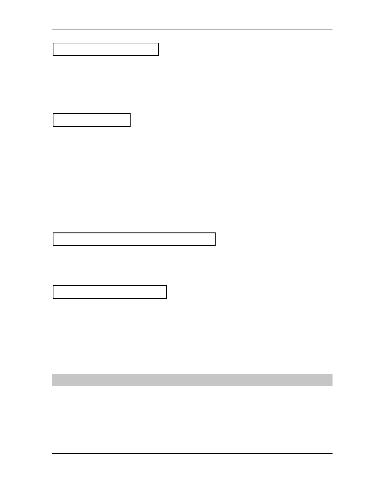
The colour code for the lead is as follows:
GREEN/YELLOW lead connected to E
(Protective Earth Conductor)
BLUE lead connected to N (Neutral Conductor)
BROWN lead connected to L (Live Conductor)
Caution If the unit has two mains supply inputs ensure that both power
cords are plugged into mains outlets operating from the same phase.
LN
E
NL
E
GB
!
CAUTION
RISK OF ELECTRIC SHOCK
DO NOT REMOVE COVERS
NO USER SERVICEABLE PARTS
REFER SERVICING TO QUALIFIED
PERSONNEL ONLY
!
!
Safety Warnings
Légende :
Ce symbole indique qu'il faut prêter attention et se référer
au manuel.
Ce symbole indique qu'il peut y avoir des tensions électriques
à l'intérieur de l'appareil. Ne pas intervenir sans l'agrément
du service qualifié.
Pour réduire le risque de choc électrique, ne pas exposer l'appareil
dans un milieu humide.
Toujours s'assurer que l'unité est correctement alimentée,
en particuliers à la liaison à la terre.
La source électrique de cet équipement doit posséder une connexion
à la terre , ainsi qu'une liaison « neutre » identifiable.
La prise électrique qui alimente l'appareil doit être proche
de celle-ci et accessible.
Câble secteur de pays autres que les Etats-Unis
L'équipement est livré avec un câble secteur au standard IEC, moulé
mâle/femelle.
Si vous souhaitez changr la prise mâle de votre cordon, voici les
codes couleurs des fils :
Le fil VERT/JAUNE est connecté à T (Terre)
Le fil BLEU est connecté à N (Neutre)
Le fil MARRON est connecté à P (Phase)
Attention si l'appareil a 2 alimentations, s'assurer que les cordons
soient branchés sur la même phase.
Précaution d'emploi :
F
Les procédures de maintenance ne concernent
que le service agréé. Afin de réduire le risque de
choc électrique, il est recommandé de se limiter
aux procédures d'utilisation, à moins d'en être qualifié.
Pour toute maintenance, contacter le service compétent.
!
ATTENTION
RISQUE DE CHOC ELECTRIQUE
NE PAS RETIRER LE COUVERCLE
NE PAS INTERVENIR SANS
L'AGREMENT DU SERVICE
QUALIFIE
PN
T
NP
T
Connecteur Prise
!
!
Erklärung der Sicherheitssymbole
Dieses Symbol weist den Benutzer auf wichtige Informationen
hin, die in der begleitenden Dokumentation enthalten sind.
Dieses Symbol zeigt an, dass gefährliche Spannung vorhanden ist.
Es befinden sich keine vom Benutzer zu wartenden Teile im Geräteinneren.
Dieses Gerät sollte nur von geschultem Personal gewartet werden
Um das Risiko eines Elektroschocks zu reduzieren, setzen Sie das
Gerät weder Regen noch Feuchtigkeit aus.
Stellen Sie immer sicher, dass das Gerät ordnungsgemäß geerdet
und verkabelt ist.
Dieses Equipment muss an eine Netzsteckdose mit Schutzleiter
angeschlossen werden und einen zuverlässig identifizierbaren Nullleiter haben.
Die Netzsteckdose sollte nahe beim Gerät und einfach zugänglich sein.
Netzanschluss in anderen Ländern als der USA
Das Equipment wird im Normalfall mit einem Netzkabel mit Standard IEC
Anschlussbuchse und einem Standard IEC Anschlussstecker geliefert.
Sollten Sie den angeschweißten Stecker auswechseln müssen, entsorgen
Sie diesen bitte umgehend. Die farbliche Belegung des Netzkabels ist wie folgt:
GRÜN GELB E = Schutzleiter
BLAU N = Nulleiter
BRAUN L = P = Phase
Achtung: Wenn das Gerät zwei Anschlussbuchsen hat, stellen
Sie bitte sicher, dass beide Netzkabel mit der selben Phase in die
Netzsteckdose gesteckt werden.
Sicherheits-Warnhinweise
D
!
!
Die angeführten Service-/Reparatur-Anweisungen sind
ausschließlich von qualifiziertem Service-Personal
auszuführen. Um das Risiko eines lektroschocks zu
reduzieren, führen Sie ausschließlich die im
Benutzerhandbuch eschriebenen Anweisungen aus,
es sei denn, Sie haben die entsprechende Qualifikation.
Wenden Sie sich in allen Service-Fragen an qualifiziertes Personal.
!
ACHTUNG
Gefahr von Elektroschocks.
Abdeckungen nicht entfernen
Keine vom Benutzer zu wartende Teile
Wenden Sie sich ausschließlich
an qualifiziertes Personal
L=
Phase
N=
Nulleiter
N=
Nulleiter
L=
Phase
E=
Schutzleiter
E=
Schutzleiter
Explicación de los Símbolos de Seguridad
Éste símbolo refiere al usuario información importante contenida
en la literatura incluida. Referirse al manual.
Éste símbolo indica que voltajes peligrosos están presentes en el interior.
No hay elementos accesibles al usuario dentro.
Esta unidad sólo debería ser tratada por personal cualificado.
Las instrucciones de servicio cuando sean dadas, son
sólo para uso de personal cualificado. Para reducir el
riesgo de choque eléctrico no llevar a cabo ninguna
operación de servicio aparte de las contenidas en las
instrucciones de operación, a menos que se esté
cualificado para realizarlas.
Referir todo el trabajo de servicio a personal cualificado.
Para reducir el riesgo de choque eléctrico, no exponer este equipo
a la lluvia o humedad.
Siempre asegurarse de que la unidad está propiamente conectada a
tierra y que las conexiones de alimentación están hechas correctamente.
Este equipo debe ser alimentado desde un sistema de alimentación
con conexión a TIERRA y teniendo una conexión neutra fácilmente
identificable.
La toma de alimentación para la unidad debe ser cercana y fácilmente
accesible.
Conexión de alimentación en otros países que no sean USA
El equipo es normalmente entregado con un cable de alimentación con un
enchufe hembra estándar IEC en un extremo y con una clavija estándar
IEC en el otro. Si se requiere eliminar la clavija para sustituirla por otra,
disponer dicha clavija de una forma segura.
El código de color a emplear es como sigue:
Advertencia Si la unidad tuviera dos tomas de alimentación, asegurarse
de que ambos cables de alimentación están conectados a la misma fase.
ESP
!
!
Advertencias de Seguridad
LN
E
NL
E
Clavija
Aerea Macho Enchufe
Aereo Hembra
VERDE/ AMARILLO conectado a E
(Conductor de protección a Tierra
-Earth en el original-)
AZUL conectado a N (Conductor Neutro -Neutral en el original-)
MARRÓN conectado a L (Conductor Fase -Live en el original-)
RIESGO DE CHOQUE ELECTRICO
NO QUITAR LAS PROTECCIONNES
ELEMENTOS NO ACCESIBLES AL
USUARIO.
SERVICIO SOLAMENTE A PERSONAL
CUALIFICADO

HD2300 SECTION 0
HD23INOPS 060704 www.snellwilcox.com Version 1 Issue 1 0.3
Simboli di sicurezza:
Questo simbolo indica l'informazione importante contenuta nei
manuali appartenenti all'apparecchiatura. Consultare il manuale.
Questo simbolo indica che all'interno dell'apparato sono presenti
tensioni pericolose. Non cercare di smontare l'unità.
Per qualsiasi tipo di intervento rivolgersi al personale qualificato.
Le istruzioni relative alla manutenzione sono ad uso
esclusivo del personale qualificato. E' proibito all'utente
eseguire qualsiasi operazione non esplicitamente
consentita nelle istruzioni. Per qualsiasi informazione
rivolgersi al personale qualificato.
Per prevenire il pericolo di scosse elettriche è necessario non esporre
mai l'apparecchiatura alla pioggia o a qualsiasi tipo di umidità.
Assicurarsi sempre, che l'unità sia propriamente messa a terra e che
le connessioni elettriche siano eseguite correttamente.
Questo dispositivo deve essere collegato ad un impianto elettrico
dotato di un sistema di messa a terra efficace.
La presa di corrente deve essere vicina all'apparecchio
e facilmente accessibile.
Connessione elettrica nei paesi diversi dagli Stati Uniti
L'apparecchiatura normalmente è spedita con cavo pressofuso con la presa
e spina standard IEC. Nel caso della rimozione della spina elettrica,
gettarla via immediatamente osservando tutte le precauzioni del caso.
La leggenda dei cavi è la seguente:
VERDE/GIALLO cavo connesso
ad "E" (terra)
BLU cavo connesso ad "N" (neutro)
MARRONE cavo connesso ad "L" ( fase)
Attenzione! Nel caso in cui l'apparecchio abbia due prese di corrente,
assicurarsi che i cavi non siano collegati a fasi diverse della rete elettrica.
I
!
!
Attenzione:
!
ATTENZIONE
LN
E
NL
E
Presa volante Spina volante
RISCHIO DI SHOCK ELETTRICO
NON CERCARE DI SMONTARE
L'UNITA PER QUALSIASI TIPO DI
INTERVENTO RIVOLGERSI AL
PERSONALE QUALIFICATO
Förklaring av Säkerhetssymboler
Denna symbol hänvisar användaren till viktig information som
återfinns i litteraturen som medföljer. Se manualen.
Denna symbol indikerar att livsfarlig spänning finns på insidan.
Det finns inga servicevänliga delar inne i apparaten.
Denna apparat få endast repareras av utbildad personal.
Serviceinstruktioner som anges avser endast kvalificerad
och utbildad servicepersonal. För att minska risken för
elektrisk stöt, utför ingen annan service än den som
återfinns i medföljande driftinstruktionerna, om du ej är
behörig. Överlåt all service till kvalificerad personal.
För att reducera risken för elektrisk stöt, utsätt inte apparaten för
regn eller fukt.
Se alltid till att apparaten är ordentligt jordad samt att strömtillförseln
är korrekt utförd.
Denna apparat måste bli försörjd från ett strömsystem som är försedd
med jordadanslutning samt ha en neutral anslutning som lätt identifierbar.
Vägguttaget som strömförsörjer apparaten bör finnas i närheten samt
vara lätttillgänglig.
Strömkontakter i länder utanför USA
Apparaten utrustas normalt med en strömkabel med standard IEC gjuten
honkontakt på ena änden samt en standard IEC gjuten hankontakt på den
andra änden. Om man måste avlägsna den gjutna hankontkaten, avyttra
denna kontakt omedelbart på ett säkert sätt. Färgkoden för ledningen är följande:
GRÖN/GUL ledning ansluten till E
(Skyddsjordad ledare)
BLÅ ledning ansluten till N (Neutral ledare)
BRUN ledning ansluten till L (Fas ledare)
Varning! Om enheten har två huvudsakliga elförsörjningar, säkerställ att
båda strömkablarna som är inkopplade i enheten arbetar från samma fas.
S
!
CAUTION
RISK OF ELECTRIC SHOCK
DO NOT REMOVE COVERS
NO USER SERVICEABLE PARTS
REFER SERVICING TO QUALIFIED
PERSONNEL ONLY
!
!
Säkerhetsvarningar
LN
E
NL
E
Stickkontakt-Hane Stickkontakt-Hona
Forklaring på sikkerhedssymboler
Dette symbol gør brugeren opmærksom på vigtig information
i den medfølgende manual.
Dette symbol indikerer farlig spænding inden i apparatet. Ingen bruger
servicerbare dele i apparatet på brugerniveau.
Dette apparat må kun serviceres af faglærte personer..
Serviceinstruktioner er kun til brug for faglærte
servicefolk. For at reducere risikoen for elektrisk
stød må bruger kun udføre anvisninger i
betjeningsmanualen.
Al service skal udføres af faglærte personer.
For at reducere risikoen for elektrisk stød må apparatet ikke
udsættes for regn eller fugt.
Sørg altid for at apparatet er korrekt tilsluttet og jordet.
Dette apparat skal forbindes til en nettilslutning, der yder
BESKYTTENDE JORD og 0 forbindelse skal være tydeligt markeret.
Stikkontakten, som forsyner apparatet, skal være tæt på apparatet
og let tilgængelig.
Nettilslutning i andre lande end USA
Udstyret leveres normalt med et strømkabel med et standard IEC støbt løst
hunstik i den ene ende og et standard IEC støbt hanstik i den anden ende.
Hvis et af de støbte stik på strømkablet er defekt, skal det straks kasseres på
forsvarlig vis. Farvekoden for lederen er som følger:
GRØN/GUL leder forbundet til J (Jord)
BLÅ leder forbundet til 0
BRUN leder forbundet til F(Fase)
Forsigtig Hvis enheden har to lysnetindgange, skal der sørges for at
begge ledninger tilsluttes lystnetudgange fra den samme fase.
DK
!
!
!
Sikkerhedsadvarsler
!
FORSIGTIG
RISIKO FOR ELEKTRISK STØD
DÆKPLADER MÅ IKKE FJERNES
INGEN BRUGER SERVICERBARE
DELE SERVICE MÅ KUN UDFØRES
AF FAGLÆRTE PERSONER
F0
J
0F
J
Han-stik Hun-stik
Turvamerkkien selitys
Tämä merkki tarkoittaa, että laitteen mukana toimitettu kirjallinen
materiaali sisältää tärkeitä tietoja. Lue käyttöohje.
Tämä merkki ilmoittaa, että laitteen sisällä on vaarallisen voimakas jännite.
Sisäpuolella ei ole mitään osia, joita käyttäjä voisi itse huoltaa.
Huollon saa suorittaa vain alan ammattilainen.
Huolto-ohjeet on tarkoitettu ainoastaan alan
ammattilaisille. Älä suorita laitteelle muita
toimenpiteitä, kuin mitä käyttöohjeissa on
neuvottu, ellet ole asiantuntija.Voit saada sähköiskun.
Jätä kaikki huoltotoimet ammattilaiselle.
Sähköiskujen välttämiseksi suojaa laite sateelta ja kosteudelta.
Varmistu, että laite on asianmukaisesti maadoitettu ja että
sähkökytkennät on tehty oikein.
Laitteelle tehoa syöttävässä järjestelmässä tulee olla
SUOJAMAALIITÄNTÄ ja nollaliitännän on oltava luotettavasti
tunnistettavissa.
Sähköpistorasian tulee olla laitteen lähellä ja helposti tavoitettavissa.
Sähkökytkentä
Laitteen vakiovarusteena on sähköjohto, jonka toisessa päässä on muottiin
valettu, IEC-standardin mukainen liitäntärasia ja toisessa päässä muottiin
valettu, IEC-standardin mukainen pistoliitin. Jos pistoliitin tarvitsee poistaa,
se tulee hävittää heti turvallisella tavalla. Johtimet kytketään seuraavasti:
KELTA-VIHREÄ suojamaajohdin E-napaan
SININEN nollajohdin N-napaan
RUSKEA vaihejohdin L-napaan
Huom! Jos laitteessa on kaksi verkkojännitteen tuloliitäntää, niiden johdot
on liitettävä verkkopistorasioihin, joissa on sama vaiheistus.
FI
!
!
Turvaohjeita
!
SÄHKÖISKUN VAARA ÄLÄ AVAA
LAITTEEN KANSIA EI SISÄLLÄ
KÄYTTÄJÄLLE HUOLLETTAVIA
OSIA HUOLTO AINOASTAAN
AMMATTILAISEN SUORITTAMANA
VAROITUS
LN
E
NL
E
Pistoliitin Liitäntärasia

HD2300 SECTION 0
HD23INOPS 060704 www.snellwilcox.com Version 1 Issue 1 0.4
Símbolos de Segurança
O símbolo triangular adverte para a necessidade de consultar o
manual antes de utilizar o equipamento ou efectuar qualquer ajuste.
Este símbolo indica a presença de voltagens perigosas no interior
do equipamento. As peças ou partes existentes no interior do equipamento
não necessitam de intervenção, manutenção ou manuseamento por parte
do utilizador. Reparações ou outras intervenções devem ser efectuadas
apenas por técnicos devidamente habilitados.
As instruções de manutenção fornecidas são para
utilização de técnicos qualificados. Para reduzir o
risco de choque eléctrico, não devem ser realizadas
intervenções no equipamento não especificadas no
manual de instalações a menos que seja efectuadas
por técnicos habilitados.
Para reduzir o risco de choque eléctrico, não expor este equipamento
à chuva ou humidade.
Assegurar que a unidade está sempre devidamente ligada à terra e
que as ligações à alimentação estão correctas.
O sistema de alimentação do equipamento deve, por razões de
segurança, possuir ligação a terra de protecção e ligação ao
NEUTRO devidamente identificada.
A tomada de energia à qual a unidade está ligada deve situar-se na
sua proximidade e facilmente acessível.
Ligação da alimentação noutros países que não os EUA
O equipamento é, normalmente, enviado com cabo de alimentação com ficha
IEC fêmea standard num extremo e uma ficha IEC macho standard no extremo
oposto. Se for necessário substituir ou alterar alguma destas fichas, deverá
remove-la e elimina-la imediatamente de maneira segura.
O código de cor para os condutores é o seguinte:
Condutor VERDE/AMARELO ligado a E (Terra)
Condutor AZUL ligado a N (Neutro)
Condutor CASTANHO ligado a L (Vivo).
Atenção: Se a unidade tem duas fontes de alimentação assegurar que os
dois cabos de alimentação estão ligados a tomadas pertencentes à mesma fase.
P
!
!
Avisos de Segurança
LN
E
NL
E
Ficha Livre Tomada Livre
Products employing Lithium batteries
Power cable supplied for the USA
The equipment is shipped with a power cord with a standard IEC molded free socket on one end and a
standard 3-pin plug on the other. If you are required to remove the molded mains supply plug, dispose of the
plug immediately in a safe manner. The color code for the cord is as follows:
GREEN lead connected to E (Protective Earth
Conductor)
BLACK lead connected to L (Live Conductor)
WHITE lead connected to N (Neutral Conductor)
For products with more than one power supply inlet
Caution: To reduce the risk of electric shock plug each power supply cord into separate branch circuits
employing separate service grounds.
G
CAUTION
This equipment contains a lithium battery.
There is a danger of explosion if this is replaced incorrectly.
Replace only with the same or equivalent type.
Dispose of used batteries according to the instructions of the manufacturer.
Batteries shall only be replaced by trained service technicians.

HD2300 SECTION 0
HD23INOPS 060704 www.snellwilcox.com Version 1 Issue 1 0.5
Rack Mounting the Enclosure
When rack-mounting the product, one of the following methods of installation must be used: -
•Place the unit on a suitably specified, and installed rack shelf and secure the product to the rack via the
front rack ears or,
•Fit the unit using the rear rack mount kit available from Snell & Wilcox by quoting the order code FGACK
RACK-MNT-KIT.
This product must not be rack mounted using only the front rack ears.

HD2300 SECTION 0
HD23INOPS 060704 www.snellwilcox.com Version 1 Issue 1 0.6
Safety Standard
This unit conforms to the following standards:
BS EN60950:2000 Specification for safety of information technology
equipment, including electrical business equipment.
UL 1419. Professional video equipment File No. E1 93966
EMC Standards
This unit conforms to the following standards:
BS EN 55103-1 : 1997
Electromagnetic Compatibility, Product family standard for audio, video, audio-visual and entertainment
lighting control apparatus for professional use. Part 1. Emission
BS EN 55103-2 : 1997
Electromagnetic Compatibility, Product family standard for audio, video, audio-visual and entertainment
lighting control apparatus for professional use. Part 2. Immunity
Federal Communications Commission Rules Part 15, Class A :1998
EMC Environment
The product(s) described in this manual conform to the EMC requirements for, and are intended for use in,
either
The commercial and light industrial environment (including, for example, theatres) E2
or
The controlled EMC environment (for example purpose-built broadcasting or recording studios), and the rural
outdoor environment (far away from railways, transmitters, overhead power lines, etc.) E4
The applicable environment is stated in the Technical Profile section of the product operation manual under
“EMC Performance Information/Environment.”
EMC Performance Information
Please refer to the Technical Profile/Specifications section of the product operation manual.
EMC Performance of Cables and Connectors
Snell & Wilcox products are designed to meet or exceed the requirements of the appropriate European EMC
standards. In order to achieve this performance in real installations it is essential to use cables and connectors
with good EMC characteristics.
All signal connections (including remote control connections) shall be made with screened cables terminated
in connectors having a metal shell. The cable screen shall have a large-area contact with the metal shell.
COAXIAL CABLES
Coaxial cables connections (particularly serial digital video connections) shall be made with high-quality
double-screened coaxial cables such as Belden 1694 or BBC type PSF1/2M.
D-TYPE CONNECTORS
D-type connectors shall have metal shells making good RF contact with the cable screen. Connectors having
"dimples" which improve the contact between the plug and socket shells, are recommended.

HD2300 SECTION 0
HD23INOPS 060704 www.snellwilcox.com Version 1 Issue 1 0.7
About this Manual
This manual contains information for the installation and operation of the HD2300 unit.
Update/revision sheets should replace existing pages when supplied by the agent or Snell & Wilcox Ltd.
Note that the date at the bottom of the page is the release date of the current revision.
Packing List
The unit is supplied in a dedicated packing carton provided by the manufacturer and should not be accepted if
delivered in inferior or unauthorised materials. Carefully unpack the carton and check for any shipping
damage or shortages.
Any shortages or damage should be reported to the supplier immediately.
Enclosures:
•HD2300 Broadcast Downconverter
•HD2300 Installation & Operator’s Manual
•Power cable
•Spare Fuse 3.15 A (T)
•Generic Power Supply Module Installation Manual
Software Version Amendments
Notes about Versions Fitted
Software. This HD2300 is shipped with Software version A5.1.009
Manufacturers Notice
Copyright protection claimed includes all forms and matters of copyrightable material and information now
allowed by statutory or judicial law or hereinafter granted, including without limitation, material generated from
the software programs which are displayed on the screen such as icons, screen display looks etc.
Reproduction or disassembly of embedded computer programs or algorithms is prohibited.
No part of this publication may be transmitted or reproduced in any form or by any means, electronic or
mechanical, including photocopy, recording or any information storage and retrieval system, without
permission being granted, in writing, by the publishers or their authorised agents.
Important Notice
No responsibility is taken by the manufacturer or supplier for any non-compliance to EMC standards due to
incorrect installation.

HD2300 SECTION 0
HD23INOPS 060704 www.snellwilcox.com Version 1 Issue 1 0.8
Table of Contents
SECTION
1Introduction
Description..........................................................................................................................1.1
Front and rear views...........................................................................................................1.1
Features..............................................................................................................................1.2
2 Specifications ...................................................................................................................2.1
3 Installation
Unpacking the HD2300 ......................................................................................................3.1
Power Connections.............................................................................................................3.1
Opening the Front Panel ....................................................................................................3.2
Input Connections...............................................................................................................3.3
Output Connections............................................................................................................3.4
Communication Connections..............................................................................................3.5
Switching On.......................................................................................................................3.8
4 Operation
GENERAL OPERATING PRINCIPLES ..............................................................................4.1
RollCall PC Control Panel Screens for the HD2300...........................................................4.2
Setup......................................................................................................................4.2
Temperat(ure) ........................................................................................................ 4.2
Convert...................................................................................................................4.3
Digital Audio (Out)..................................................................................................4.5
Digital Audio (Setup) ..............................................................................................4.6
Display (Control) ....................................................................................................4.9
Display (Memory)...................................................................................................4.12
Enhancer................................................................................................................4.13
Input .......................................................................................................................4.15
Memory ..................................................................................................................4.17
Output ....................................................................................................................4.18
Proc Amp ...............................................................................................................4.21
Reference ..............................................................................................................4.22
RollCall...................................................................................................................4.24
Rolltrack .................................................................................................................4.26
Timecode (In).........................................................................................................4.28
Timecode (Out) ......................................................................................................4.30
Time Code (SD Setup)...........................................................................................4.31
Utils ........................................................................................................................4.32
5 RollTrack Audio Delay Tracking .....................................................................................5.1

HD2300 SECTION 0
HD23INOPS 060704 www.snellwilcox.com Version 1 Issue 1 0.9
Product Support Procedure
If you experience any technical or operational difficulties with a Snell & Wilcox product please do not hesitate
to contact us or utilize our online form to request assistance.
There is a lot of information you can give us that will enable us to diagnose your problem swiftly. Please read
the following guidelines, as these suggestions will help us to help you.
Basic Information
For Units ...................... Please provide the exact product Model, unit Serial Number and Software
Version information.
For Cards or Modules . Please provide the Sub-Assembly Number, card Serial Number and the
Software Version information.
Basic Application
Inputs .......................... Please provide full details of the Input Signals being used including any
references etc. and where they are being generated.
Outputs ........................ Please provide full details of the Output Signals required and how they are
being monitored.
System ........................ Please provide a brief description of the system in which your S&W
equipment is currently being used.
Basic Tests
Preset Unit .................. Please use the Preset Unit function to return the settings back to the factory
default.
RollCall ........................ Is your unit currently connected to a RollCall capable PC? This software is
obtainable for free and provides a very user friendly GUI for virtually all S&W
equipment - perfect for complex products, large systems or those with passive
front panels.
Card Edge Info. ........... What is the status of the card edge LEDs or display? These can often provide
information such as power status and input detection conditions.
Internal TPG ................ Many S&W products have an internal test pattern/tone generator. Please
activate this to assist you with your problem analysis.
In addition to the above, please do not forget to provide us with all of the necessary contact information:
•Names
•Telephone & Fax numbers
•e-mail addresses
•Business address
A form has been provided for this information and will be found on the next page or an on-line form is
available on the Snell & Wilcox website at:
http://www.snellwilcox.com/support/request

HD2300 SECTION 0
HD23INOPS 060704 www.snellwilcox.com Version 1 Issue 1 0.10
Product Support Request Form
Name: *
Company:
Address Details: *
Post/ZIP Code:
Country: *
Telephone: *
Fax:
Email: *
Local S&W Center: *
Product Name: *
Core System HD
Switcher
Product Type: *
IQ Modular
Other
Unit Serial Number: *
Problem Details: *
(please advise us how many
units exhibit the problem and
the system layout showing all
other manufacturers' products)
e-mail
* Preferred Method of Contact: Phone
* Item is required.
Please mail to: Snell & Wilcox Ltd.,
Southleigh Park House,
Eastleigh Road,
Havant,
Hants,
PO9 2PE,
United Kingdom.
For the attention of Mr. Chris Billing

HD2300 SECTION 0
HD23INOPS 060704 www.snellwilcox.com Version 1 Issue 1 0.11
Manual Revision Record
Date Version No. Issue No. Change Comments
060704 1 1 First Issue released

HD2300 SECTION 1
HD2300INOPS 060704 www.snellwilcox.com Version 1 Issue 1 1.1
Description
The HD2300 is a high quality converter that
accepts high definition video and outputs standard
definition video. Is it designed specifically to
provide all the quality and the facilities that
broadcasters need in a compact 2RU enclosure.
Here is all the Snell & Wilcox technical pedigree
packaged to give exactly what broadcasters via
satellite, cable or over the air, need to use HD
originals, from tape, disk or directly from
contribution feeds, on air and looking good in an
SD format.
Operation is straightforward and fuss free leaving
the HD2300 to do all the work. Also there are
essential features that add to reliability, such as
dual redundant power supplies and RollCall
remote monitoring and control. Besides converting
the video, other aspects such as audio and closed
captions are all handled in line with broadcast
requirements.
The video converter itself makes use of the latest
Snell & Wilcox technology to deliver the highest
quality conversion for Broadcasters. The input
accepts any HD format on HD-SDI and the output
can be set to 525/60 or 625/50 digital video TV
broadcast standard of the same frame/field rate
and available as SDI. The advanced video
processing means that the output pictures have
excellent sharpness..
FRONT VIEW
REAR VIEW

HD2300 SECTION 1
HD2300INOPS 060704 www.snellwilcox.com Version 1 Issue 1 1.2
Features
•High quality conversion for broadcasters – all the features needed for Broadcast operation
•Ease of set-up and control – optimized feature set, low number of controls
•Designed for broadcast applications – high quality, reliability and ease of use
•Closed captions are passed through – in line with FCC requirements
•Embedded and AES audio handling – output audio is in sync with the video
•Dual redundant power supplies – increased security for continuous operation
•Compact 2RU enclosure – saves rack space, portable
•Aspect ratio converter built in – 16:9 and 4:3 pictures displayed correctly on output
•RollCall remote control and monitoring – allows centralized operation and constant monitoring/alarm to
help avoid downtime

HD2300 SECTION 2
HD2300INOPS 060704 www.snellwilcox.com Version 1 Issue 1 2.1
Technical Profile
Features
Signal Inputs
Serial Digital 2 x HD-SDI with embedded
audio
Analog Reference 2 x BNC HDTV Tri-syncs or SD
Bi-sync for Genlock – SMPTE
240M/274M
RS422 1 x Control port 9-pin D type
Network 1 x RollCall/RollNet remote via
BNC
Audio
embedder/dis-embedder
4 x BNC 20-bit 48kHz AES3
75 Ohm unbalanced digital
audio inputs
Signal Outputs
Serial Digital 3 x SDI with embedded audio
Audio
embedder/dis-embedder
4 x BNC 20-bit 48kHz AES3
75 Ohm unbalanced digital
audio inputs
Specifications
Input Standard 1125(1080)/25i
1125(1080)/29i
750(720)/50P
750(720)/59P
750(576)/50P
750(480)/59P
Output Standard
(Note: frame rate is the
same as input
frame/field rate)
525(480)/29i,
625(576)/25i
Input & Output Blanking Left & Right in steps of 1 pixel.
Top & Bottom in steps of 1 line.
Audio Embedding Strip ANC data, select
tone/silence, audio pass
Color-space conversion Auto between BT709 and
REC601
Enhance Vertical, Horizontal, DeRing
Closed caption Supports EIA608 data in VANC
SMPTE 334
Control Functions
GPI 6 inputs, 6 outputs
Display Preset Sizes:-
Full Height, Full Width,
Anamorphic,
16:9 Letterbox, 14:9 Letterbox,
Center 4:3
Display memories 4 user memories
Memory 8 machine memories
Utilities Pattern On/Off, Pattern select
Freeze On/Off
Mono On/Off. Mono type
Timecode output/synchronizing
Y/C delay
Power
Mains Supply 115 V to 230 V AC 45/60 Hz
Power Consumption Max. 240 W
Mechanical
Temperature Range 0° to 40° C operating
Case Type 2RU Rack Mounting
Dimensions 483 mm x 530 mm x 95 mm (w, d, h)
Weight 14 kg

HD2300 SECTION 3
HD2300INOPS 060704 www.snellwilcox.com Version 1 Issue 1 3.1
Installation
UNPACKING THE HD2300
The unit is packed in a single carton. The contents
of the carton are as follows:
1 HD2300 unit
1 Power cable
2 Spare a.c. power fuses 3.15 A (T)
1 HD2300 Installation and Operating Manual
1 Generic Power Supply Installation Manual
Unpack the carton carefully and check for any
shortages or shipping damage. Immediately report
any shortages or damage to Snell and Wilcox
Limited. (see front page section 0)
POWER CONNECTIONS
Power Supply
Mains power is supplied to the unit via two filtered
IEC connectors. The upper connector is for the
PSU installed in the upper position and the lower
connector is for the PSU in the lower position.
Caution! This unit is designed to function
with both power supplies operating.
TO REDUCE THE RISK OF ELECTRIC
SHOCK, PLUG EACH POWER SUPPLY INTO
SEPARATE BRANCH CIRCUITS EMPLOYING
SEPARATE SERVICE GROUNDS.
The mains power rating is 2.5A maximum from
100V to 250V.
Two Snell & Wilcox generic power supply modules
type SHDPSUA15 are fitted. The HD2300 does
not have a monitoring system; the operation of the
LED indicators on the front panel of the module
are described in the manual for the power supply.
The power supply ON/OFF switches are located
on the front of the power supplies inside the front
panel.
Supply Voltage
The power supplies are auto switching for input
voltages in the ranges of 100 V to 250 V nominal.
No voltage adjustment procedure is required.
CAUTION: THIS UNIT MUST NOT BE
OPERATED WITHOUT AN EARTH
CONNECTION.
CAUTION: THE FAN EXIT VENTILATION
HOLES AT THE SIDE AND REAR OF THE
UNIT MUST NOT BE OBSCURED.
Fuse
Fuse
Mains Power On/Off
Switches

HD2300 SECTION 3
HD2300INOPS 060704 www.snellwilcox.com Version 1 Issue 1 3.2
Environment
Although ruggedly constructed to meet the normal
environmental requirements, it is important that
there is a free flow of air at the front, left-hand side
(looking from the front) and rear to dissipate the
heat produced during operation. Installations
should be designed to allow for this.
Remote Control
The unit may be controlled via the RollCall remote
control system from an active front panel or a PC
running the RollCall Control Panel software.
OPENING THE FRONT PANEL
Open the front panel by Turning the black knob at
the right-hand end a half-turn anti-clockwise and
then hinging the panel open to the left.
The rack mount fixing “ears” are revealed when
the panel is open.
Refit the front panel by hinging it back into position
and turning the black retaining knob.
Internal View Showing Power Supply and Card Positions
HIO Card
VTI Card
Power Supplies

HD2300 SECTION 3
HD2300INOPS 060704 www.snellwilcox.com Version 1 Issue 1 3.3
INPUT CONNECTIONS
All the connectors are mounted on the rear panel
of the unit and are appropriately annotated.
HD Serial Digital Inputs
These are the two inputs (A and B) for HD SDI
input signals.
Genlock Reference Ref A and Ref B
External HD trisync or SD bi-sync analogue
reference signals may be connected to either
(REF A or REF B) of these two loop-through BNC
connectors.
AES Audio Input
Four external stereo channels can be input for
embedding in the HD output.
3:2 Flag
These connectors have no function on this unit.
Do not make connections to these items.

HD2300 SECTION 3
HD2300INOPS 060704 www.snellwilcox.com Version 1 Issue 1 3.4
OUTPUT CONNECTIONS
SD SDI Output
Three BNC connectors provide identical SD SDI
outputs.
AES Audio Output
The four AES audio outputs are available from
these connectors.
HD/SD Output
These connectors have no function on this unit.
Do not make connections to these items.
Composite Output
These connectors have no function on this unit.
Do not make connections to these items.

HD2300 SECTION 3
HD2300INOPS 060704 www.snellwilcox.com Version 1 Issue 1 3.5
COMMUNICATION CONNECTIONS
RollCall
The unit can be controlled via RollCall using the
BNC connector or the RS-422 9-way D-type
connector.
The RollCall BNC system should be connected
using 75 Ohm "T" pieces in a similar manner to an
"Ethernet" system. Both extremities of the system
must be terminated in 75 Ohms.
A unique address for each unit on the RollCall
system must be set by two Hex switches (SW1,
SW3) on the printed circuit board. The addresses
00 and FF are reserved and must not be used.
Hex Switches
Both of these switches are used to define the Unit
Address code for the equipment. They are only
read at power-up.
All positions on these switches may be used to set
the Unit Address code in Hex (0 to F).
Notes: In a RollCall™ segment, all units must
have different unit address codes. For more
information see RollCall™ section.
The coaxial link is bi-directional and therefore must
not be passed through signal switching networks.
Also, to allow hum and noise cancellation the
screen of the coaxial connection must not be
earthed.
RS-422 Port
Pin Function Direction
1 Ground
6 Tx signal
common
2 Transmit A HD2300 Remote
7 Transmit B HD2300 Remote
3 Receive B HD2300 Remote
8 Receive A HD2300 Remote
4 Rx signal
common
9 Ground
5 Spare
Top
4 Bits
Bottom
4 Bits
RollCall Address
SW1 SW3

HD2300 SECTION 3
HD2300INOPS 060704 www.snellwilcox.com Version 1 Issue 1 3.6
GPI
The General Purpose Interfaces (GPI’s) are
accessed via a 25 way D type female connector.
In the table GPI refers to inputs and GPO refers to
outputs.
Pin Function
2 GPI 0 Signal
14 GPI 0 Return
3 GPI 1 Signal
15 GPI 1 Return
4 GPI 2 Signal
16 GPI 2 Return
5 GPI 3 Signal
17 GPI 3 Return
6 GPI 4 Signal
18 GPI 4 Return
7 GPI 5 Signal
19 GPI 5 Return
8 GPO 4 Signal
20 GPO 4 Return
9 GPO 5 Signal
21 GPO 5 Return
10 GPO 0 Signal
22 GPO 0 Return
11 GPO 1 Signal
23 GPO 1 Return
12 GPO 2 Signal
24 GPO 2 Return
13 GPO 3 Signal
25 GPO 3 Return
1 Ground
The output (GPO) characteristics are as follows:
Operating Voltage Range 0 to ±60 V
(DC/AC peak)
Maximum Load current 1.0 A (AC/DC)
Maximum On-State
Resistance @ Tamb =+25°C
500 m Ohm
Minimum Off-State
Resistance
@Tamb =+25°C,V=±48V
100 M Ohm
GPI Overview
The GPI provides contact closure tally outputs that
can be used to turn on lamps etc.
The equivalent circuit of the GPI input is shown on
the next page.
Note. On a standard machine when delivered, GPI
inputs 0 to 5 select machine memories 1 to 6 and
GPI outputs 0 to 5 provide tally outputs indicating
which memory is selected.
The GPI port is polled approximately 2ms after the
vertical sync group of either the input or the output
video. This is determined by the Comms Locking
mode - see the Setup–Comms menu item in the
Operations Section of this manual for further
information.
Note. For interlaced output standards the polling
occurs at field rate and for progressive output
standards it occurs at frame rate.
Table of contents
Other Snell & Wilcox Media Converter manuals

Snell & Wilcox
Snell & Wilcox Kudos Plus CVR250 User manual

Snell & Wilcox
Snell & Wilcox MDD550-70 User manual

Snell & Wilcox
Snell & Wilcox HD200 User manual

Snell & Wilcox
Snell & Wilcox HD5050 User manual

Snell & Wilcox
Snell & Wilcox Premier HD HD2200 Administrator Guide

Snell & Wilcox
Snell & Wilcox ARC130S User manual