HD5050 SECTION 2
HD5050070999 Version 1 Issue 4 For Software Version Z5 onwards 2.1
Specifications
Features
Signal Inputs
Serial Digital 1 x SDI 525/ 625 line via BNC –
Rec. 656
Parallel 1 x SDI 525/ 625 line via 25 way
D type – Rec. 656
Analog Reference 2 x HDTV Tri-syncs or SD Bi-sync
for Genlock – SMPTE
240M/274M
RS422
Network 1 x Control port 9-pin D type
1 x RollCall/RollNet remote via
BNC
Film Frame 1 x BNC TTL
GPI 12 via male 25 way D type
Signal Outputs
Serial 3 x HDTV serial digital outputs at
1.48GHz - SMPTE 292-1996
Analog Reference 2 x loop-through
Film Frame 1 x BNC TTL
GPI 12 via female 25 way D type
Control Functions
Input Select Auto/Parallel/Serial
Output Select 1080i/60, 1035i/60, 1080i/59.94,
1035i/59.94, 1080i/50,
1080P/24sf, 1080P/23.98sf on
HD5050F/i/Txi models
720P/60, 720P/59.94
480P/60, 480P/59.94 on
HD5050F/P/TxP models
Convert Auto/ Optimize/ Interpolate/
Synchronize/ Film/ Apertures
Genlock Auto/ Ref.A/ Ref.B/ Input
Display Full Height, Full Width,
Anamorphic, Insert, Pan, Size,
Aspect, Position
Utilities Pattern, Pattern Type, Mono,
Freeze
Config Version, RollTrack Audio delay,
Display, Speed, Type, Shape,
Update, Trigger, Network,
Logserver, Network Address,
Panel Brightness, Lock
Memory Up to 4 system, and 20 user
display memories
Specifications
Signal Input Standard 625i/50 Serial or Parallel
625i/24 Serial or Parallel
625i/23.98 Serial or Parallel
525i/59.94 Serial or Parallel Rec.
656
Reference Input
Standard 625i/50 Analog and HDTV
525i/59.94 Analog and HDTV
Output Signal
Standard SMPTE 292 Serial Digital
1125/60 2:1 (1080 active
lines)
1125/60 2:1 (1035 active
lines)
1125/59.94 2:1 (1080 active
lines)
1125/59.94 2:1 (1035 active
lines)
1125/50 2:1 (1080 active
lines)
1125P/24sf (1080 active
lines)
1125P/23.98sf (1080 active
lines)
on HD5050F/i/Txi models
750/59.94 1:1 (720 active
lines)
750/60 1:1 (720 active
lines)
480P/60
480P/59.94
on HD5050F/P/TxP models
Color space
conversion
SMPTE 274M, 260M,
240M, BT.709, Rec. 601
H&V Enhancement
Vertical – up to 3dB in 1dB
steps
Horizontal – up to 7dB in
1dB steps
Blanking
(Input/output)
Top/Bottom: Up to 32 lines
Left/Right: Up to 32 pixels
Y/C Delay
Vertical +/-4 lines in steps
of 1 line.
Horizontal +600ns to –450ns
in steps of 1ns
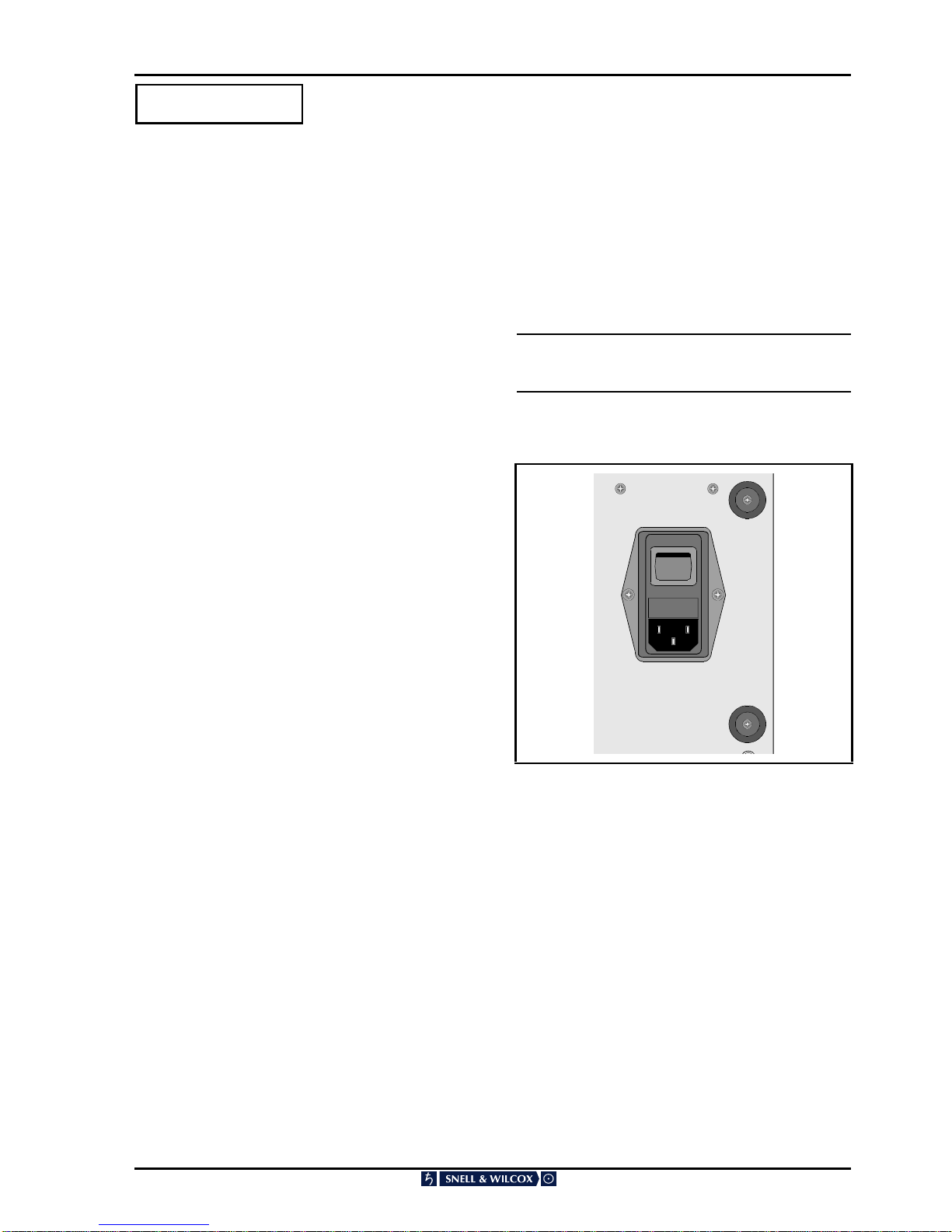
Power
Mains Supply 85 V to 264 V AC 50/60 Hz
Power Consumption 280 W
Mechanical
Temperature Range 0° to 35° C operating
Cooling Filtered Axial fan
Case Type 4RU Rack Mounting
Dimensions 483 mm x 514 mm x 177 mm (w,d,h)
Weight 24 kg