CYP CDPS-US100R Installation manual

CDPS-US100R
HDMI 4K UHD Scaler
Operation Manual
Operation Manual


DISCLAIMERS
The information in this manual has been carefully checked and
is believed to be accurate. Cypress Technology assumes no
responsibility for any infringements of patents or other rights of third
parties which may result from its use.
Cypress Technology assumes no responsibility for any inaccuracies
that may be contained in this document. Cypress also makes no
commitment to update or to keep current the information contained
in this document.
Cypress Technology reserves the right to make improvements to this
document and/or product at any time and without notice.
COPYRIGHT NOTICE
No part of this document may be reproduced, transmitted,
transcribed, stored in a retrieval system, or any of its part translated
into any language or computer le, in any form or by any means—
electronic, mechanical, magnetic, optical, chemical, manual, or
otherwise—without express written permission and consent from
Cypress Technology.
© Copyright 2015 by Cypress Technology.
All Rights Reserved.
TRADEMARK ACKNOWLEDGMENTS
All products or service names mentioned in this document may be
trademarks of the companies with which they are associated.

SAFETY PRECAUTIONS
Please read all instructions before attempting to unpack, install or
operate this equipment and before connecting the power supply.
Please keep the following in mind as you unpack and install this
equipment:
• Always follow basic safety precautions to reduce the risk of re,
electrical shock and injury to persons.
• To prevent re or shock hazard, do not expose the unit to rain,
moisture or install this product near water.
• Never spill liquid of any kind on or into this product.
• Never push an object of any kind into this product through any
openings or empty slots in the unit, as you may damage parts
inside the unit.
• Do not attach the power supply cabling to building surfaces.
• Use only the supplied power supply unit (PSU). Do not use the PSU
if it is damaged.
• Do not allow anything to rest on the power cabling or allow any
weight to be placed upon it or any person walk on it.
• To protect the unit from overheating, do not block any vents or
openings in the unit housing that provide ventilation and allow for
sufcient space for air to circulate around the unit.
REVISION HISTORY
VERSION NO. DATE (DD/MM/YY) SUMMARY OF CHANGE
VR0 28/01/16 First Release

CONTENTS
1. Introduction............................................ 1
2. Applications........................................... 1
3. Package Contents ................................ 1
4. System Requirements............................ 1
5. Features.................................................. 2
6. Operation Controls and Functions....... 3
6.1 Front Panel ........................................3
6.2 Rear Panel.........................................4
6.3 Remote Control................................5
6.4 OSD Menu.........................................5
6.5 IR Cable Pin Assignment..................8
6.6 RS-232 Protocol.................................8
6.7 RS-232 and Telnet Commands .......9
6.8 Telnet Control .................................11
6.9 WebGUI Control .............................13
6.9.1 Scaler Settings .......................13
6.9.2 System Settings......................13
7. Connection Diagram .......................... 14
8. Specications ...................................... 15
8.1 Technical Specications ...............15
8.2 Supported Resolutions...................16
8.3 CAT5e/6/7 Cable Specications..17
9. Acronyms ............................................. 18

1
1. INTRODUCTION
The HDMI 4K UHD Scaler is designed to extend and upscale HDMI
signal on to two HDMI output displays and one analog audio
simultaneously. It supports 4K2K, 3D, 36-bit Deep Color, Hi-Def. lossless
audio and other features dened by the latest HDMI specications.
Allowing uncompressed video and audio, as well as bi-directional IR
control, RS-232 pass-through, also LAN serving from a single CAT5e/6/7
cable over 100m of distance. The management of source/sink
scenarios can be operated easily through on-panel buttons, OSD, IR
remote control, RS-232 and WebGUI control. The Power over Cable
(PoC) function can power compatible receivers, providing greater
exibility in installations.
2. APPLICATIONS
• Extending incoming signal through CAT5e/6/7 to HDMI outputs
• Scale up HDMI input low resolution video on High-Denition display
• Scale down HD signal down monitor
• Lecture room/showroom/Meeting room/Classroom display and
control
• Public Commercial Display extension
3. PACKAGE CONTENTS
• 1×HDMI 4K UHD Scaler
• 2×Terminal Block Jacks
• 1×IR Extender Cable
• 1×IR Blaster Cable
• 1×Remote Control with Battery
• 1×24 V/1.25 A DC Power Adaptor
• 1×Operation Manual
4. SYSTEM REQUIREMENTS
HDBaseT compatible Transmitter input and PS3/Blu-ray player and
output HDMI TV/Display with connection cables.

2
5. FEATURES
• HDMI with 3D pass through supported, and HDCP compliant
• Supports HDTV resolutions up to 4K2K (3840×2160@24/25/30,
3840×2160@50/60 YUV420 & 4096×2160@24/25/30)
• Supports scale down HD resolution on to monitor/display
• Supports data rate from 300Mbps to 3Gbps and Deep Color up to
1080p 36-bit
• Supports simultaneous HDMI outputs with different resolution setting
• Extend HDMI, IR, RS-232 signal up to 100m through CAT5e/6/7 cable
• Supports Balanced audio and bi-directional IR control
• Supports Ethernet transmission rate up to 100Mbps
• Supports OSD, on-panel, Remote, RS-232 and WebGUI control
Note: This system was tested with CAT6/23AWG cable; result may vary
with cable of a different specication.

3
6. OPERATION CONTROLS AND FUNCTIONS
6.1 Front Panel
POWER
MENU
ENTER UHD SCALER
HDMI
HDBaseT
+
-
1 2 3 4 5 6
1POWER & LED: Press this button to turn ON the device or set the
device to standby mode. The LED will illuminate in red when switch
to ON. This device contains power last memory and therefore,
when the power is connected the device will switch to ON/
Standby according to the last status.
2IR WINDOW: This IR Receiver receives the remote control signal from
the packaged included remote control only with IR frequency at
38kHz.
3MENU: Press this button to enter into OSD menu.
Note: When press “MENU”, then press “+”, resolution will set to
XGA60; When press “MENU”, then press “-”, resolution will set to
720p60;
4ENTER: Press this button to select an OSD selection and press it
again to conrm.
5+/-: Press these buttons to move up/down in the OSD selection.
6HDBaseT/HDMI LEDs: When source signal came with HDBaseT or
HDMI, Indicate LED will turn on.

4
6.2 Rear Panel
12
HDMI OUT HDMI IN IR CAT5e/6/7
IN
AUDIO OUT
RS-232
SERVICELAN
INOUT
RX
TX
-
++
-
LR
DC 24V
1 2 5 6 7 8 9 1043
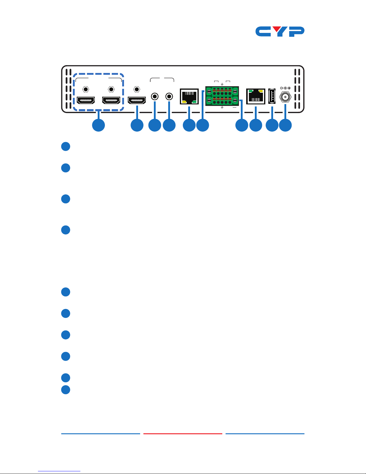
1HDMI OUT 1~2: Connect to HDMI TV/display or HD Amplier for
output image and or audio display.
2HDMI IN: Connect from source equipment such as Blu-ray/DVD/
PS3 players, Set-Top-Box or any HDMI equipped source device for
input signal sending.
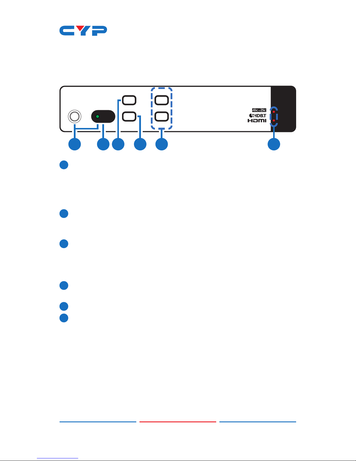
3IR OUT: Connect to the supplied IR Blaster cable for IR signal
transmission. Place the IR Blaster in direct line-of-sight of the
equipment to be controlled.
4IR IN: Connect the supplied IR Receiver cable for IR signal
reception. Ensure that remote being used is within the direct line-
of-sight of the IR Extender.
Note: Both IR IN and IR OUT signal are sending through CAT5e/6/7
cable and therefore, it does not accept the remote signal
included in this package.
5CAT5e/6/7 IN: Connect to the Transmitter unit with a single
CAT5e/6/7 cable for receiving all data signals.
6AUDIO OUT: Connect to active speaker or audio receiver for audio
signal output.
7RS-232: This slot is to connect with D-Sub 9-pin cable from device
equipment for receiving RS-232 commands.
8LAN: Connect to an active network for LAN services, WEBGUI, and
Telnet control with HDBaseT.
9SERVICE: This slot is reserved for manufacture use only.
10 DC 24V: Connect the adaptor with power cord included in the
package and connect to AC wall outlet for power supply.

5
6.3 Remote Control
1POWER: Press to turn on the unit or turn to
standby mode.
2MENU: Press to enter OSD menu page.
3UP/DOWN/LEFT/RIGHT: When Entering
Menu page, use those UP/DOWN keys
to select up/ down, and Use LEFT/RIGHT
key to browse selection.
4ENTER: When entering menu page, use
this button to enter next layer or conrm
selecting.
5HDMI INPUT: Press to switch to HDMI input
signal.
6HDBaseT INPUT: Press to switch to HDBaseT input signal.
7720P: Press to scaling to 720@60 resolution.
81080P: Press to scaling to 1080@60 resolution.
94K: Press to scaling to 4K resolution.
6.4 OSD Menu
MAIN MENU SUB MENU DESCRIPTION DEFAULT
Input Source HDMI Input source signal
selection
HDMI
HDBaseT
Output Format HD Pass-through,
480i@60, 480p@60,
576i@50, 576p@50,
720p@50, 720p@60,
1080i@50, 1080i@60,
1080p@50, 1080p@60,
1080p@24
1080p60
POWERMENU
HDBaseT
4K720P 1080P
ENTER
HDMI
INPUT
CR-150
2
3
1
4
56
7
8
9

6
MAIN MENU SUB MENU DESCRIPTION DEFAULT
Output Format
(Cont.)
4K2K 2048×1080p@24,
2048×2080p@50,
2048×1080p@60,
2048×1152p@60,
3840×2160p@24,
3840×2160p@25,
3840×2160p@30,
4096×2160@24
1080p60
PC-1 640×480@60,
640×480@72,
640×480@75,
800×600@60,
800×600@72,
800×600@75,
1024×768@60,
1024×768@72,
1024×768@75
PC-2 1280×768@60,
1280×800@60,
1280×960@60,
1280×1024@60,
1360×768@60,
1366×768@60,
1400×1050@60,
1440×900@60,
1600×900@60,
1600×1200@60,
1920×1200@60
NATIVE
OSD Menu Timer 10 Sec OSD Menu appearing
time
30Sec
30 Sec
60 Sec
OSD Info Banner ON OSD Info Banner
showing on screen
ON
OFF
Aspect Ratio 4:3 Adjust the Aspect
Ration of Screen
FOLLOW
16:9
FOLLOW
DHCP ON Turn DHCP on and off OFF
OFF

7
MAIN MENU SUB MENU DESCRIPTION DEFAULT
Network Status IP Status Static, DHCP Static
MAC Address Show Unit MAC
address
IP Address Show Current IP
address
192.168.1.50
Subnet Mask Show Subnet Mask 255.255.255.0
Gateway Show Gateway 192.168.1.254
System Info Input Resolution Show Input Resolution
Output
Resolution
Show Output
Resolution
Input Format Show Input Source
format
Input HDCP
Status
Detect Input HDCP
status
Input Audio
Sample Rate
Show Input Audio
sample rate
Video Color
Space
Show video color
space status
Software
Revision
Show software version
OSD Revision Show OSD version
Factory Default When Select into
the page, after
press Enter, the OSD
submenu will show
“ON”, press Enter
again to conrm
selection, press any
other key could
cancel it.

8
6.5 IR Cable Pin Assignment
3
1
2
3
2
1
IR Blaster
Power
IR Signal
NC
IR Signal
Power
Grounding
IR Extender
6.6 RS-232 Protocol
RECEIVER
►
◄
REMOTE CONTROLLER
Pin Assignment Pin Assignment
1 NC 1 NC
2Tx 2Rx
3Rx 3Tx
4 NC 4 NC
5 GND 5 GND
6 NC 6 NC
7 NC 7 NC
8 NC 8 NC
9 NC 9 NC
Baud Rate: 115200bps
Data bit: 8 bits
Parity: None
Flow Control: None
Stop Bit: 1

9
6.7 RS-232 and Telnet Commands
COMMAND DESCRIPTION PARAMETER
Help Display all available
commands
NONE
Help N Display command
description
N=command name
PWON Power on NONE
PWOFF Power off NONE
PWSTA Display power status NONE
VFmtRes Display format status NONE
VFmtRes N Set output video format to
any resolution 480i ~ 4K2K
N=0~42, 254
0=Pass Through
1=640×480p@60
2=720×480i@60
3=720×480p@60
4=1280×720p@60
5=1920×1080@i60
6=1920×1080p@60
7=720×576i@50
8=720×576p@50
9=1280×720p@50
10=1920×1080i@50
11=1920×1080p@50
12=1920×1080p@24
13=1920×1080p@25
14=1920×1080p@30
15=640×480p@72
16=640×480p@75
17=800×600p@60
18=800×600p@72
19=800×600p@75
20=1024×768p@60
21=1024×768p@72
22=1024×768p@75
23=1280×768p@60
24=1280×800p@60
25=1280×960p@60
26=1280×1024p@60
27=1360×768p@60
28=1366×768p@60
29=1400×1050p@60
30=1440×900p@60

10
COMMAND DESCRIPTION PARAMETER
VFmtRes N Set output video format to
any resolution 480i ~ 4K2K
31=1600×900p@60
32=1600×1200p@60
33=1920×1200p@60
34=2048x1080p24
35=2048x1080p50
36 = 2 0 4 8 x1080p6 0
37=2048x1152p60
38=3840x2160p24
39 =38 40x2160 p25
40=3840x2160p30
41=4096x2160p24
42=4096x2160p25
254=Native
Input N Set input source to HDMI/
HDBT
N= HDMI, HBDT
IPCFG Display IP address
congure
NONE
IPDHCP N Set DHCP mode on and
reset telnet
N=on, off, sta
IPStatic xxx.xxx.
xxx.xxx xxx.xxx.
xxx.xxx xxx.xxx.
xxx.xxx
Set static IP address,
Netmask and Gateway
X=0~255
IPQuit Telnet logout NONE
IPAddUser N N1 Add user of telnet N=(User name) 0~9, a~z or
A~Z (Up to 20 character)
N1=(Password) 0~9, a~z or
A~Z (Up to 20 character)
IPDelUser N Delete user of telnet N=User name
IPPort N Set telnet port N=1~65535
IPLogin N Set telnet login status N=on, off, sta
IPTimeout N Set telnet idle timeout
times.
N=1~60000(second)
Aspect N Set Aspect function N=16:9, 4:3, follow
Factory Set back to default settings NONE
Note: Any commands will not be executed unless followed by a
carriage return. Commands are case-sensitive.

11
6.8 Telnet Control
Before attempting to use the Telnet control, please ensure that both
the Matrix (via the 'LAN /CONTROL' port) and the PC/Laptop are
connected to the same active networks.
To access the Telnet control in Windows 7, click on the 'Start' menu
and type "cmd" in the Search eld then press enter.
Under Windows XP go to the 'Start' menu and click on "Run", type
"cmd" with then press enter.
Under Mac OS X, go to Go→Applications→Utilities→Terminal
See below for reference.
Once in the command line interface (CLI) type "telnet", then the IP
address of the unit and "23", then hit enter.

12
This will bring us into the unit which we wish to control. Type "help" to
list the available commands.
Note: Commands will not be executed unless followed by a carriage
return. Commands are case-sensitive. If the IP is changed then the IP
Address required for Telnet access will also change accordingly.

13
6.9 WebGUI Control
On a PC/Laptop which is connected to an active network system,
open a web browser and type device’s IP address (available from
OSD menu) on the web address entry bar. The browser will display the
device’s Scaler settings and system Settings.
6.9.1 Scaler Settings
Click on 'Scaler Settings' to Switch input Source or output format.
6.9.2 System Settings
Click on 'System Settings' to Change the network setting, control
power on/off or reset system.

14
7. CONNECTION DIAGRAM
12
HDMI OUT HDMI IN IR CAT5e/6/7
IN
AUDIO OUT
RS-232
SERVICE
DC 24V
LAN
INOUT
RX
TX
-
++
-
LR
1.5m
60°
RS-232 In
LAN
HDMI In
HDMI to CAT5e/6 with LAN/IR/RS232
Transmitter
7m3m 3m
60°
m
m
m
DVD/Blu-ray Player Games Console
Active Speakers
IR Blaster
IR Extender
HDTV HDTV
LAN ConnectionHDMI Input
HDMI Input
CAT 5e/6/7 Input
Analog Audio Output
Power
Supply
LAN Connection
RS-232 Connection
Internet
Connected
Router
HDMI Outputs
TX
RS-232 Equipped
PC/Laptop

15
8. SPECIFICATIONS
8.1 Technical Specications
Video Bandwidth 340 MHz/10.2 Gbps
Input Ports 1×HDMI, 1×CAT5e/6/7, 1×LAN (RJ-45), 1×IR
(3.5mm), 1×RS-232 (Terminal Block), 1×USB
(Service only)
Output Ports 2×HDMI, 1×Stereo Audio (Terminal Block),
1×IR (3.5mm)
HDMI Resolutions VGA~WUXGA (RB), 408i~1080p@24/50/60,
4K@24/25/30
IR Frequency 30~50 kHz
Baud Rate 115200 bps
HDMI Cable Distance 10 m@1080p/8-bit, 10 m@1080p/12-bit,
5 m@4K
Power Supply 24 V/1.25 A DC (US/EU standards, CE/FCC/
UL certied)
ESD Protection Human body model:
±8 kV (air-gap discharge)
±4 kV (contact discharge)
Dimensions 219 mm (W)×156 mm (D)×43 mm (H)/
Jack Excluded
219 mm (W)×164.3 mm (D)×51 mm (H)/
Jack Included
Weight 1136 g
Chassis Material Metal
Color Black
Operating Temperature 0˚C~40˚C/32˚F~104˚F
Storage Temperature −20˚C~60˚C/−4˚F~140˚F
Relative Humidity 20~90% RH (non-condensing)
Power Consumption 15 W/25 W (PoC)
Other manuals for CDPS-US100R
1
Table of contents
Other CYP Media Converter manuals