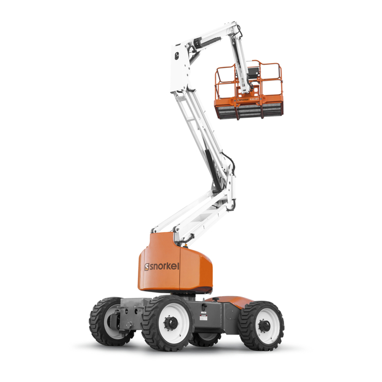
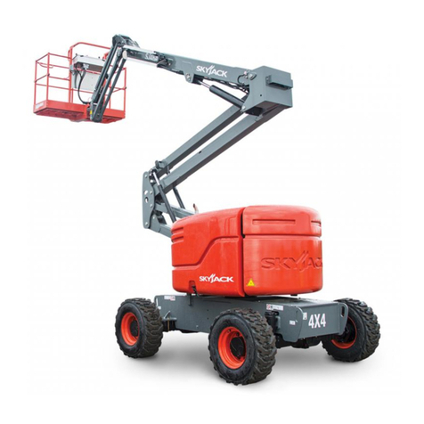
Snorkel 460SJ User manual

September 2021
Part Number 1433685
MANUAL
OPERATOR’SOPERATOR’S
ANSI/CSA/CE/AS/NZS
Serial number 000000 and after
Replaces December 2020

The aerial platform is not electrically insulated. Death or serious injury will result from contact
with, or inadequate clearance from, an energized conductor.
Do not go closer than the minimum safe approach distance as defined by the Minimum Safe
Approach Distance sections in Chapter 3–Safety.
Regard all conductors as energized.
Allow for electrical wire sag and aerial platform sway.
If the platform, booms, or any part of the aerial platform contacts a high-voltage electrical conductor,
the entire machine can become electrically charged.
If that happens, remain on the machine and do not contact any other structure or object. This includes
the ground, adjacent buildings, poles, and any other objects that are not part of the aerial platform.
Such contact could make your body a conductor to the other object, creating an electrical shock hazard
resulting in death or serious injury.
If an aerial platform is in contact with an energized conductor the platform operator must warn ground
personnel in the vicinity to stay away. Their bodies can conduct electricity creating an electrical shock
hazard resulting in death or serious injury.
Do not approach or leave the aerial platform until the electricity has been turned off.
Do not attempt to operate the lower controls when the platform, booms, or any part of the aerial plat-
form is in contact with a high-voltage electrical conductor or if there is an immediate danger of such
contact.
Personnel on or near an aerial platform must be continuously aware of electrical hazards, recognizing
that death or serious injury can result from contact with an energized conductor.
California
Proposition 65 Warning
Battery posts, terminals, and related accessories contain
lead and lead components, chemicals known to the
State of California to cause cancer and birth defects or
other reproductive harm. Wash hands after handling.
California
Proposition 65 Warning
Diesel and gasoline engine exhaust and some of its con-
stituents are known by the State of California to cause
cancer, birth defects or other reproductive harm.

460SJ – 1433685
Do NOT Operate in
Windy or Gusty Conditions
Do NOT Add Anything That
Will Increase Wind Loading
Do NOT Operate Outside
During a Thunderstorm
Do NOT Go Closer Than The
Minimum Safe Approach Distance
Do NOT Operate a Stowed
MEWP on Rough or Uneven Terrain
Do NOT Operate an Elevated MEWP
Near Any Drop-off or Hole
Do NOT Operate an Elevated
MEWP on Rough or Uneven Terrain
Do NOT Drive an Elevated MEWP on
Soft, Uneven or Sloping Surfaces
Do NOT Exceed The Maximum
Allowable Manual Side Force
Do NOT Operate The MEWP
Without Sufficient Clearance
Do NOT Use The MEWP As a
Lifting Tool or Crane
Do NOT Operate a Stowed MEWP
Near Any Drop-off or Hole
Do NOT Allow Ground Personnel
Near the MEWP During Operation
Do NOT Carry Loads That
Extend Beyond The Guardrails
Do NOT Lower The Platform Without
Checking For Obstructions
Do NOT Raise The Platform Without
First Checking For Obstructions
Do NOT Exceed The Platform
Rated Work Load
Do NOT Climb on The MEWPDo NOT Operate an MEWP From
Trucks, Trailers, or Similar Equipment
Do NOT Operate an MEWP With
Tires That Are in Poor Condition
Do NOT Operate an MEWP That is
Damaged or Not Functioning Properly
Do NOT Engage In Any
Form of Horseplay
Do NOT Climb on
The Guardrails
Do NOT Strike or Bump Stationary
Objects With an Elevated MEWP
Do NOT Strike or Bump Stationary
Objects With a Stowed MEWP
Do NOT Operate an MEWP
While Physically Impaired
Do NOT Leave the MEWP
With The Key In It
DANGER

Figure 1 – Correct Wheel Orientation
Figure 2 – Wheel Position Decal
The distance between the outer edge of the right wheel
to the outer edge of the left wheel should be 2390mm
(94 in) when the wheels are correctly orientated. Refer
to Figure 3.
WARNING
SAFETY NOTICE
PLEASE READ BEFORE USE
If this machine has been transported in a container the wheels will have been
flipped to get it into the container. This will make the machine narrower than the
design intent. The machine may be driven with the wheels flipped to load &
unload but only ever when in the stowed position. The machine must not be
used for a job of work until the wheels have been flipped back round to their
correct position.
To flip the wheel back to the correct orientation (refer to
Figure 1), use the following instructions.
1. Safely jack the machine.
2. Loosen the 9 retaining lug nuts.
3. Safely remove the wheel from the hub.
4. Flip the wheel 180° so that decal 106171-003 is facing
on the inside of the wheel. Refer to Figure 2.
5. Safely fit the wheel back onto the hub.
6. Hand tighten the 9 retaining lug nuts and lower the
machine from the jack.
7. Dry torque the lug nuts to 150 ft lbs in a non-circular
pattern.
Figure 3 – Wheel Position Distance
180°
FOR SAFE AND STABLE
OPERATION, THIS WHEEL
MUST BE MOUNTED SO
THAT THIS DECAL FACES
TOWARD THE INSIDE
OF THE MACHINE.
DANGER
106717-003
2190mm
2390mm
TRANSPORTATION POSITION
WORKING/ELEVATING POSITION

460SJ – 1433685
Warning
All personnel shall carefully read, understand and follow all safety rules and operating instructions
before operating or performing maintenance on any Snorkel aerial work platform.
Electrocution Hazard Tip Over Hazard Collision Hazard Fall Hazard
THIS MACHINE IS
NOT INSULATED!
NEVER elevate the platform
or drive the machine while
elevated unless the machine
is on a firm, level surface
NEVER position the platform
without first checking for
overhead obstructions or
other hazards.
NEVER climb, stand, or sit
on platform guardrails or
midrail.
USE OF THE AERIAL WORK PLATFORM: This aerial work platform is intended to lift persons and his tools as well as the
material used for the job. It is designed for repair and assembly jobs and assignments at overhead workplaces (ceilings,
cranes, roof structures, buildings etc.). Uses or alterations to the aerial work platform must be approved by Snorkel.
THIS AERIAL WORK PLATFORM IS NOT INSULATED! For this reason it is imperative to keep a safe distance from live
parts of electrical equipment!
Exceeding the specied permissible maximum load is prohibited! See “Platform Capacity” for details.
The use and operation of the aerial work platform as a lifting tool or a crane is prohibited!
NEVER exceed the manual force allowed for this machine. See “Manual Force” for details.
DISTRIBUTE all platform loads evenly on the platform.
NEVER operate the machine without rst surveying the work area for surface hazards such as holes, drop-os, bumps, curbs,
or debris; and avoiding them.
OPERATE machine only on surfaces capable of supporting wheel loads.
NEVER operate the machine when wind speeds exceed this machine’s wind rating. See “Beaufort Scale” for details.
Do not operate the aerial platform in windy or gusty conditions. Do not add anything to or take anything into the aerial platform
that will increase the wind loading such as billboards, banners, flags, etc.
IN CASE OF EMERGENCY push EMERGENCY STOP switch to deactivate all powered functions.
IF ALARM SOUNDS while platform is elevated, STOP, carefully lower platform. Move machine to a rm, level surface.
Climbing up the railing of the platform, standing on or stepping from the platform onto buildings, steel or prefab concrete
structures, etc., is prohibited!
Dismantling the entry gate or other railing components is prohibited! Always make certain that the entry gate is closed!
It is prohibited to keep the entry gate in an open position when the platform is raised!
To extend the height or the range by placing of ladders, scaolds or similar devices on the platform is prohibited!
NEVER perform service on machine while platform is elevated without blocking elevating assembly.
INSPECT the machine thoroughly for cracked welds, loose or missing hardware, hydraulic leaks, loose wire connections, and
damaged cables or hoses before using.
VERIFY that all labels are in place and legible before using.
NEVER use a machine that is damaged, not functioning properly, or has damaged or missing labels.
To bypass any safety equipment is prohibited and presents a danger for the persons on the aerial work platform and in its
working range.
NEVER charge batteries near sparks or open ame. Charging batteries emit explosive hydrogen gas.
Modications to the aerial work platform are prohibited or permissible only at the approval by Snorkel.
AFTER USE, secure the work platform from unauthorized use by turning the keyswitch o and removing key.
The driving of MEWP’s on the public highway is subject to national trac regulations.
Certain inherent risks remain in the operation of this machine despite utilizing proper design practices and safeguarding.
Harness attachment points are provided in the platform and the manufacturer recommends the usage of a fall restraint
harness, especially where required by national safety regulations.
Care must be taken to ensure that the machines meets the requirements of stability during use, transportation, assembly,
dismantling when out of service, testing, or foreseeable breakdowns.
In the event of an accident or breakdown see “Emergency Operation.” Do not operate the aerial platform if it is damaged or not
functioning properly. Qualied maintenance personnel must correct the problem before putting the aerial platform back into service.
SAFETY RULES

460SJ – 1433685

460SJ – 1433685
Table of Contents
Electrical Danger ............................ Inside Front Cover
Proposition 65 Warning .................. Inside Front Cover
Danger Symbols............................. Inside Front Cover
Wheel Orientation Warning ............ Inside Front Cover
Safety Rules ................................... Inside Front Cover
Chapter 1 – Introduction
Aerial Platform Features.............................................1
Options .......................................................................1
Operator’s Manual......................................................1
Safety Alerts ...............................................................1
Operation....................................................................2
Maintenance...............................................................2
Used Material Disposal ...........................................2
Manual of Responsibilities – ANSI..............................2
MEWP Safe Use – AS/NZS........................................3
AS/NZS 1418.10 Commissioning...............................3
CE Compliance...........................................................3
Additional Information.................................................3
Chapter 2 – Specications
Component Identication............................................5
Working Envelope – Single Capacity .........................6
Working Envelope – Dual Capacity............................7
General Specications................................................8
Engine Specications .................................................9
Engine Oil Viscosity....................................................9
Chapter 3 – Safety
Electrocution Hazards .............................................. 11
Minimum Safe Approach Distance – ANSI ............... 11
Minimum Safe Approach Distance – AS/NZS...........12
Platform Capacity .....................................................12
Manual Force............................................................12
Wind Speeds ............................................................12
Prestart Inspection....................................................12
Work Place Inspection and Practices.......................12
Operation..................................................................13
Tip-Over and Falling Hazards...................................13
Electrical System......................................................14
Hydraulic System......................................................14
Engine and Fuel Handling Precautions ....................14
Placards and Decals.................................................15
General Safety Rules ...............................................15
Chapter 4 – Safety Devices
Emergency Stop Controls.........................................17
Emergency Power System .......................................17
Emergency Lowering Knob ......................................17
Ground Operation Switch .........................................18
Platform Foot Switch ................................................18
Guardrails.................................................................18
Fall Protection Anchors.............................................18
Ground Fault Circuit Interrupter................................18
Platform Overload Sensing System..........................18
Boom/Drive Cut-out..................................................19
Tilt Alarm/Warning Lights..........................................19
Engine Protection Systems ......................................19
High Engine Temperature Alarm ...........................19
Low Oil Pressure Alarm ........................................19
Horn..........................................................................19
Drive Motion Alarm ...................................................20
All Motion Alarm........................................................20
Flashing Lights .........................................................20
Driving Lights............................................................20
Platform Work Lights ................................................20
Snorkel Guard ..........................................................20
Chapter 5 – Gauges and Displays
Diagnostic Center Display ........................................21
Platform Overload/Tilt Warning Lights......................21
Dual Platform Capacity System................................21
Engine Warning Lights .............................................21
Fuel...........................................................................22
Fluid Level and Temperature Gauge ........................22
Engine Oil.................................................................22
Chapter 6 – Controls
Battery Disconnect Switch........................................23
Lower Controls .........................................................23
Start/Emergency Power/Ground Operation Switch ...23
Emergency Stop Button ........................................24
Controls Selector Switch.......................................24
Rotation Switch .....................................................24
Boom Elevation Switch .........................................24
Boom Extension Switch ........................................24
Jib Articulation Switch ...........................................25
Platform Level Switch ...........................................25
Platform Rotation Switch.......................................25
Platform Overload Warning Light ..........................25
Dual Platform Capacity System ............................25
Tilt Alarm ...............................................................25
Diagnostic Center Display.....................................25
Hydraulic Oil Warm-Up Switch..............................25
Circuit Breaker Reset Buttons ..................................25
Upper Controls .........................................................26
Start Switch...........................................................26
Emergency Stop Button ........................................26
Drive Joystick........................................................26
Drive Range Switch ..............................................26
Boom Joystick.......................................................27
Boom Extension Joystick ......................................27
Jib/Platform Rotate Joystick..................................27
Platform Level Switch ...........................................27
Emergency Power Switch .....................................27
Horn Switch...........................................................28
Engine Speed Switch............................................28
Override Switch.....................................................28
Platform Foot Switch.............................................28
Platform Overload Warning Light ..........................28
Dual Platform Capacity System ............................28
Tilt Alarm ...............................................................28
AC Generator Switch ............................................28
Hydraulic Oil Warm-Up Switch..............................28
Driving and Platform Work Lights.............................29

Table of Contents
460SJ – 1433685
Chapter 7 – Prestart Inspection
Operator’s Manual Holder ........................................31
Engine ......................................................................31
Oil Level ................................................................31
Coolant..................................................................31
Radiator ................................................................32
Fuel Tank...............................................................32
Fuel Line ...............................................................32
Electrical System......................................................32
Battery Terminals ..................................................33
Cables and Wiring Harness ..................................33
Hydraulic System......................................................33
Fluid Level.............................................................33
Fluid Filter .............................................................33
Hoses, Tubes, and Fittings ...................................33
Tires and Wheels......................................................34
Lower Control Station...............................................34
Operating Controls................................................34
Emergency Stop ...................................................35
Emergency Power.................................................35
Diagnostic Center Display ........................................35
Emergency Lowering................................................35
Flashing Lights .........................................................35
Structures .................................................................36
Weldments ............................................................36
Boom Slide Pads ..................................................36
Fasteners ..............................................................36
Upper Control Station...............................................36
Guardrail System ..................................................36
Fall Protection Anchors .........................................37
Operating Controls................................................37
Emergency Stop ...................................................38
Emergency Power.................................................38
Horn Switch...........................................................38
Snorkel Guard.......................................................38
Electrical Power Outlet..........................................38
Level Sensor.............................................................39
Panel Carrier ............................................................39
All Motion Alarm........................................................39
Sandblast Protection Kit ...........................................39
Air Line to Platform...................................................39
Driving and Platform Work Lights.............................39
Tow Kit......................................................................39
Platform Glazier Package.........................................40
Platform Welder........................................................40
Drive Motion Alarm ...................................................40
Placards and Decals.................................................40
Prestart Inspection Checklist....................................45
Inspection and Maintenance Schedules...................46
Chapter 8 – Operation
Cold Weather Start-Up .............................................47
Hydraulic System Cold Weather Warm-Up .............47
Hydraulic System Warm-Up Switch ......................47
Manually Warming The Hydraulic System ............47
Preparing for Operation............................................48
Lower Controls .........................................................48
Upper Controls .........................................................48
Engine Speed Switch............................................49
Boom Operation....................................................49
Jib and Boom Simultaneous Operation ................49
Dual Platform Capacity System ............................49
Driving and Steering .............................................50
Drive Speeds ........................................................51
Pivoting Front Axle....................................................51
Machine in Stowed Position..................................51
Machine Not in Stowed Position ...........................51
Boom and Turntable Position/Axle and Drive Speeds..51
Drive Motion Alarm ...................................................51
Boom/Drive Cut-out..................................................51
Platform Overload Sensing System..........................51
Snorkel Guard ..........................................................52
Override Switch ........................................................52
Gradeability ..............................................................52
Percent vs. Degree of Slope .................................53
Driving on a Slope.................................................53
Calculating Percent Grade....................................53
Machine Gradeability ............................................54
Electrical Power Outlet .............................................54
AC Generator ...........................................................54
Panel Carrier ............................................................54
Platform Capacity..................................................54
Air Line .....................................................................55
Driving Lights............................................................55
Platform Work Lights ................................................55
Platform Glazier Package.........................................55
Platform Capacity..................................................56
Platform Welder........................................................56
Platform Capacity..................................................56
After Use Each Day..................................................56
Chapter 9 – Stowing and Transporting
Stowing.....................................................................57
Transporting .............................................................57
Driving...................................................................57
Winching ...............................................................58
Hoisting .................................................................58
Securing for Transport ..........................................59
Storage.....................................................................60
Chapter 10 – Emergency Operation....... 61
Emergency Power System .......................................61
Lower Controls .........................................................61
Upper Controls .........................................................61
Override Switch ........................................................62
Emergency Lowering................................................62
Towing ......................................................................63
Chapter 11 – Troubleshooting
Troubleshooting Chart ..............................................65
Appendix A – Glossary
Appendix B – EC Declaration of Conformity
Appendix C – Inspection Checklists
Limited Warranty

460SJ – 1433685 1
Chapter 1 – Introduction
Aerial Platform Features
The aerial platform is a boom-supported elevating work
platform used to raise personnel, their tools, and material
to the workstation. The booms are raised and lowered with
hydraulic cylinders. Hydraulic motors on the drive wheels
provide power to move the aerial platform.
The standard machine includes the following features:
• Proportional boom lift, rotate, and drive controls
• Four wheel hydrostatic drive
• Pivoting front axle
• Foam filled tires
• High engine temperature shut down
• Low oil pressure shut down
• Hour meter
• Horn
• Boom/drive cut-out – machines manufactured after
March 2021
• Flashing light
• Drive motion alarm
• Snorkel Guard
• Platform overload system
• Tie-down/lifting lugs
• 5 degree tilt alarm ANSI
• 3.5 degree tilt alarm CE/AS/NZS
• Hydraulic oil level gauge
• Hydraulic oil cooler
• Diagnostic center display
• Battery operated emergency operating system
• Manual lowering valve
• 360 degree continuous turntable rotation
• Saloon entry doors (rear) and two gravity gates (left
and right side)
• Two fall protection anchors
• Built-in panel carrier
• AC 110 V electrical outlet with GFCI at platform
• Deutz D2.9 L4 diesel engine
• Swing-out engine tray
• Five year limited warranty
The machine may be powered with one of the following
engines.
• Deutz TCD 2.9 L4 diesel engine
• Kubota V1505-TE diesel engine
The aerial platform has been manufactured, when ap-
plicable, to conform to all applicable requirements of the
following organizations:
• Occupational Safety and Health Administration
(OSHA)
• American National Standards Institute (ANSI)
Options
The following options may be provided on the machine:
• Dual platform capacity system – 600 and 1,000 lb
• Airline to platform
• Non-marking tires
• AS generator 110V/240V 2 kW
• Second battery 12V 1000 CCA
• All motion alarm
• Cold weather start kit
• Hydraulic fluid warm-up system
• Driving lights
• Tow package
• Sandblast protection kit
• 39″x 96″(99 cm x 243 cm) 600 lb (272 kg) capacity
steel platform with rear swing gate and two gravity
gates (right and left side)
• Platform work lights – LED
• Platform welder – 275 amp
• Platform glazier package
• European conformity (CE) compliance
• Australian/New Zealand Standards
(AS/NZS) compliance
• Canadian Standards Association (CSA) compliance
Operator’s Manual
This manual provides information for safe and proper
operation of the aerial platform. Some information in this
manual refers to options that may or may not be on your
machine. Read and understand the information in this
Operator’s Manual before operating the aerial platform
on the job.
Additional copies of this manual may be ordered from
Snorkel. Supply the model and manual part number from
the front cover to assure that the correct manual will be
supplied.
All information in this manual is based on the latest
product information at the time of publication. Snorkel
reserves the right to make product changes at any time
without obligation.
Safety Alerts
A safety alert symbol is used throughout this manual to
indicate danger, warning, and caution instructions. Follow
these instructions to reduce the likelihood of personal
injury and property damage. The terms danger, warning,
and caution indicate varying degrees of personal injury
or property damage that can result if the instruction is
not followed.
Danger
Indicates an imminently hazardous situation which,
if not avoided, will result in death or serious injury.
This signal word is to be used in the most extreme
situations.
Warning
Indicates a potentially hazardous situation which, if
not avoided, could result in death or serious injury.

Chapter 1 – Introduction
2 460SJ – 1433685
Caution
Indicates a potentially hazardous situation which, if
not avoided, may result in minor or moderate injury.
It may also be used to alert against unsafe practices.
Notes
Notes are used to provide special information or helpful
hints to assist in aerial platform operation, but do not
indicate a hazardous situation.
Operation
The aerial platform has built-in safety features and has
been factory tested for compliance with Snorkel specifi-
cations and industry standards. However, any personnel
lifting aerial platform can be potentially dangerous in the
hands of untrained or careless operators.
Warning
The potential for an accident increases when the
aerial platform is operated by personnel who are not
trained and authorized. Death or serious injury could
result from such accidents. Read and understand the
information in this manual and on the placards and
decals on the machine before operating the aerial
platform on the job.
Training is essential and must be performed by a quali-
fied person.
• Become proficient in knowledge and actual operation
before using the aerial platform on the job.
• The operator must be trained and authorized to per-
form any functions of the aerial platform.
• Operation of the aerial platform must be within the
scope of the machine specifications.
The operator bears ultimate responsibility for following
all manufacturer’s instructions and warnings, regulations
and safety rules of their employer and/or any state or
federal law.
Maintenance
Complete machine inspection consists of periodic visual
and operational checks, along with periodic minor adjust-
ments that assure proper performance. Daily inspection
will prevent abnormal wear and prolong the life of all
systems. The inspection and maintenance schedule
should be performed at the specified intervals and after
prolonged periods of storage before returning the ma-
chine to service. Inspection and maintenance shall be
performed by personnel who are trained and familiar with
mechanical and electrical procedures.
Every person who maintains, inspects, tests, or repairs
the aerial platform must be qualified to do so. Following
the daily prestart inspection in this Operator’s Manual will
help keep the aerial platform in optimum working condi-
tion. Other maintenance functions must be performed
by maintenance personnel who are qualified to work on
the aerial platform.
Caution
Welding current can be very intense. Damage to elec-
tronic components may result. Connect the ground
clamp as close as possible to the area being welded.
Disconnect battery cables and any microprocessors
and engine control modules before welding on the
machine.
If it becomes necessary to weld aerial platform com-
ponents as a method of repair, take all precautions to
prevent damage to electronic circuitry and devices on
the machine. This includes, but may not be limited to,
disconnecting battery cables and electronic devices.
Do not modify this aerial platform without prior written con-
sent of the Snorkel Engineering Department. Modification
may void the warranty, adversely affect stability, or affect
the operational characteristics of the aerial platform.
Used Material Disposal
For proper used material disposal, refer to all applicable
national and/or employer standards before disposal of
any environmentally sensitive material including, but not
limited to, hydraulic fluid, batteries, and battery fluid.
Manual of Responsibilities – ANSI
All owners and users of the aerial platform must read,
understand, and comply with all applicable regulations.
Ultimate compliance to OSHA regulations is the respon-
sibility of the user and their employer.
ANSI publications clearly identify the responsibilities of all
personnel who may be involved with the aerial platform.
A reprint of the “Manual of Responsibilities for Manufac-
turers, Dealers, Owners, Users, Supervisors, Operators,
Occupants, Lessors, Lessees and Brokers of ANSI/SIA
A92.22-2020 Safe Use & ANSI/SIAA92.24-2018 Training
Requirements for the Use, Operation, Inspection, Testing
and Maintenance of Mobile Elevating Work Platforms
(MEWP)” is available from Snorkel dealers or from the
factory upon request.
Copies are also available from:
Scaffold & Access Industry Association
400 Admiral Boulevard
Kansas City, MO 64106 USA

Chapter 1 – Introduction
460SJ – 1433685 3
MEWP Safe Use – AS/NZS
All owners and users of the aerial platform must read,
understand, and comply with all applicable regulations as
stated in AS/NZS 2550.10:2006. Ultimate compliance is
the responsibility of the user and their employer.
AS/NZS 1418.10 Commissioning
Per AS/NZS 1418.10, a machine has been commissioned
upon return to Snorkel of a satisfactory completed Pre-De-
livery and Inspection Record (PDIR). The PDIR inspection
is performed by Snorkel, or it’s agent, before the machine
is delivered to the customer. A completed PDIR form can
be obtained, by request, from the sales agent.
CE Compliance
The aerial work platform meets and exceeds the require-
ments of both EN280:2013 and ANSI A92.5.
Additional Information
For additional information contact your local dealer or
Snorkel at:
Snorkel International
P.O. Box 1160
St. Joseph, MO 64502-1160 USA
1-800-255-0317
http://www.snorkellifts.com
Regional contact information is located on the back cover
of this manual.

Chapter 1 – Introduction
4 460SJ – 1433685

460SJ – 1433685 5
Chapter 2 – Specications
Component Identication
E
Right Side
Chassis
Lower Controls
Diagnostic Display
Upper Controls
Operator’s
Manual Steer Wheels
Left Side
Platform
Main Boom
Tip Boom
Batteries
Engine
Steer Wheels Platform
Foot Switch
Fuel Tank
Rear Front
Rear
Front
Jib
Tie-Down/Lifting Lugs
Rear of Chassis
Tie-Down/Lifting Lugs
Front of Chassis
Fall Protection
Anchors
Battery
Disconnect
Serial Number Placard
On Side of Chassis
Serial Number • Model Number
Tie-Down Lugs
Side of Chassis
Hydraulic Fluid Tank
Hydraulic Fluid Filter
Pivoting
Front Axle
Platform Identication Placard
On Inside Front of Platform
Serial Number • Model Number
Emergency
Lowering Valve
Inside Turntable

Chapter 2 – Specications
6 460SJ – 1433685
Working Envelope – Single Capacity
Feet
(Meters)
20
(6.1)
30
(9.1)
0
40
(12.2)
10
(3.0)
10
(3.0)
20
(6.1)
30
(9.1)
50
(15.2)
40
(12.2)
05
(1.5)
10
(3.0)
55
(16.8)
10
(3.0)
5
(1.5)
15
(4.6)
25
(7.6)
35
(10.7)
45
(13.7)
5
(1.5)
5
(1.5)
15
(4.6)
25
(7.6)
35
(10.7)
45
(13.7)
Maximum Platform Capacity
600 lb (272 kg)

Chapter 2 – Specications
460SJ – 1433685 7
Working Envelope – Dual Capacity
Feet
(Meters)
20
(6.1)
30
(9.1)
0
40
(12.2)
10
(3.0)
10
(3.0)
20
(6.1)
30
(9.1)
50
(15.2)
40
(12.2)
05
(1.5)
10
(3.0)
55
(16.8)
10
(3.0)
5
(1.5)
15
(4.6)
25
(7.6)
35
(10.7)
45
(13.7)
5
(1.5)
5
(1.5)
15
(4.6)
25
(7.6)
35
(10.7)
45
(13.7)
Maximum Platform Capacity
1,000 lb (453.5 kg)
Maximum
Platform
Capacity
600 lb (272 kg)

Chapter 2 – Specications
8 460SJ – 1433685
General Specications
Aerial Platform
Working height 52′10″ (16.10 m)
Maximum platform height 46′10″ (14.27 m)
Horizontal reach 41′(12.50 m)
Main boom
Articulation -16° to +72°
Extension 15′ (4.57 m)
Jib boom
Articulation -65.1° to +70°
Extension 6′6″ (1.98 m)
Turntable rotation 360° continuous
Turning radius, outside 16′7″ (5.05 m)
Turning radius, inside 9′10″ (2.9 m)
Tail swing 34.5″ (87.6 cm)
Wheelbase 7′ 7″(2.3 m)
Ground clearance 12.5″(31.75 cm)
Maximum wheel load 8,700 lb (3,955 kg)
Maximum ground bearing pressure
92 psi (6.43 kg/cm²)
Maximum distributed floor load 275 psf (1,345 kg/m²)
Level sensor setting – ANSI 5 degrees
Level sensor setting – CE/AS/NZS 3.5 degrees
Weight, EVW approximate 17,260 lbs (7,845 kg)
Maximum allowable manual force (side pull)
Per occupant 45 lb (200 N)
Maximum allowable manual force (side pull)
Two occupants total 90 lb (400 N)
Width
Overall width 7′7″(2.31 m)
Transport width – wheels flipped 6′10″ (2.08 m)
Stowed length
Overall length 28′4″(8.63 m)
Transport length 28′9″ (8.76 m)
Stowed height 7′10″ (2.38 m)
Platform
Dimensions
Standard 39″x 96″(99 cm x 243 cm)
Rated work load, standard unrestricted 600 lb (272 kg)
Rated work load, restricted 1,000 lb (453.5 kg)
Rotation 150 degrees
Maximum number of occupants 2 people
Optional AC generator 110 V
Optional AC generator 220 V, 3-phase, 10 kw
Function Speed
Turntable rotation
Booms retracted – ANSI 85 to 95 seconds
Booms retracted – CE/AS/NZS 165 to 175 seconds
Main boom
Up – ANSI 32 to 38 seconds
Up – CE/AS/NZS 50 to 55 seconds
Down – ANSI 32 to 38 seconds
Down – CE/AS/NZS 50 to 55 seconds
Extend 30 to 45 seconds
Retract 30 to 45 seconds
Jib boom
Up 12 to 17 seconds
Down 12 to 17 seconds
Platform rotation 12 to 16 seconds
Platform leveling
Up – ANSI 12 to 22 seconds
Up – CE/AS/NZS 50 to 55 seconds
Down – ANSI 12 to 22 seconds
Down – CE/AS/NZS 50 to 55 seconds
Drive
High, boom down/retracted – ANSI/CE/AS/NZS
Forward 4.25 mph (6.6 km/h)
Reverse 2.75 mph (4.4 km/h)
Low, boom up/extended
ANSI 0.75 mph (1.2 km/h)
CE/AS/NZS 0.6 mph (0.96 km/h)
Drive System
Standard 4WD
Gradeability 50%
Axle front oscillating
Vertical wheel travel 8″ (20.32 cm)
Maximum drive height 46′(14 m)
Tires
Foam filled 355/55 D625, 14 ply
Mass 427.5 lbf (194.3 kg)
Flotation air filled – non-directional 33/16LL500
Minimum weight with wheel 150 lb (68.2 kg)
Electrical System
Voltage 12 V DC negative chassis ground
Source One - 12 V 1000 CCA battery
Hydraulic System
Pressure
System maximum 4,500 psi (31,026 kPa)
Boom circuit maximum 2,900 psi (19994 kPa)
Reservoir capacity 30 US gal (113.5 l)
System capacity 40 US gal (151.4 l)
Maximum operating temperature 200°F (93°C)
Hydraulic fluid recommended
Above -12°C (10°F) ISO VG32
Below -12°C (10°F) ISO VG15
Engine
Diesel Deutz D2.9 L4
Output 49 hp (36.5kw)
Diesel Kubota V1505-TE
Fuel Tank Capacity
Diesel 28 US gal (105.9 l)
Ambient Air Temperature Operating Range
Fahrenheit 0°F to 110°F
Celsius -18°C to 43°C
Maximum Manual Force
Per occupant 45 lb (200 N)
Two occupants 90 lb (400 N)
Maximum Wind Speed
Gust or steady 28 mph (12.5 m/s)
Vibration
Hand/arm less than 2.5 m/sec²
Body less than 0.5 m/sec²
Sound Pressure Level
At work station below 110 dB(A)
Sound Power Level 80 dB LWAd
Group Classication
Heavy Duty – intended life 100,000 load cycles

Chapter 2 – Specications
460SJ – 1433685 9
Engine Specications
Note 1: Refer to the engine manufacturer’s manual for specific fuel recommendations and specifications.
Note 2: Refer to the engine manufacturer’s manual for specific coolant recommendations and specifications.
Note 3: Refer to the engine manufacturer’s manual for specific lubricating oil recommendations and specifications.
Engine Oil Viscosity
Deutz D2.9 L4
Displacement Fuel Grade Coolant Oil
Capacity
177 cu. in.
(2.9 liter)
Oil
Grade
Engine
Diesel Fuel No. 2-D
ASTM D9751
ASTM D6210 (TMCRP 329)
ASTM D6211 (TMCRP 330)
Heavy Duty Coolant Only2
8.45 qt
(8 liter)
API1 CJ-43
ACEA E93
Deutz
D2.9 L4
Output
49 hp
(36.5kw)
SAE 10W-40
SAE 20W-50
SAE 5W-30
SAE 0W-40
SAE 0W-30
SAE 15W-40
SAE 5W-40
SAE 10W-30
45
40
35
30
25
20
15
10
5
0
-5
-10
-15
-20
-25
-30
-35
-40
°C
113
104
95
86
77
68
59
50
41
32
23
14
5
-4
-13
-22
-31
-40
°F
Kubota
V1505-TE
91 cu. in.
(1498 cm3)
Diesel Fuel No. 2-D
ASTM D9751
50% water
50% Antifreeze21.77 gal
(6.7 liter)
API:
CD grade or
higher3
Kubota V1505-TE

Chapter 2 – Specications
10 460SJ – 1433685

460SJ – 1433685 11
Chapter 3 – Safety
Knowledge of the information in this manual, and proper
training, provide a basis for safely operating the aerial plat-
form. Know the location of all controls and how they oper-
ate to act quickly and responsibly in an emergency.
Safety devices reduce the likelihood of an accident.
• Never disable, modify, or ignore any safety device.
• Safety alerts in this manual indicate situations where
accidents may occur.
If any malfunction, hazard or potentially unsafe condition
relating to capacity, intended use, or safe operation is sus-
pected, stop aerial platform operation and seek assistance.
The operator bears ultimate responsibility for following
all manufacturer’s instructions and warnings, regulations
and safety rules of their employer and/or any state or
federal law.
Electrocution Hazards
The aerial platform is made of metal components and is
not insulated. Regard all conductors as energized. Do
not operate outside during a thunderstorm.
Minimum Safe Approach Distance – ANSI
Minimum safe approach distances to energized power
lines and their associated parts must be observed while
operating the aerial platform.
Danger
The aerial platform is not electrically insulated. Death
or serious injury will result from contact with, or in-
adequate clearance from, an energized conductor.
Do not go closer than the minimum safe approach
distance as defined by ANSI.
ANSI publications define minimum distances that must
be observed when working near bus bars and energized
power lines. Table 1 and Figure 3 are reprinted courtesy
of Scaffold Industry Association, ANSI/SIA A92.5.
Table 1 – Minimum Safe Approach Distance
Figure 3 – Minimum Safe Approach Distance
üüü
üüüüü
üü
Minimum Safe Approach Distance
Voltage Range
(Phase to Phase)
0 to 300V
Over 300V to 50kV
Over 50kV to 200kV
Over 200kV to 350kV
Over 350kV to 500kV
Over 500kV to 750kV
Over 750kV to 1000kV
Feet Meters
Avoid Contact
10
15
25
20
35
45
3.05
4.60
6.10
7.62
10.67
13.72

Chapter 3 – Safety
12 460SJ – 1433685
Minimum Safe Approach Distance – AS/NZS
Minimum safe approach distances to energized power
lines and their associated parts must be observed while
operating the aerial platform.
Danger
The aerial platform is not electrically insulated. Death
or serious injury will result from contact with, or in-
adequate clearance from, an energized conductor.
Do not go closer than the minimum safe approach
distance as defined by national safety regulations.
AS/NZS 2550.10:2006 define minimum distances that
must be observed when working near overhead power
lines on poles and overhead power lines on towers. Refer
to the clearance requirements decals on the machine to
determine safe approach distances (refer to Figure 1).
Figure 1 – Minimum Safe Approach Distance
Platform Capacity
Two people and their work materials may occupy the
platform.
Danger
The aerial platform can tip over if it becomes unsta-
ble. Death or serious injury will result from a tip-over
accident. Do not exceed the capacity values indicated
on the machine decals, placards, and in the machine
specifications in this manual.
The maximum unrestricted rated load capacity and the
maximum number of occupants for the aerial platform are
stated on machine decals, placards, and in the machine
specifications in this manual.
Manual Force
Manual force is the force applied by the occupants to
objects such as walls or other structures outside the
work platform.
Danger
The aerial platform can tip over if it becomes unstable.
Death or serious injury will result from a tip-over acci-
dent. Do not exceed the maximum allowable manual
force indicated on the machine decals, placards, and
in the machine specifications in this manual.
The maximum allowable manual force is limited to 45 lbs
(200 N) of force per occupant, with a maximum of 90 lbs
(400 N) for two occupants.
Wind Speeds
Do not add anything to the aerial platform that will increase
the wind loading such as billboards, banners, flags, etc.
Danger
The aerial platform can tip over if it becomes unsta-
ble. Death or serious injury will result from a tip-over
accident. Do not operate the machine in wind speeds
of 28 mph (12.5 m/s) or greater.
Do not operate the aerial platform in windy conditions
with wind gusts or steady wind speeds of 28 mph (12.5
m/s) or greater. Refer to Figure 2.
Prestart Inspection
Perform a prestart inspection before each shift as de-
scribed in Chapter 7. Do not use the aerial platform on
the job unless you are trained and authorized to do so.
Work Place Inspection and Practices
Do not use the aerial platform as a ground connection
when welding.
• The welding ground clamp must be attached to the
same structure that is being welded.
BEAUFORT
RATING
WIND SPEED GROUND CONDITIONS
m/s km/h ft/s mph
3 3,4~5,4 12,25~19,4 11.5~17.75 7.5~12.0 Papers and thin branches move, ags wave.
4 5,4~8,0 19,4~28,8 17.75~26.25 12.0~18 Dust is raised, paper whirls up, and small branches sway.
5 8,0~10,8 28,8~38,9 26.25~35.5 18~24.25 Shrubs with leaves start swaying. Wave crests are apparent in ponds
or swamps.
6 10,8~13,9 38,9~50,0 35.5~45.5 24.5~31 Tree branches move. Power lines whistle. It is dicult to open an
umbrella.
7 13,9~17,2 50,0~61,9 45.5~56.5 31.~38.5 Whole trees sway. It is dicult to walk against the wind.
Figure 2 – Beaufort Scale
Table of contents
Other Snorkel Boom Lift manuals

Snorkel
Snorkel TM12 Series User manual

Snorkel
Snorkel 16GTRD User manual

Snorkel
Snorkel AB46JE User manual

Snorkel
Snorkel MHP14AT Manual

Snorkel
Snorkel MHP1335 User manual

Snorkel
Snorkel SL30SL User manual

Snorkel
Snorkel A46JRT User manual

Snorkel
Snorkel S3215L User manual

Snorkel
Snorkel A38E User manual

Snorkel
Snorkel AB60J Owner's manual

Snorkel
Snorkel ATB 50 User manual

Snorkel
Snorkel SR9244 Installation instructions

Snorkel
Snorkel TB66JRT User manual

Snorkel
Snorkel TB42J User manual

Snorkel
Snorkel MHP 15J User manual

Snorkel
Snorkel TB125J Owner's manual

Snorkel
Snorkel S2255RT User manual

Snorkel
Snorkel MHP 15/44HD User manual

Snorkel
Snorkel MHP1335 Owner's manual

Snorkel
Snorkel EPV Series User manual