SNOWDOG COMPACT B13ME-WR User manual

1
OWNER`S MANUAL
SNOWDOG COMPACT
SNOWDOG STANDARD
Contents
1. Preamble ...............................................................1
2. Safety tips .............................................................1
3. Introduction ...........................................................1
4. SNOWDOG purpose................................................1
5. Technical specifications for SNOWDOG.....................2
6. Overview ...............................................................3
7. Basic controls.........................................................3
8. Packaging ..............................................................5
9. SNOWDOG set-up...................................................5
10. Operating the SNOWDOG.......................................8
11. Maintenance.................................................................8
12. Storage.........................................................................9
13.Maintenance tips .................................................. 10
1 Preamble
Thank you for purchasing the “SNOWDOG”!
To get the most of your SNOWDOG, please read this
manual carefully. Following technical instructions and safety tips
ensures continuous years of reliable product usage.
“SNOWDOG” is a compactly designed and highly reliable
SNOWDOG, equipped with a quality Briggs & Stratton engines
and ready for off-road work or recreation.
2 Safety tips
This Owner’s manual contains important information on
safety tips and operating instructions for SNOWDOG. In case
of resale, please transfer this document and the engine service
manual to the next SNOWDOG owner due to the importance
of the information contained.
Please read this manual carefully before operating the
SNOWDOG. Non-compliance with the following rules and
instructions may cause serious damage and even injuries.
SNOWDOG operating safety tips and instructions are marked
with “CAUTION!” tag listed herein.
YCAUTION!
• Before operating the SNOWDOG you must
read the Owner’s manual and engine
operator’s manual.
• It is prohibited to operate the SNOWDOG
for minors under 16 years old, and not
recommended to operate SNOWDOG for
people who are not capable of safe operating
due to different reasons.
• It is prohibited to operate the SNOWDOG
under the influence of alcohol and/or drugs.
• It is prohibited to use SNOWDOG without
the chain protection cover, mud flaps and
emergency engine shutdown switch.
• Operating a faulty or defective SNOWDOG
unit is prohibited.
• Operating the SNOWDOG on public roads and
trails is strictly prohibited.
• SNOWDOG is designated strictly for outdoor
use. Indoor use is prohibited.
3 Introduction
The purpose of this manual is to familiarize you with the
SNOWDOG maintenance and operation procedures, and give
you troubleshooting tips. “SNOWDOG Compact” and “SNOWDOG
Standard” are towing modules primarely designed for
transporting cargo in the luggage compartment, hauling cargo
on sledge or semi-trailer over different surfaces.
4 SNOWDOG purpose
The SNOWDOG is designed primarily to be used during
winter time. For operating it during warm season it is necessary
to remove the cover and to take measures to prevent engine
overheating. SNOWDOG is designed for towing the sled or semi-
trailer on multiple terrains. SNOWDOG isn’t meant to be used
on roads, sandy soils and on the water.
YCAUTION!
• Stay clear of the moving gears in the drive
shaft and chain!
• Park the SNOWDOG at a safe distance from
people and animals.
• Make sure the engine is stopped before
removing the transmission protective cover.
• Make sure all the gear screws and drive
shafts are tightened before operating the
SNOWDOG.
• Do not start the engine if the steering handles
are folded.
• Do not fold the steering handles while the
engine is running.
• Please do not use the parking brake during
the motion. It may cause the loss of control of
SNOWDOG, trauma and damage the CVT.
• Before starting the engine please make sure
the throttle control lever moves freely and is
not fixed.
• Before starting the engine move the steering
handles into the operating position.
• Always check the parking brakes.
• In case of any steering control malfunctions
you should stop, locate the problem and fix it.
• Sled or semi-trailers must be fixed to a
SNOWDOG with rigid drawbars only.
• Wearing protective hand gloves when riding
the SNOWDOG is recommended.

2
• For safety reasons we recommend using the
helmet.
5 Technical specifications for “SNOWDOG”
5.1 Technical specifications for “SNOWDOG” models
Specs SNOWDOG
COMPACT
B13ME-WR
SNOWDOG
COMPACT
B13MER-WR
SNOWDOG
STANDARD
B13ME-WR
SNOWDOG
STANDARD
B13MER-WR6
SNOWDOG
STANDARD
B13MER-WR7
1
Overall dimensions in
transporting and operating
position:
Length, in (mm) 50.0 / 86.5
(1 270 / 2200)
50.0 / 86.5
(1 270 / 2200)
58.0 / 94.5
(1 470 / 2400)
58.0 / 95
(1 470 / 2400)
58.0 / 95
(1 470 / 2400)
Width (including steering
handles), in (mm) 24 (600) 24 (600) 24 (600) 24 (600) 24 (600)
Height, in (mm) 31.5 (800) 31.5 (800) 32.7 (830) 32.7 (830) 32.7 (830)
2Torque, ft-lbs (Н·м) 21.05 (28.54) 21.05 (28.54) 21.05 (28.54) 21.05 (28.54) 21.05 (28.54)
3Engine Displacement, ci (cm³) 25.63 (420) 25.63 (420) 25.63 (420) 25.63 (420) 25.63 (420)
4
Track type Compact Compact Standard Standard Standard
Tread count 48 48 56 56 56
Dimensions:
length × width, in (mm)
95.43×19.69
(2 424×500)
95.43×19.69
(2 424×500)
111.3×19.69
(2 828×500)
111.3×19.69
(2 828×500)
111.3×19.69
(2 828×500)
Weight, Lbs (kg) 298 (135) 320 (145) 320 (145) 342 (155) 342 (155)
5Maximum speed, mph (km/h) 15.53 (25) 15.53 (25) 15.53 (25) 15.53 (25) 15.53 (25)
6Maximum load capacity on top of
the SNOWDOG, Lbs (kg) 100 (40) 100 (40) 110 (50) 110 (50) 110 (50)
7Maximum sledge load capacity
(including the operator), Lbs (kg) 330 (150) 330 (150) 440 (200) 440 (200) 440 (200)
8Fuel type (gasoline) 87 octane 87 octane 87 octane 87 octane 87 octane
9Transmission type CVT CVT CVT CVT CVT

3
6 Overview
1. Brake disk.
2. Reverse gearbox (if available).
3. Driving pulley CVT.
4. Cover support bracket.
5. Muffler.
6. Front mud flap.
7. Tra c k.
8. Axle bearings (self-centering).
9. Driven pulley CVT.
10. Side plate chassis.
11. Battery.
12. Track tensioner.
13. Rear mud flap.
14. Engine security kill switch.
15. Air filter.
16. Fuel tank.
17. Driving sprocket.
18. LED-headlight.
19. Reverse gearbox switching lever (if available).
20. Hooking device.
21. Manual starter handle.
22. Wheel trolley of suspension.
23. Transmission chain.
24. Driven sprocket.
6.1 Snowdog identification
Serial no. is placed on the front part of the chassis.
It is also shown on the back part of the chassis using point
marking method.
7 Basic controls
1. Parking control lever with lock.
2. Handle switch assembly.
3. DC outlet for external devices.
4. Throttle control lever.
5. Handlebar.
7.1 Handle switch assembly
1. Electric starter start button.
When this button is pressed the electric starter is working
and the engine can be started. Do not hold the button down for
more than 10 seconds.
2. Headlight switch (front light).
When the switch is in position the light and DC outlet
are working.
When switch is in position the light is working. DC
outlet is not working.
When switch is in position both the light and DC outlet
are off.
!WARNING
Do not turn on the headlight if the battery is
not connected!
3. Ignition on / off switch.
When the switch is in position toward the operator the
ignition is on. The engine can be started.
When the switch is in position away from the operator the
ignition is off. The engine cannot be started.
7.2 Engine security kill switch
There is engine emergency kill switch in the middle of the
handlebar, it consists of the button and the safety pin.
The operator of the SNOWDOG should always operate it
with safety pin strap belt around his hand. If the operator should
leave the tracksled during a motion, the safety pin will leave the
button thereby turning the engine off.
1
2
18
1
20
2
16
15
4
24
17
23
789
3
11
22
10
12
13 5
24
3
1
5
19
21
12
6
14

4
7.3 DC outlet
The DC outlet can be used for plugging lighting devices,
radio devices, etc. The outlet should be used only when the
engine is running.
Maximum values of parameters permitted for using the
outlet:
rated voltage — 12V;
maximum power — 20 W (1,6 A).
The power is only supplied to the DC outlet in
mode.
!WARNING
When the outlet is not in use it must always be
covered by a cap.
Do not plug in external power consuming devices which
require more power than the aforementioned maximum value.
If external power consuming devices will be used while the
engine is not running, the battery may lose its charge and it will
be impossible to start the engine with electric starter.
Do not use car cigarette lighter and other accessories with
plugs that can produce heat as this can damage the outlet.
7.4 Parking brake lever
1. Parking brake lever.
2. Parking brake lever lock.
7.4.1 Turning the parking brake on:
1. Press the lever (1).
2. Press and hold the lock (2).
3. Release the lever (1).
7.4.2 Turning the parking brake off:
1. Press the lever (1).
2. Release the lever (1).
!WARNING
Never start the engine while the parking
brake is turned off or faulty.
Never start the motion while the parking
brake is turned on.
1
2
7.5 Reverse gearbox (if available)
To shift the gear into the “forward” position, stop the
SNOWDOG and turn on the parking brake. Switch the lever
forward as shown on the picture.
To shift the gear into the “reverse” position, stop the
SNOWDOG and turn on the parking brake. Switch the lever
backward as shown on the picture.
If there are difficulties with the shift of the gear, turn the
parking brake off and swing the SNOWDOG back and forth.
!WARNING
Never switch the direction of moving with
the running engine.
Never switch the direction of moving when the
parking brake is turned off.
Never start the moving while the parking brake
is turned on.
Never use the full throttle immediately after the
shift of the gear.
First dozen feet after the shift move with the
lowest possible engine load.
7.6 Informational labels displacement

5
VInformational label with serial no.
WARNING labels #1 and #2.
WARNING label #3.
Dual-sided WARNING label #4.
8 Packaging
SNOWDOG delivery set contents:
1. SNOWDOG — 1 pc.
2. Support bracket — 1 pc.
3. Battery — 1 pc.
4. Eye bolt — 1 pc.
Owner’s documentation:
5. Owner’s Manual — 1 pc.
6. Warranty services agreement — 1 pc.
7. Operator’s engine manual — 1 pc.
VNOTE
Spare parts and accessories can be ordered
from your dealer.
9 SNOWDOG set-up
9.1 Installation of the cover support bracket
Prior to startup of SNOWDOG install the cover support
bracket, which is supplied with SNOWDOG. You will need a
Philips screwdriver for that (not included).
Unscrew the cover fixing screw in the top part of the
chassis.
Insert the bracket under the cover, aligning the screw
holes with the holes in the chassis. If necessary, bracket may be
slightly bended to align the holes.
Screw the bolts, previously unscrewed from the chassis, so
that the bracket would be places between chassis and the cover,
and would separate hot muffler from the cover.
Then put fabric cover on the SNOWDOG. When you put on
the cover make sure that there is a distance between cover and
muffler of not less than 4 inches (100 mm). If the distance is less
than 4 inches (100 mm), bend the cover bracket.

6
!WARNING
When operating the SNOWDOG at an ambient
temperature of over 41 °F (+ 5 °C), it is
necessary to open the zipper placed in the
front part of the cover or remove the cover.
9.2 Battery installation
It is necessary to install and connect the battery before
using the SNOWDOG. You will need a battery (supplied with
the SNOWDOG), a metric wrench (not included) and a Philips
screwdriver (not included).
Unscrew 2 bracket mounting bolts using metric wrench.
Install the battery, and tighten it with the bracket using the
metric wrench.
Connect the electric wires to the battery, strictly observing
the polarity. Wire with the red cover is connected to the cleat
marked with “+” sign, wire with black cover is connected to the
cleat marked with “-” sign. Tightly secure the сontacts.
General view of the assembled battery is shown below.
!WARNING!
Pay attention to the polarity when connecting
the battery!
Do not turn on the headlight if the battery is
not connected!
VNOTE
The voltage of the charged battery should be
within the range of 12.6–12.9 volts. If the
battery voltage is less than 12.6 volts, it must
be charged.
!WARNING
Use chargers designed for AGM batteries.
Do not use chargers with voltages above
14.6 volts as they will damage the battery.
9.3 Handlebar height adjustment
To adjust the height of the handlebar you must rearrange
fixture in one of the three holes (1). In order to raise the wheel
higher, move the mounting holes in the bottom. In order to
lower the wheel, move the steering wheel to the upper hole.
Please NOTE, both mountings of the handlebar must be on the
same level.
9.4 Preparations, necessary to maintain
before every start up
1. Move the handlebar from the transporting position
into the operating position.
2. Sleds or semi-trailers are mounted to the motor using
hitch.
3. Check the chain tension — the chain should be neither
loose, nor tight.
4. Check the throttle and brake cable (lubricate
if needed).
5. Check the parking brake.
6. Move the parking brake into the fixed position.
7. Be sure to follow all of the procedures specified
in paragraph 9.5.
8. Prepare the engine for starting, as described in the
engine manual.
9.5 Pre-start engine inspection
9.5.1 Checking oil level
!CHECK THE OIL LEVEL IN THE
ENGINE, ACCORDING TO THE ENGINE
MANUAL BEFORE OPERATING.
!CAUTION
Running the engine with insufficient oil level
will cause damage and is not covered by
warranty.
9.5.2 Fueling
!FILL THE GASOLINE ENGINE
ACCORDING TO THE ENGINE
MANUAL.
!NOTE
• Fuel is highly flammable and explosive, you
should avoid getting burned and injured while
working with it.
9.3 Handlebar hei
g
ht ad
j
ustment
1

7
• Stop the engine before refueling. Make sure
there are no heating appliances, sparks
or flames around.
• Refuel only outdoors.
• Refuel only in a well-ventilated area and only
if the engine is stopped. If the engine has
been recently running, let it cool down first.
• Spilled fuel is not only highly inflammable,
but can also harm the environment. In case of
spilled fuel, wipe down as soon as possible.
Make sure that there is enough fuel in the tank.
Fill the fuel tank up to the bottom part of the filler neck,
as shown in Figure.
!WARNING
Do not fill the tank with fuel above the
maximum level. The fuel expands when
heated. If the tank is overfilled then the fuel
heated by engine or sun can leak from the
tank.
Do not spill fuel, especially on the engine and
the muffler as it may cause fire and heavy
injuries. Wipe the spilled fuel dry.
After refueling make sure that the cap of the
fuel tank is sealed tightly.
!
WARNING
If the SNOWDOG will lean heavily or turn over
it is possible for the fuel to leak through the
fuel tank cap.
9.6 Starting the engine
1. Open the fuel lock. Close the choke.
2. Set the ignition switch located on t
he steering switch
assembly
to “ON” position.
25 mm
TOP OF THE
FUEL TANK
MAXIMUM FUEL LEVEL
(THE TYPE WITHOUT
FILTER)
MAXIMUM FUEL
LEVEL (THE TYPE
WITH FILTER)
3. Install the safety pin of the kill switch on the end
switch, put the strap belt on your hand or attach it to
your belt.
4. Check how the kill switch is installed. Kill switch which
is not installed completely may lead to incorrect work
of the engine.
5. Start the engine.
5.1 To start the engine press and hold the electric starter
button (1) on the steering switch assembly. Release
the button right after starting the engine.
!WARNING
When starting the engine with the electric
starter do not rotate the engine for more than
10 seconds at each attempt.
If the engine does not start, release the
starter button. Pause for 30 seconds before
attempting the next try. Do not rotate the
engine for more than 10 seconds at each
attempt.
1

8
5.2 To start the engine with a manual starter pull out the
starter handle (1) until first noticeable resistance.
Without returning it to its place, swiftly pull the handle
further out and start the engine. After starting the
engine, slowly return the handle back to its initial
position, allowing for the cord to wind-up.
!WARNING
Do not twitch the handle when starting. Do
not pull the cord out all the way until it stops.
Do not release starter handle abruptly after
starting.
5.3 After 5 failed attempts to start, pause for at least 30
seconds before the next try.
5.4 Let the engine to run with choke for about a minute,
and then gradually move away the choke. Let the
engine to warm up for at least two minutes.
5.5 Release the parking brake from the fixed position
before moving.
5.6 Check the hooking device and its fastners (1).
!WARNING!
When operating Snowdog at an ambient
temperature of over 41 °F (+ 5 °C) it is
necessary to open the zipper placed in the
front part of the cover or remove the cover.
Failure to do so will cause the engine to
overheat and will not be covered by warranty.
10 Operating the SNOWDOG
10.1 Operation of the SNOWDOG
SNOWDOG is operated in a standing position. Throttle arm
on the right side of the steering handles controls take-off and
speed change. SNOWDOG starts moving when the throttle arm
is approximately in ¼ position.
Slowly squeeze lever to engage the transmission and to
start the SNOWDOG moving. Increase pressure on the throttle
lever until desired speed is reached.
1
When starting to move on a crumbly snow, accelerate
slowly in order to avoid slipping. To make a turn, steer the
handlebar in the direction opposite to the turn. To stop the
SNOWDOG, release the throttle back — never apply the parking
brake to stop the SNOWDOG while driving.
10.2 Stopping the engine
In case of emergency:
To shut down the engine in case of emergency, flip the
ignition switch located on the steering switch assembly to “OFF”
position or pull out the engine security switch.
When the SNOWDOG will stop, turn the parking brake on.
In normal cases:
1. Adjust the throttle lever to lower RPMs.
2. Slowly release the throttle lever.
3. Flip the ignition switch located on the steering switch
assembly to “OFF” position.
4. Turn the parking brake on.
!WARNING
Never use the parking brake to stop the
tracksled. This is dangerous!
5. When stopping for more than 10 minutes close the
fuel petcock (if available).
6. Turn off headlight.
7. Turn off the device, which consume power from the
DC outlet.
When raining or snowing, or the temperature is close to
32 degrees Fahrenheit or lower it is necessary to protect the
SNOWDOG with cover for the time of parking. Otherwise snow
and water can freeze on engine control levers and other parts
of the SNOWDOG making controlling the SNOWDOG impossible.
In case the SNOWDOG was riding through water or wet
snow it is necessary to clear it from snow and ice, otherwise the
water can freeze and bind down the transmission resulting in
inability to move.
YCAUTION!
The first 20 hours of operating the SNOWDOG
are needed for engine and transmission
to adjust. During this period you should
use SNOWDOG with lowest possible load.
Prolonged lugging may cause transmission
overload and SNOWDOG failure.
11 Maintenance
11.1 Before each trip
1. Check the secure connection of the parts and
assemblies of the SNOWDOG and tighten the screws
if necessary. Check the parking brake.
2. Check the engine oil level.
3. Check the drive chain, lubricate if necessary.
4. Pay particular attention to handlebar mounting and
attachment of the hitch.
11.2 After each trip
1. Shut down the fuel valve (if provided).
2. Clean SNOWDOG from any snow and/or dirt.
3. Lube the chain with an aerosol chain spray.
4. Visually check the track tension.
1

9
5. Visually check the driver and driven shafts of the CVT,
clean out of dirt if necessary. Be sure to check for
plastic inserts (1) in CVT driver shaft. If plastic inserts
are missing or worn out — insert new ones.
11.3 After the first 5 hours of SNOWDOG
operation
1. Lubricate the throttle and parking brake cables.
2. Lubricate the drive chain and sprockets with
an aerosol chain spray.
3. Adjust throttle and parking brake arms (free motion
should have a value of 0.19 – 0.27 in (5–7 mm)).
4. Adjust the chain tension.
5. Service the engine as specified in the operating
manual of the engine.
6. Visually check the track tension.
11.4 After each 20 hours of SNOWDOG running
1. Lubricate the throttle and parking brake cables.
2. Lubricate the drive chain and sprockets with an
aerosol chain spray.
3. Adjust throttle and parking brake arms (free motion
should have a value of 0.19 – 0.27 in (5–7 mm)).
4. Adjust the chain tension.
5. Check the track tension as described in paragraph
13.3.
6. Change the engine and transmission oils.
7. Lubricate the bearings in supporting rollers via service
hatch.
8. Service the engine as specified in the operating
manual of the engine.
!WARNING
• When operating under heavy duty conditions
the maintenance should be carried out more
often.
• Heavy duty operating conditions include:
- Moving on deep loose snow (more than 16 inches
in depth).
- Moving at temperature below -13 and above 50
degrees Fahrenheit.
- Moving on wet snow and on snow containing
water.- Moving on surfaces flooded by water.
- Moving on rocky terrain.
- Moving on snow crust which cannot withstand
the weight of the tracksled and sleds.
- Participation in races and competitions.
- Prolonged moving at low speed, “tightly
strained”.
- Moving with a towed load more than 330 lbs.
- Moving on hard-surfaced roads.
- Moving in mud.
- Moving in sand.
- Prolonged moving uphill, downhill, or on slopes.
- Short trips with frequent stops.
11.5 Washing and cleaning
Before washing and cleaning, remove the cover if
necessary. Wash cover, if necessary.
Do not use high pressure for washing, it may damage
some parts of SNOWDOG.
SNOWDOG should be washed with warm water and car
detergent. Thoroughly rinse the detergent.
Wash using a bucket with a sponge or small water pressure
hose. It is necessary to ensure that water is not suffused in
parts, connectors and switches on the engine, in (on) the air
filter and muffler. Do not use petrol or other solvents to clean
the plastic and painted surfaces. Powertrain and chassis must be
cleaned of twigs, leaves and other contaminants. Remove stains
of oil and other fluids.
Start up and warm up the SNOWDOG after washing.
!WARNING!
Do not allow corrosive substances on the
track, such as gasoline, solvents, acids, etc.
12 Storage
SNOWDOG should be stored in a dry ventilated room or
outdoors under a canopy with a waterproof cover.
In case of a short-term storage (up to one month), perform
the procedures specified in paragraph 11.4.
In case of a long-term storage (over a month) perform
all the procedures specified in paragraph 11.4 and lubricate
non-coated parts with a preserving agent, as well as the parts
where paint-and-lacquer coating is exposed. This ensures the
safe preservation of the SNOWDOG for up to 12 months when
stored normally. For the next 12 months of storage, reproduce
the steps above. To do so, follow the engine depreservation
procedures specified herein, remove the preserving agent from
the parts, fill the tank with gas, start the engine and let run for
5 minutes, then stop it, change the engine oil, and preserve the
SNOWDOG for another period.
Also follow the engine manufacturer recommendations for
long-term storage.
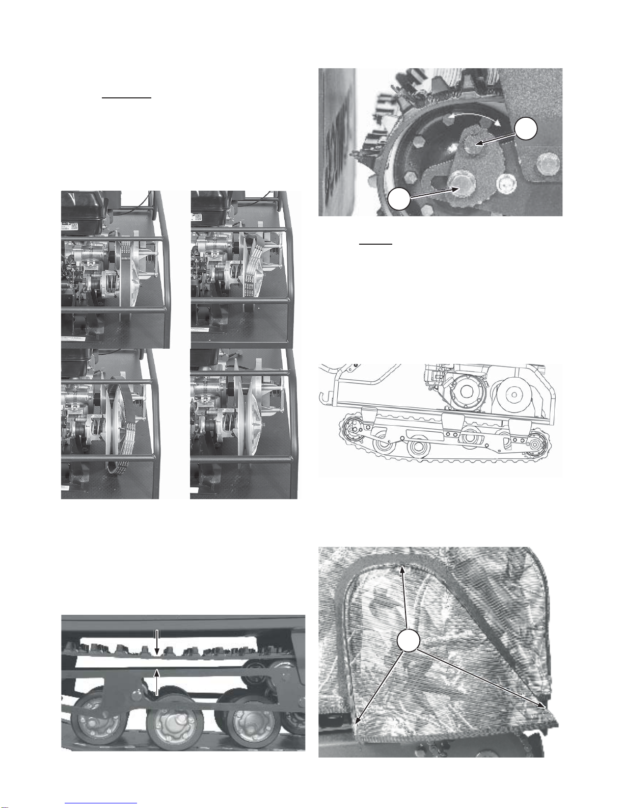
12.1 Track maintenance
Check the track condition and its tension after each trip.
Excessive track tension is often the reason for power loss and
causes engine overload.
Never operate the SNOWDOG with severe track damage.
In case of severe track damage, you should seal it to prevent
moisture from ruining the track’s cord.
The cord threads should not stick out of the track’s side.
If they do, cut them off.
Check the track’s metal brackets after each trip. If bent,
straighten. If a bracket is missing, replace it. Operating damaged
tracks leads to their rapid deterioration.
Inspect and clean the track after each trip.
When operating the SNOWDOG in the wet snow, clean the
track more often, especially before a prolonged stop. Do not
expose the track to oil and various chemicals.
Do not store the SNOWDOG under direct sunlight.
Loosen the track before storage.
We recommend storing the SNOWDOG in suspended
position. In case of a long-term storage the track must be
rotated to a new position once a month.
12.2 Transportation
Drain the fuel from the tank or shut down the fuel valve
before transporting. The SNOWDOG must be in a horizontal
position during loading and unloading. When transporting the
SNOWDOG, make sure it is secure.
SNOWDOG cannot be stacked during transportation.
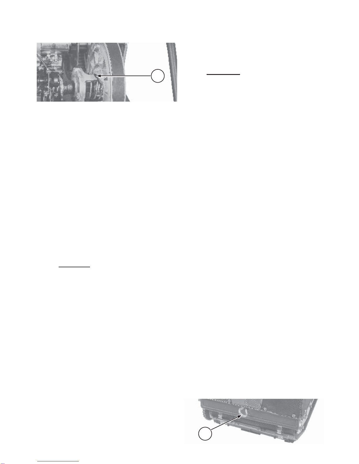
Snowdog is equipped with connector for towing eye bolt (1)
in the front part of the chassis on top part of the front mudflap.
It is designated to mount the Snowdog during transportations,
etc.
Eye bolt is provided with SNOWDOG.
1
1

10
13 Maintenance tips
13.1 Changing the oil
Change the oil in the engine in accordance with
recommendations from the engine owner`s manual.
!CAUTION
Do not touch the muffler immediately after
the engine is stopped in order to avoid getting
burned.
13.2 Replacement of CVT belt
Turn off the engine. Lock the parking brake.
To replace the CVT belt, pull the belt off
the large pulley and then from the CVT (as per
picture below). Install the belt in the reverse order.
p
p
)
)
Replace the CVT belt, if it`s worn out or its width is less
than 1.06 in (27 mm).
13.3 Checking the track tension
Before starting any movement check the condition and
tension of the track. Overtension leads to engine power loss and
causes overloads.
Place the SNOWDOG on a flat surface. Measure the
distance between the side plate chassis and the track. It should
have a value of 0.4– 0.8 in (10 – 20 mm).
13.4 Track tensioning
Loosen the screws (1) on both sides of the rear mounting
shaft. Turn eccentric (2) to adjust the tensioner axis.
Check the track tension. Tighten the bolts.
VNOTE:
If the tracksled is regularly falling to one side,
increase the tension of the track on the same
side. On the opposite side, loosen the tension
of the track.
13.5 Suspension trolleys diagnostic
The three spring trolley may turn upside-down if SNOWDOG
is driven over obstacles such as logs, rocks, etc.
In this case SNOWDOG leans forward, looses power and
speed. Do not operate SNOWDOG if this happens. Return the
three spring trolley into proper position.
13.6 Checking the chain tension
It is necessary to remove the protection cover to check the
track tension or change the sprocket or chain. To do this, remove
the three screws (1) that hold the chain cover and remove the
cover. To install the cover do same steps in the reverse order.
1
1
2

11
Correctly tensioned chain will have a loose lift of 0.2 in
(5 mm) between the sprocket.
Loose lift less than 0.2 in (5 mm) will result in rapid chain
stretching, and will lead to fast sprocket wear. An excessively
loose chain can fall off during operation. Loose chain needs to
be tightened.
While operating, the chain stretches, and the distance
between chain links changes. If the adjustment range is not
enough, the chain should be replaced. Do not shorten the chain
by removing one or more links.
When cleaning chain, check the condition of the rubber
seals between the plates. If the seals are damaged, and two tips
protrude from the chain, the chain requires urgent replacement.
13.7 Adjusting the chain tension
To adjust the chain tension:
1. Loosen six screws (1) that mount motor and CVT
brackets with SNOWDOG’s chassis platform.
2. To loosen the chain you need to move the engine
mount with the motor forward in the direction
of movement; to tension the chain you need to move
the chain tensioning engine mount with the motor
back against the direction of SNOWDOG movement.
3. Check the chain tension. Repeat step 2 if necessary.
4. Tighten six bolts (1) to the engine mounts of the
SNOWDOG chassis platform.
13.8 Reverse gearbox (if available)
13.8.1 Oil change
1. Unscrew the oil filling plug (1) of the reverse gearbox.
2. Pump out the used oil from the reverse gearbox.
3. Fill the gearbox with the new oil and screw the oil
filling plug.
YIT IS RECOMMENDED TO USE THE
ENGINE OIL FOR THE REVERSE
GEARBOX. REQUIRED AMOUNT
OF OIL IN THE GEARBOX IS 150 ML.
The oil level in the reverse gearbox can be checked with
pumping oil out and pouring a measured amount of it.
13.8.2 Adjustment of the shift cable
If the shift cable of the reverse gearbox is sag or there are
difficulties with switching gears, adjust the shift cable.
!WARNING!
Operating the SNOWDOG with insufficient
adjustment of the shift cable will cause damage to
the reverse gearbox.
1. Shut down the engine. Switch the lever of the reverse
gearbox into the “forward” position.
2. Loosen the locknut (1), tighten the adjusting screw
(2). Loosen the cable fixing nut (3).
1
1
g
p
p
p
2
1
3

12
3. Move the lever (4) all the way down. Rotating the
driven pulley of CVT, make sure the gear “forward”
is switched on.
4. Loosen the bolts (5) and move the bracket (6) down
until the moment of a significant tension of the spring.
Tighten the bolts (5).
5. Pull the shift cable and tighten the cable fixing nut
(3).
6. Create the required tension using the adjusting screw
(2) and tighten the locknut (1).
7. Switch the lever of the reverse gearbox into the
“reverse” position. Rotating the driven pulley of CVT,
make sure the gear “reverse” is switched on.
Repeat the adjustment if necessary.
13.9 Parking brake
Parking brake consists of brake caliper with pads, brake
disc, brake cable and brake lever with a lock.
13.9.1 Brake actuator. Checking, service
The brake is a combination of a steel disk on the driven
shaft of the variator, and a device that compresses the disc
brake caliper pads. The braking force is transmitted via the
brake lever cable.
The parking brake is actuated by a lever with the clamp on
the left handlebar. Check the free movement of lever A. It should
have a value of 0.2 – 0.4 in (5– 10 mm).
If the braking force on the lever is not sufficient, for
example, when brake pads are worn out, you need to adjust the
brake lever stroke.
To do this, loosen the locknut (1) and rotate the adjusting
screw (2) counterclockwise to pull cable so that the brake lever
has a free wheeling within 0.2 – 0.4 in (5–10 mm).
To loosen the brake cable, loosen the locknut (1) and
rotate the adjusting screw (2) clockwise.
If the lever adjustment is not enough to set up the free
lever motion, adjust the brake caliper and check the condition
of pads.
4
56

13
13.9.2 Brake caliper type 1. Checking and service
Caliper parts:
1. Bolts that adjust the position of the caliper (provide
parallelism of brake pads and the brake disc).
2. Fastening bolts of a caliper.
3. Brake cable fixing bolt.
4. Brake cable stop.
5. Bolt that adjust the distance between the pads.
6. Locknut of the adjusting bolt.
Adjusting the brake caliper:
Fully loosen the tension of the brake cable on the lever,
as described in paragraph 13.9.1. Ensure ease of pushing the
lever and the parking brake cable and ease of returning them to
the starting position.
1. If the movement of the lever is complicated, lubricate or
replace cable.
2. If the parking brake lever is in the starting position, and
the cable is slack — adjust the tension of the cable on the parking
brake caliper. To do this, loosen the bolt (3) and pull the cable to
remove its slackness. Do not create tension in the cable. Tighten
the bolt (3) and check the operation of the parking brake lever.
3. Turn the bolts (1) to adjust the position of the caliper
to the brake disc. The fixed brake pad should be parallel to the
brake disc. Adjust minimum possible distance between the fixed
brake pad and brake disc. The brake pad is allowed to graze on
the brake disk if it is not obstructing the disk`s rotation.
Loosen the locknut (6). Tighten the bolt (5) until the
moment of touching of the movable brake pads to the brake
disc. Holding the bolt (5), tighten the locknut (6). Check the
rotation of the brake disk. The brake pads are allowed to graze
on the brake disk if they are not obstructing the disk`s rotation.
4. Check the movement of the parking brake lever.
If necessary, adjust the tension of the cable as described in
paragraph 13.9.1.
5. Check the condition of the brake pads. Limit the working
thickness of the brake pads` material to 0,02 in (5 mm).
If the brake pads are worn, replace the brake caliper.
If the brake pads are in order adjust the brake caliper as
described in paragraph 13.9.2, subparagraph 2.
13.9.3 Brake caliper type 2. Checking and service
Fully loosen the tension of the brake cable on the lever,
as described in paragraph 13.9.1. Ensure ease of pushing the
lever and the parking brake cable and ease of returning them to
the starting position.
1. If the movement of the lever is complicated, lubricate
or replace cable.
2. Loosen the bolt (1) and pull the cable until the
necessary clearance between the brake pads and the
brake disk is set up.
3. Tighten the bolt (1) and check the movement of the
parking brake lever.
4. Loosen the nuts (2) of the brake caliper bracket and
adjust the position of the brake pads to the brake disk.
Сheck the functioning of the parking brake.
If the brake pads are
obstructing the brake disk`s rotation,
increase the brake lever stroke.
2
1

14
13.10 Adjusting the throttle
To adjust the throttle lever, loosen the locknut (2) and
rotate the adjusting screw (1) counterclockwise. Pull the rope so
that the throttle has a free running within 0,2– 0,3 in (5– 7 mm).
To loosen the throttle cable, loosen the locknut (2) and
rotate the adjusting screw (1) clockwise. Loosen the cable.
13.11 Snowdog`s general electric circuit scheme*
* for engine`s detailed electric circuit please contact Briggs&Stratton dealers
1
1
2

15

All information in this manual corresponds to the state of the products at the date of signing and printing the document. The
manufacturer reserves the right to make changes to design without prior notice and without any obligations. If a difference is found
between this Manual and your Snowdog, please contact your Snowdog dealer for the latest information. The service life of the
Snowdog, subject to the rules of operation and maintenance specified in the Manual, is 5 years.
All rights reserved. Any information contained in this manual may not be reproduced or unauthorizedly used without the prior
permission of the manufacturer — Kaliningrad Motor Factory LLC.
Kaliningrad Motor Factory LLC
Russia, Kaliningrad, Pechatnaya 56
www.snowdog.com
+7 (4012) 994-101
4986-9900-0000
This manual suits for next models
4
Table of contents
Other SNOWDOG Snowmobile manuals

SNOWDOG
SNOWDOG Sport B13R User manual

SNOWDOG
SNOWDOG Snowdog COMPACT Operating instructions

SNOWDOG
SNOWDOG Sport B13 MER User manual

SNOWDOG
SNOWDOG COMPACT B13 ME WR User manual

SNOWDOG
SNOWDOG Twin Track V14 MER User manual

SNOWDOG
SNOWDOG Sport B13 MER User manual

SNOWDOG
SNOWDOG COMPACT B7ZE L User manual

SNOWDOG
SNOWDOG Compact B10 ME User manual

SNOWDOG
SNOWDOG STANDARD B10 User manual