SnowEx Liqui Maxx 170802 Operating instructions

November 15, 2018
Lit. No. 76616, Rev. 02
Liqui Maxx™ Sprayer Systems
Owner's Manual and Installation Instructions
Original Instructions
This manual and instructions are for Liqui Maxx Sprayer Systems
with serial numbers beginning with 170802 and higher.
This document supersedes all editions with an earlier date.
CAUTION
Read this document before operating
or servicing the equipment.


Lit. No. 76616, Rev. 02 3 November 15, 2018
TABLE OF CONTENTS
PREFACE.................................................................... 4
Warranty Registration ........................................... 4
Owner's Information Form .................................... 4
SAFETY ...................................................................... 5
Safety Definitions.................................................. 5
Warning/Caution Labels ....................................... 5
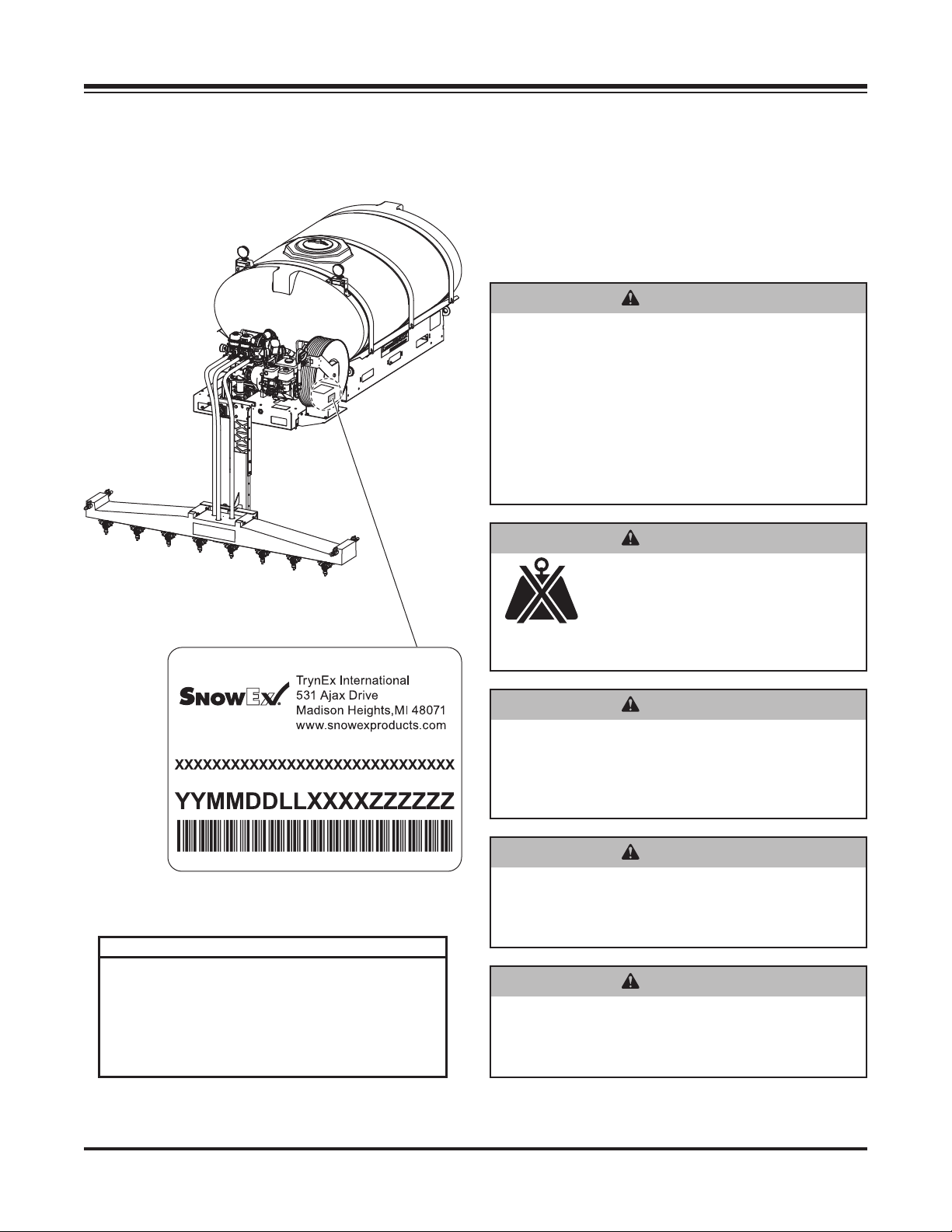
Serial Number Label ............................................. 6
Safety Precautions................................................ 6
Fuses .................................................................... 7
Personal Safety..................................................... 7
Fire and Explosion ................................................ 8
Cell Phones........................................................... 8
Ventilation ............................................................. 8
Battery Safety ....................................................... 8
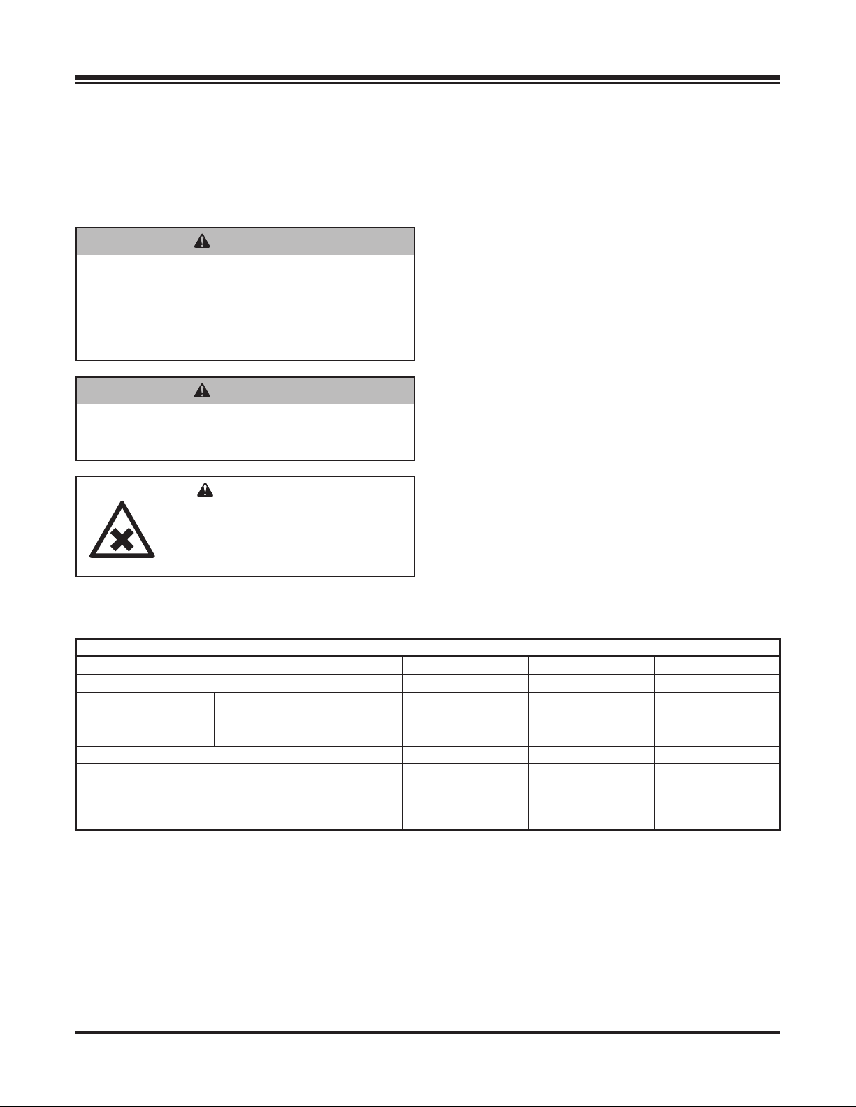
Torque Chart ......................................................... 8
LOADING.................................................................... 9
Certification........................................................... 9
Specifications........................................................ 9
INSTALLATION INSTRUCTIONS ............................ 10
Installation and Removal..................................... 10
Control Box Mounting ......................................... 12
Wiring Diagram ................................................... 13
Installation........................................................... 14
Mounting the Display Console & Switches... 14
Speed Sensor Installation ............................ 15
Standard Control Installation .............................. 15
Wiring Diagram............................................. 15
Battery Connections..................................... 15
FILLING .................................................................... 16
First Time Filling.................................................. 16
Routine Filling ..................................................... 16
Gasoline ....................................................... 16
Adding Brine................................................. 16
Oil ................................................................. 16
OPERATING & CALIBRATION INSTRUCTIONS ... 18
Control Operation ............................................... 18
Deluxe Control.............................................. 18
Standard Control .......................................... 19
Deluxe Console Functions .................................. 20
Rotary Switch Position Functions................. 20
Calibration Positions..................................... 20
Soft Key Functions ....................................... 20
Calibration........................................................... 21
Entering Calibration Values.......................... 21
"Special" Calibration ........................................... 24
Entering Calibration Values.......................... 24
Console Switches & Buttons............................... 28
Section Switches .......................................... 28
Resetting System Counters.......................... 29
Standard Sprayer Control ................................... 30
Sprayer Console........................................... 30
Spray Boom Operation .......................................30
Wing Spray Nozzle Selection....................... 30
Downward Spray Nozzle Selection .............. 31
Nozzle Alignment ......................................... 31
Default Control Settings...................................... 31
Deluxe Control.............................................. 31
Application Rates................................................ 32
Manual Mode................................................ 32
Calculations ........................................................33
Equations......................................................33
Conversions.................................................. 33
Example Calculation..................................... 34
MAINTENANCE........................................................35
Periodic Maintenance ......................................... 35
Cleaning.............................................................. 35
End of Season and Storage................................35
Nozzle Maintenance ...........................................35
Pump Maintenance ............................................. 35
TROUBLESHOOTING..............................................36
TROUBLESHOOTING – DELUXE CONTROL ........ 37
Wiring Diagram – Electric Start System ............. 38
Wiring Diagram – Hydraulic System ................... 39

Lit. No. 76616, Rev. 02 4 November 15, 2018
PREFACE
This manual has been prepared to acquaint you with
the safety information, operation, and maintenance of
your new machine. Improper installation and operation
could cause personal injury and/or equipment and
property damage. Read and understand the Owner's
Manual before installing, operating, or making
adjustments. Keep this manual accessible.
When service is necessary, call SnowEx®Technical
Service at 1-800-SALTERS (725-8377).
NOTE: This unit is designed to be used with
salt brine; the use of additives may impact
performance.
NOTE: Do not modify or alter the machine.
Altering the unit in any way will void the warranty.
The Liqui Maxx™ Sprayer System is designed to apply
brine to pre-treat, anti-ice, and post-treat parking lots
and roadways. Each Liqui Maxx unit consists of a
holding tank, pumping system and control, and a spray
boom.
OWNER'S INFORMATION
Owner's Name: ______________________________________________________________________
Date Purchased: _____________________________________________________________________
Outlet Name: ______________________________________________ Phone:_________________
Outlet Address: ______________________________________________________________________
Vehicle Model: _______________________________________________ Year: _______________
Equipment Model: ____________________________________ Serial #:______________________
Length:________________________ Weight: __________________ lb/kg: _________________
Standard Control
The standard version of the control has the ability
to turn the sprayers ON and OFF and increase or
decrease the pressure of the system from the cabin.
Deluxe Control
The deluxe version of the control unit has many
features that include: push-button controls, application
rate adjustment and selection, automatic and manual
control modes, visual and audio alarms, and a BLAST
function for spot applications.
A separate GPS unit is offered that incorporates the
vehicle speed to automatically adjust the flow rate
and maintain the desired application rate. The deluxe
control is also compatible with some vehicle speed
sensors that can replace the GPS unit. Consult your
vehicle owner's manual for more information.
WARRANTY REGISTRATION
Warranty registration is available online at
www.snowexproducts.com. Under "Support" select
"Warranty Registration" and submit the form online.

Lit. No. 76616, Rev. 02 5 November 15, 2018
SAFETY
SAFETY DEFINITIONS
NOTE: Indicates a situation or action that can lead
to damage to your sprayer and vehicle or other
property. Other useful information can also be
described.
Both Sides
WARNING
Indicates a potentially hazardous situation
that, if not avoided, could result in death or
serious personal injury.
CAUTION
Indicates a potentially hazardous situation
that, if not avoided, may result in minor or
moderate injury. It may also be used to alert
against unsafe practices.
WARNING/CAUTION LABELS
Become familiar with and inform users about the
warning and caution labels on the machine.
If labels are missing or cannot be read, call
1-800-SALTERS (725-8377).
Model TSA-300 Only

Lit. No. 76616, Rev. 02 6 November 15, 2018
SAFETY
Code Definition
YY 2-Digit Year
MM 2-Digit Month
DD 2-Digit Day
LL 2-Digit Location Code
XXXX 4-Digit Sequential Number
ZZZZZZ Model #
SAFETY PRECAUTIONS
Improper installation and operation could cause
personal injury and/or equipment and property
damage. Read and understand labels and the
Owner's Manual before installing, operating, or making
adjustments.
WARNING
• Before working with the equipment, secure all
loose-fitting clothing and unrestrained hair.
• Before operating the sprayer system, verify
that all safety guards are in place.
• Always shut vehicle OFF before attempting
to attach, detach, or service sprayer system.
• Never attempt to take a unit off a truck with
liquid in it.
• Do not climb into or ride on the machine.
WARNING
Securely bolt and strap unit into place on the
vehicle bed using the optional UMK-200 bolt
kit and ratchet straps or similar. Unit must
be strapped down and bolted into position
before operating or transporting.
WARNING
Vehicle handling and characteristics will
change with the unit installed. Avoid any
sudden steering maneuvers, starts, or stops
that could create sloshing and instability.
WARNING
Always make sure that personnel are clear
of areas of danger when using equipment.
Maintain 60' distance from all bystanders
when operating the sprayer system.
WARNING
Overloading could result in an
accident or damage. Do not exceed
GVWR or GAWR ratings as found
on the driver-side vehicle door
cornerpost. See Filling section to determine
maximum volumes of spraying material.
SERIAL NUMBER LABEL

Lit. No. 76616, Rev. 02 7 November 15, 2018
SAFETY
WARNING
Do not install the control for this product in
the deployment path of an air bag. Refer to
vehicle manufacturer's manual for air bag
deployment area(s).
WARNING
Inspect the unit periodically for defects. Parts
that are broken, missing, or worn out must be
replaced immediately. Do not alter any part of
the unit without prior written permission from
the manufacturer.
CAUTION
Brine is typically a clear to cloudy white
liquid with no odor. It may be irritating to the
eyes, skin, and respiratory system. For more
safety information on brine and other de-icing
materials, refer to the manufacturer's Safety
Data Sheet (SDS).
CAUTION
Do not leave material in the unit for long
periods of time.
CAUTION
During the sprayer system installation
we recommend the addition of an OSHA
compliant Backup Alarm. This alarm is
required for OSHA governed employers.
CAUTION
• Do not operate a sprayer system in need of
maintenance.
• Before operating the sprayer system,
reassemble any parts or hardware removed
for cleaning or adjusting.
• Before operating the sprayer system,
remove materials such as cleaning rags,
brushes, and hand tools from the unit.
• Before operating the sprayer system, read
the engine owner's manual, if so equipped.
• While operating the unit, use auxiliary warning
lights, except when prohibited by law.
• Tighten all fasteners according to the
Torque Chart. Refer to Torque Chart for the
recommended torque values.
NOTE: Lubricate grease fittings after each use.
Use a good quality multipurpose grease.
FUSES
The electrical system contains several
automotive-style fuses. If a problem should occur and
fuse replacement is necessary, the replacement fuse
must be of the same type and amperage rating as
the original. Installing a fuse with a higher rating can
damage the system and could start a fire.
PERSONAL SAFETY
• Remove ignition key and put the vehicle in PARK
or in gear to prevent others from starting the
vehicle during installation or service.
• Wear only snug-fitting clothing while working on
your vehicle or sprayer system.
• Do not wear jewelry or a necktie, and secure long
hair.
• Wear safety goggles to protect your eyes from
brine, battery acid, gasoline, dirt, and dust.
• Do not eat, drink, smoke, rub your eyes, or touch
bare skin while spraying.
• Never point spray gun at people or animals.
• Avoid touching hot surfaces such as the engine,
radiator, hoses, and exhaust pipes.
• Always have a fire extinguisher rated BC handy,
for flammable liquids and electrical fires.
CAUTION
Disconnect electric and/or hydraulic power
and tag out, if required, before servicing or
performing maintenance.
WARNING
Vehicles <10,000 lb GVWR: Obstructing the
visibility from the vehicle's rear camera could
result in serious injury or damage. An auxiliary
camera system shall be installed if the
vehicle's rear camera is removed or blocked.

Lit. No. 76616, Rev. 02 8 November 15, 2018
1/4-20 109 154
1/4-28 121 171
5/16-18 150 212
5/16-24 170 240
3/8-16 269 376
3/8-24 297 420
7/16-14 429 606
7/16-20
9/16-12
9/16-18
5/8-11
5/8-18
3/4-10
3/4-16
7/8-9
7/8-14 474 669
644 9091-8
1-12 704 995
1/2-13
1/2-20
11.9
13.7
24.6
27.3
43.6
26.9
53.3
93
148
49.4
69.8
77.9
106.4
120.0
8.4
9.7
17.4
19.2
30.8
35.0
49.4
55.2
75.3
85.0
M6 x 1.00
M12 x 1.75
M8 x 1.25
M14 x 2.00
M10 x 1.50
M27 x 3.00
M22 x 2.50
M30 x 3.50
M24 x 3.00
M20 x 2.5011.1
19.5
38.5
67
107
7.7
613
778
1139
1545
450
428
562
796
1117
M33 x 3.50
M36 x 4.00
2101
2701
1468
1952
325
M16 x 2.00 231
167
M18 x 2.50 318222
Recommended Fastener Torque Chart
Size Size
Torque (f t-lb)
Grade
5
Grade
8
Metric Fasteners Class 8.8 and 10.9
These torque values apply to fasteners
except those noted in the instructions.
Torque (f t-lb)
Grade
5
Grade
8
Size Size
Torque (f t-lb)
Class
8.8
Class
10.9
Torque (f t-lb)
Class
8.8
Class
10.9
Inch Fasteners Grade 5 and Grade 8
SAFETY
TORQUE CHART
CAUTION
Read instructions before assembling.
Fasteners should be finger tight until
instructed to tighten according to the Torque
Chart. Use standard methods and practices
when installing equipment, including proper
personal protective safety equipment.
FIRE AND EXPLOSION
Be careful when using gasoline. Do not use gasoline
to clean parts. Store only in approved containers away
from sources of heat or flame.
CELL PHONES
A driver's first responsibility is the safe operation of
the vehicle. The most important thing you can do
to prevent a crash is to avoid distractions and pay
attention to the road. Wait until it is safe to operate
Mobile Communication Equipment such as cell phones,
text messaging devices, pagers, or two-way radios.
VENTILATION
BATTERY SAFETY
WARNING
Gasoline is highly flammable and gasoline
vapor is explosive. Never smoke while
working on vehicle. Keep all open flames
away from gasoline tank and lines. Wipe up
any spilled gasoline immediately.
CAUTION
Batteries normally produce explosive gases
which can cause personal injury. Therefore,
do not allow flames, sparks, or lit tobacco
to come near the battery. When charging or
working near a battery, always cover your
face and protect your eyes, and also provide
ventilation.
• Batteries contain sulfuric acid, which burns
skin, eyes, and clothing.
• Disconnect the battery before removing or
replacing any electrical components.
WARNING
Vehicle exhaust contains lethal fumes.
Breathing these fumes, even in low
concentrations, can cause death. Never
operate a vehicle in an enclosed area without
venting exhaust to the outside.

Lit. No. 76616, Rev. 02 9 November 15, 2018
LOADING
Liqui Maxx™ Sprayer System
Tank Model TSA-300 TSA-500 TSA-750 TSA-1250
Capacity (gal) 300 500 750 1250
Tank and Pump
Dimensions (in)
Length 101 112 118 119
Width 53 59 75 85
Height 24 48 55 73
Empty Unit Weight (lb) 500 600 700 1000
Full Unit Weight (lb) 3500 5600 8200 13500
Suggested Gross Vehicle
Weight Rating (GVWR) (lb) 8,500–10,000 14,000–16,000 16,000–19,500 19,500–26,000
Vehicle Class Class 2B Class 4 Class 5 Class 6
SPECIFICATIONS
This Owner's Manual covers vehicles that have been
recommended for carrying the sprayer system. Please
see your local dealer for proper vehicle applications.
CERTIFICATION
WARNING
Overloading could result in an accident or
damage. Do not exceed GVWR or GAWR as
found on the driver-side cornerpost of vehicle.
WARNING
New untitled vehicle installation of a sprayer
system requires National Highway Traffic
Safety Administration altered vehicle
certification labeling. Installer to verify that
full sprayer does not exceed GVWR or GAWR
rating label and complies with FMVSS.
CAUTION
Read and adhere to manufacturer's
ice-control material package
labeling, including Material Safety
Data Sheet requirements.

Lit. No. 76616, Rev. 02 10 November 15, 2018
2. Connect the hose underneath the unit:
Securely fasten the 90° elbow connection to the
tank bulkhead fitting underneath the unit. Make
sure that the bulkhead fitting is securely fastened
to the tank to prevent leaks. Run the 2" hose from
the elbow to the shut-off valve below the pump.
Clock the 90° elbow so that the hose remains free
of kinks; cut it to length. Clamp the hose using
two (2) clamps on each end to prevent leaks. In
low temperatures, warming the hose may ease
installation. Dip the hose in hot water or carefully
use a heat gun for 20–40 seconds.
3. Connect the servo valve to the 1-1/2" bulkhead
fitting on the pump side of the brine tank with
supplied 1-1/2" flexible hose. Insert 1-1/2" hose
barb into bulkhead fitting with pipe dope. Tighten
securely. Cut hose to length and attach with four
provided hose clamps.
4. Lift the main tank and pump assembly using the
fork lift pockets. Use caution when inserting forks.
Improper insertion may puncture or damage the
brine tank and tubing routed underneath the unit.
Center the tank and pumping system from driver's
side to passenger's side on top of the truck bed
and lower into position.
INSTALLATION AND REMOVAL
NOTE: To prevent leaks, use a thread-sealing
compound on all threaded connections. Do
not use Teflon®tape, as fragments will clog the
spray nozzles. Clamped connections may require
periodic retightening.
1. Bolt the pump and tank platforms together
(six places).
INSTALLATION INSTRUCTIONS
Teflon®is a registered trademark of E. I. du Pont de Nemours and Company.
WARNING
Always shut vehicle OFF before attempting to
attach, detach, or service sprayer system.
WARNING
Never attempt to take a unit off a truck with
liquid in it.
Shut-Off Valve
90° Elbow
WARNING
Overloading could result in an
accident or damage. Do not exceed
GVWR or GAWR ratings as found
on the driver-side vehicle door
cornerpost. See Specifications to determine
maximum volumes of spraying material.
WARNING
New untitled vehicle installation of a sprayer
system requires National Highway Traffic
Safety Administration altered vehicle
certification labeling. Installer to verify that
full sprayer does not exceed GVWR or GAWR
rating label and complies with FMVSS.

Lit. No. 76616, Rev. 02 11 November 15, 2018
Wood Spacer
INSTALLATION INSTRUCTIONS
5. Install any optional kits and equipment. To install the
BRM-175 Adjustable Boom Receiver Mount, unfasten
the rear brake light, install the kit, and re-install the
light on the top rear face of the BRM bracket.
6. Securely bolt and strap unit into place on the
vehicle bed using the optional UMK-200 Universal
Mounting Kit or similar brackets and ratchet straps.
Hardware attaching the sprayer system directly to
the vehicle is the responsibility of the end user.
NOTE: Pay special attention when drilling or
clamping dissimilar metals to aluminum bodies.
Galvanic corrosion can occur if not handled
properly. Contact vehicle manufacturer for
recommended attachment practices.
7. Measure the distance between the front of the
truck bed and the tank base. Make a spacer to fill
area between the tank base and the front of the
truck bed. Failure to install this spacer could result
in damage to the sprayer and/or vehicle.
8. Install the boom so that the nozzles measure
18"–22" from ground to nozzle tip. This is to
prevent damage and ensure optimal performance.
Consider using the optional BRM-175 Adjustable
Boom Receiver Mount if the tips of the nozzles lie
outside this zone when using your stock receiver
hitch.
9. Connect the boom to the pump. Clamp the quick
disconnect attachments on the boom hoses to the
manifold valves on the pumping unit. Route the
hoses to the installed boom with adequate slack
and cut the hoses to fit. Clamp the hose tightly to
the boom to prevent leaks.
CAUTION
Ensure that nozzles have minimum 18 inches
ground clearance. Low boom heights can
cause accidental breakage from curbs,
uneven surfaces, and other obstacles.
Adjustment may require optional BRM-175
Adjustable Boom Mount.
18"–22"
2 3
1
1
2
3

Lit. No. 76616, Rev. 02 12 November 15, 2018
3. Connect the harness to the back of the control
(PN 72145) and mount the control in a suitable
location within easy reach of the vehicle operator
without restricting access to the vehicle controls
and instruments.
4. Connect the harness to the battery. Refer to the
wiring diagrams for battery connections.
INSTALLATION INSTRUCTIONS
CONTROL BOX MOUNTING
NOTE: Use dielectric grease to prevent corrosion
on all connections.
Before beginning the installation, remove all battery
cables from the vehicle battery terminals.
1. Route the vehicle harness (PN 72141) along the
vehicle frame. Do not route it close to the exhaust
system or engine, where extreme heat could melt
the wiring insulation and short out the sprayer and
vehicle electrical systems. Attach the harness to
frame holes and frame supports. Do not attach
to fuel or brake lines. Use heavy-duty cable ties
or frame clamps to fasten the harness along the
frame.
2. Route the control harness (PN 72143) using
an existing access hole through the fire wall
into the vehicle cab. If adding an access hole is
necessary, check the area on the other side of
the fire wall to make sure that you will not drill
into vehicle wiring or other components. Attach
securely with cable ties.
CAUTION
Before drilling holes, check to see that no
vehicle wiring or other components could be
damaged.
WARNING
Do not install the control for this product in
the deployment path of an air bag. Refer to
vehicle manufacturer's manual for air bag
deployment area(s).
CAUTION
Do not mount the control close to any heater
vents or in areas prohibited by the vehicle
manufacturer for crashworthiness. See
the vehicle's body builder's book, owner's
manual, or service manual for details.
CAUTION
Do not alter, modify, or install component in
shaded areas shown below. Failure to comply
may interfere with air bag deployment or
cause injury to operator in an accident.

Lit. No. 76616, Rev. 02 13 November 15, 2018
ACC1
ACC2
ACC PWR
ACC PWR
CHMSL
CHOKE SW
BOARD
ON/OFF SW
BOARD
CAB CONTROL
SPEED CONN (NC)
VSE/GND
TANK CONN
SWITCHED VSE
HOLD CONN
PN 72145
PN 72141
VEHICLE BATTERY
POSITIVE (+)(–) NEGATIVE
PN 72143
FUSE
10A
FUSE
50A
PN 72155
REAR OF
VEHICLE
CHMSL CONN
ACC1 CONN
ACC2 CONN
SECTION 3 CONN
SECTION 2 CONN
SECTION 1 CONN
CONTROL CONN
FLOW CONN
CONTROL CONN
FLOW CONN
SECTION 3 CONN
SECTION 2 CONN
SECTION 1 CONN
ACC1 CONN
ACC2 CONN
CHMSL CONN
PN 72155
RELAY CONN
LEVEL SW CONN
FLOW SOLENOID CONN
PN 72153
PN 72151
FLOW SOLENOID CONN
CHOKE MOTOR CONN
FUSE
3A
CHOKE LAMP SW CONN
SECTION 1
SECTION 2
SECTION 3
INSTALLATION INSTRUCTIONS
WIRING DIAGRAM

Lit. No. 76616, Rev. 02 14 November 15, 2018
INSTALLATION
Mounting the Display Console & Switches
Select a mounting location that is convenient to reach
and highly visible to the operator. Do not install in a
position that obstructs the view of the road or work
area. Whenever possible, avoid locations that expose
the console to direct sunlight, high temperature,
strong chemicals, or rain.
Place the mounting bracket in desired location and
secure with the self-tapping screws provided.
Self-Tapping
Screws
Mounting
Bracket
INSTALLATION INSTRUCTIONS

Lit. No. 76616, Rev. 02 15 November 15, 2018
INSTALLATION (CONT.)
Speed Sensor Installation
Installation Note: The harness provides local
connection for the speed sensor. For speed sensor
installations on implements, add 3-pin extension
cables as required.
Please Note: If you have purchased an Astro GPS
Speed Sensor, a Vansco radar, or other radar or GPS
speed sensor, install the Astro, the Vansco, or other
radar as described in the instructions included with the
unit.
Speed Sensor Options
In addition to the standard Hall-effect magnetic speed
sensor, the deluxe control may be interfaced with a
variety of other speed sensing equipment. Several
options are listed below.
Astro Series or Other GPS Speed Sensor
Interfaces
The deluxe control may also be used with most GPS
speed sensors that output a pulsed signal, such as
the Micro-Trak Astro 5, SkyTrak, or Dickey-John GPS
speed sensors. An adapter cable may be required.
Installing External BLAST Switch
An optional external Momentary ON BLAST switch
can be connected to the two quick-connect terminals
provided on the harness (see Wiring Diagram). The
remote BLAST switch allows the operator to control
the BLAST function from a switch mounted on an
armrest or other convenient location.
STANDARD CONTROL INSTALLATION
Wiring Diagram
Battery Connections
IMPORTANT: Attach the red wire to the
NEGATIVE (–) post. The electrical system must
be 12V. If the tractor has two 6V batteries, the red
wire must be attached to the POSITIVE (+) post on
the battery that has the power cable to the tractor
electrical system. The brown wire can be attached
to the NEGATIVE (–) post on the other battery
or anywhere on the tractor frame. See wiring
diagram.
INSTALLATION INSTRUCTIONS
GPS Speed Sensor

Lit. No. 76616, Rev. 02 16 November 15, 2018
ROUTINE FILLING
Gasoline
Fill the motor with gasoline as needed.
Adding Brine
Fill the brine tank to the desired level using the steps
below. Use the markings on the tank for volume
reference. If filling is slow, check the intake filter.
For more information see the Maintenance and
Troubleshooting sections of this manual.
Oil
The engine is shipped without oil in the crank case.
Fill with oil prior to use in accordance with the
enclosed Honda®service manual.
Before starting the engine, be sure that the oil level is
within the limits on the dipstick. See the Honda service
manual for correct oil types and SAE viscosity
grades. The oil level should be checked before each
use.
FILLING
Refer to the Specifications section to determine
sprayer weights and capacities.
FIRST TIME FILLING
1. Install the sprayer system and any optional
equipment. See the Installation Instructions
section of this manual for details.
2. Install or attach any other equipment that will be
on the vehicle while the sprayer system will be in
use (step bumper, trailer hitch, snowplows, etc.)
and fill gas tanks.
3. Obtain the Gross Vehicle Weight Rating (GVWR),
Front Gross Axle Weight Rating (FGAWR), and
Rear Gross Axle Weight Rating (RGAWR) from
the certification label typically located inside the
driver-side door.
4. With the occupants in the truck for normal sprayer
operation, weigh the vehicle to obtain gross
vehicle weight (GVW).
5. Subtract the GVW from the GVWR to determine
the available material payload. For reference,
brine weighs approximately 10 lb/gal. For more
weight information see the Specifications section
of this manual or the material manufacturer's
specifications.
WARNING
Always shut vehicle OFF before attempting to
attach, detach, or service sprayer system.
Shut-Off Valve
Brine Fill Valve
Filter
WARNING
Overloading could result in an accident or
damage. Do not exceed GVWR or GAWR as
found on the driver-side cornerpost of vehicle.
Honda®is a registered trademark of Honda Motor Co.

Lit. No. 76616, Rev. 02 17 November 15, 2018
FILLING
Filling with an external pump
1. Connect fill hose to the brine fill valve. (Opening
the valves first will cause standing brine in the
tank to flow out.)
2. Once hose is hooked up, open the brine fill and
shut-off valves.
3. Once the valves are open, begin pumping brine
from the holding tank using the external pump.
4. Fill to the desired level.
5. Close the brine fill valve. The shut-off valve must
be open for spraying.
NOTE: After first time filling, remove the top port
from the pump and wait for a good stream before
replacing. This will remove any air blockages.
Filling with the Liqui Maxx™ sprayer pump
NOTE: This method only works when the brine
reservoir level is above the tank level. The pump
requires a gravity-fed start to remove standing
air in the piping. Once the pump is primed it will
function normally.
1. Connect fill hose to the brine intake valve.
Opening the valve first will cause standing brine in
the mixing tank to flow out.
2. Once the hose is hooked up, open the brine fill,
and close the shut-off valve.
3. Make sure that the servo valve is fully open.
a. HFS-100-2 (Manual Control): Decrease
pressure to minimum with pressure toggle
switch.
b. HFD-200EX or HFD-200HYD (Auto Control):
Control should be in "HOLD" function.
4. Once brine begins to flow in, start the motor.
5. Fill tank to desired level.
6. Close the brine fill and open the shut-off valve.
Priming
Port

Lit. No. 76616, Rev. 02 18 November 15, 2018
OPERATING AND CALIBRATION INSTRUCTIONS
CONTROL OPERATION
Deluxe Control
Follow the steps below to get started using your
deluxe control. Complete details and instructions
follow in this section.
1. Before spraying, consider what speed range
you wish to operate in and select and install the
appropriate nozzles using the application rate
charts in this manual. Note that the unit will not
function as intended outside these ranges.
2. Turn the power switch ON. The unit will display the
software version and the total hours of operation
for 1.5 seconds each. Be sure that the control is
set to HOLD or the boom switches are set to OFF
before starting the Liqui Maxx™ sprayer's motor to
prevent unintentional spraying.
WARNING
Always make sure that personnel are clear
of areas of danger when using equipment.
Maintain 60' distance from all bystanders
when operating the sprayer system.
WARNING
Vehicle handling and characteristics will
change with the unit installed. Avoid any
sudden steering maneuvers, starts, or stops
that could create sloshing and instability.
WARNING
Before operating the sprayer, verify that all
safety guards are in place.
WARNING
Unit must be strapped down and locked into
position before operating or transporting.
CAUTION
Starting the motor with no antifreeze
will damage the seal in the pump. Check
antifreeze levels before starting.
The RUN/HOLD button is the master switch
to turn all sections ON and OFF. For example,
instead of using the individual section switches,
simply use the RUN/HOLD switch.
3. Set the valves to the spray configuration. Start the
Liqui Maxx sprayer's motor by turning the motor
ON, setting the appropriate choke, and pulling the
recoil start handle.
Spray configuration:
• Brine Fill Valve: Closed
• Shut-Off Valve: Open
4. Select the spray mode by pressing the
AUTO/MAN button on the bottom left of the
control until the desired mode is displayed on the
top right of the control display. Select Automatic
Mode if you wish to have the control automatically
hold a target application rate and your unit has
a compatible speed sensor installed. If you are
doing driveways or other applications where it
is difficult to stay within a target speed range,
it may be desirable to use Manual Mode. If
speeds of 4–6 mph are desired, Manual Mode is
recommended.
Automatic Mode
1. During normal operation, set the rotary switch to
RATE to see the actual application rate per acre.
The unit will automatically adjust to the target
application rate which can be seen and adjusted
using the Up (+) and Down (–) arrow buttons on
the control. Use the RUN/HOLD button and the
boom switches to control the boom as desired.
The factory defaults below can be adjusted as
desired. See "Entering Calibration Values" in this
section.
Factory Defaults:
• Target Application Rate: 30
• Rate Increment: ± 5
• Units: gal/acre
The Automatic Mode has a BLAST function
intended for spot application that requires a higher
application rate like bridges or intersections.
This can be changed to any value and it is not
associated with the standard application rate. See
"Entering Calibration Values" in this section.

Lit. No. 76616, Rev. 02 19 November 15, 2018
OPERATING AND CALIBRATION INSTRUCTIONS
Factory Defaults:
• BLAST Target Rate: 35
• BLAST Duration: 5 seconds
• Units: gal/acre
The control is also equipped with visual and
audio alarms. The alarms will trigger if the actual
application rate is above or below 10% of the
target rate. For more information on the alarms and
other control features see "Deluxe Console" in this
section.
2. To avoid draining the vehicle battery, turn the
control OFF when not in use.
3. When finished turn the motor OFF.
NOTE: The unit cannot automatically adjust the
application rate unless there is a compatible
speed sensor installed.
Manual Mode
NOTE: In this mode the control will not
compensate for speed.
1. During normal operation, set the rotary switch to
VOLUME/MINUTE to see the flow rate. This value
can adjusted using the Up (+) and Down (–) arrow
buttons on the control. Use the RUN/HOLD button
and the boom switches to control the boom as
desired.
Factory Defaults
• Units: gal/acre
2. To avoid draining the vehicle battery, turn the
control OFF when not in use.
3. When finished turn the motor OFF.
Standard Control
Follow the steps below to get started using your
standard control. See the Owner's Operating Manual
for the control for complete details and instructions.
1. Before spraying, consider what speed range
you wish to operate in, and select and install the
appropriate nozzles using the application rate
charts in this manual. Note that the unit will not
function as intended outside these ranges.
2. Set the master switch to OFF and turn the power
switch ON.
3. Set the valves to the spray configuration. Start the
Liqui Maxx™ sprayer's motor by turning the motor
ON, setting the appropriate choke, and pulling the
recoil start handle.
Spray Configuration:
• Brine Fill Valve: Closed
• Shut-Off Valve: Open
• Return Valve: Set pressure to 40 psi by
opening and adjusting return valve.
4. During normal operation, use the master switch
and boom switches to control the boom as
desired. Increase or decrease the pressure of the
system as desired using the pressure switch.
5. To avoid draining the vehicle battery, turn OFF the
control when not in use.
6. When finished turn the motor OFF.

Lit. No. 76616, Rev. 02 20 November 15, 2018
VOLUME/MINUTE: Displays total gallons
(liters) of liquid applied per minute.
WIDTH CAL: Enter the working width.
SPEED CAL: Enter the speed calibration number in
inches (cm) per pulse.
MODE SELECT: Allows the user to change the MODE
SELECT between modes of operation: Lane, Ag, Dust,
and Turf.
TEST SPEED: Simulates ground speed for system
checkout.
RATE: Displays application rate.
FLOW CAL: Enter the calibration value assigned to your
flowmeter (see flowmeter tag).
MIN FLOW: Enter the minimum flow rate of the
application system.
ADJUST RATE: Enter an amount of change for
on-the-go adjustments to the target rate.
TARGET RATE: Enter the target application rate.
Calibration Positions Calibration Positions
Rotary Switch Position Functions
KEYLOCK FUNCTION: When locked allows the user to
view calibration values but prevents changes; allows Data
Set 1 to be cleared but prevents clearing Data Sets 2 & 3
(Volume, Area, Distance, Average & Highest Velocity).
TANK ALARM: Can be initiated by either the optional
Tank Level Switch or the Tank Counter (if Tank Alarm is
set in "Special" Calibration).
VOLUME (1) (2) (3): Displays total
gallons (liters) of liquid applied.
May be reset. SEE NOTE.
AREA (1) (2) (3): Keeps a running
count of the total area worked. May
be reset. SEE NOTE.
DISTANCE (1) (2) (3): Displays dis-
tance traveled. May be reset. SEE
NOTE.
MODE: Displays selected mode.
User selects between Lane, Ag,
Dust, and Turf Modes of operation.
Allows Audible Alarm to be RESET
by pressing the RESET button.
SPEED (1) (2) (3): Displays ground
speed in miles per hour (kilometers
per hour) or Average & Highest
velocity. May be reset. SEE NOTE.
TANK LEVEL: Displays gallons (liters)
of liquid remaining. If a FILL TANK
SIZE has been set to a value in
Calibration, pressing the "+" will make
the Tank value jump to FILL TANK
SIZE value. The value can be
decreased but not increased above the
FILL size. If the FILL TANK SIZE is set
to Zero, Tank level can be adjusted to
any value from 0 to 65,535 using the
"+" or "−"(RESET) keys.
NOTE: VOLUME, AREA, DISTANCE & SPEED counters
work in sets. If the VOLUME counter 1 is reset, it also
resets AREA counter 1, DISTANCE counter 1, and
Average & Highest Speed counter 1. This will be the
same for resetting any counters in the set.
DELUXE CONSOLE FUNCTIONS
The deluxe control features a large, easy-to-read liquid crystal display, rotary dial, and lighted panel for night use.
REMOTE BLAST SWITCH – Optional: The Optional
Remote BLAST Switch can initiate the BLAST sequence in
normal operation, the same as the console BLAST switch.
AUDIBLE ALARM: Alarm will sound for Rate errors over
10%, Tank Level below set point or Tank Empty (from Float
input). The alarm can be temporarily shut OFF by setting rotary
switch to MODE (Alarm Reset) and pressing RESET button.
NOTE: Setting ALARM ENABLE to OFF in "Special"
Calibration will disable All Audible Alarms.
WARNING LIGHT: Indicates over- or under-
application of plus or minus 10% from the Target Rate
or if the tank is low or minimum flow active. Also lit
when in CAL and Unlocked.
Multi-Function Key:
• Used to enter and exit the calibration and
"special" calibration modes.
• Used to initiate BLAST sequence in normal operations.
• Overrides flowmeter input in case of an Emergency Stop.
• Toggles between SPEED CAL and Distance traveled while
fine tuning the SPEED CAL factor or between FLOW CAL
and Volume when fine tuning the Flow Cal factor.
Soft Key Functions
BLAST
Key that changes operation from automatic control
to manual. (If Manual Control is enabled, see
page 27.)
AUTO
MAN
PROGRAM KEYS: In normal operating
modes, used to increase/decrease
application rate. With Rotary Switch
in the SPEED position, RESET key
is used to display Average and Maximum Speed. In
Volume, Area, Distance, or Speed, the "+" key selects
counter set.
• RESET: When in HOLD and not in CAL, clears the
selected counter set when held for two seconds. When
rotary switch is in the MODE position, Resets Audible
Alarm.
•When in CAL, the "+" key increases and the "−"
decreases the calibration value displayed.
RESET
OPERATING AND CALIBRATION INSTRUCTIONS
Table of contents
Other SnowEx Paint Sprayer manuals
Popular Paint Sprayer manuals by other brands

Titan
Titan ProFinish AS1130 owner's manual

Nordson
Nordson Iso-Flo instruction sheet

Graco
Graco HYDRA-SPRAY EH 333 226-333 Instructions-parts list

Graco
Graco HYDRA-SPRAY KING Instructions-parts list

Nordson
Nordson Encore LT Automatic Customer product manual

BENDEL
BENDEL Z-014S Tornador BASIC Original instruction manual