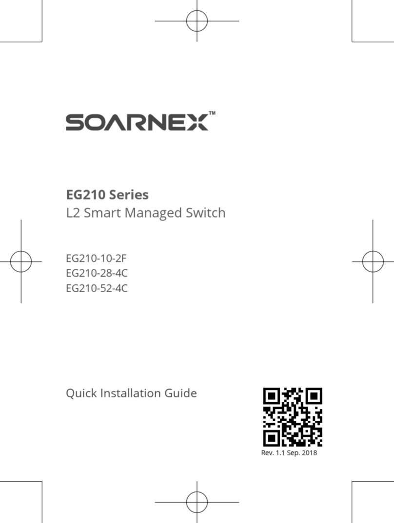
SOARNEX EG210 Series User manual

EG210 series
L2+ Smart
Management
Switch user
manual
Release 1.00.003

EG210 Series L2+ Smart Managed Switch
User Manual
1
Content
Change History ...................................................................................................................................................3
Chapter 1. Intended readers........................................................................................................................4
Chapter 2. Declaration.................................................................................................................................4
Chapter 3. Introduction ...............................................................................................................................5
Chapter 4. Overview ....................................................................................................................................5
1. Power over Ethernet (PoE).................................................................................................................6
2. Advance PoE management function..................................................................................................6
3. Excellent manageability .....................................................................................................................6
4. Management......................................................................................................................................7
1-1. Configuration the management Switch .............................................................................7
Chapter 5. Main Features ..........................................................................................................................11
1. Switch Info........................................................................................................................................11
1-1. Switch Info........................................................................................................................11
2. System..............................................................................................................................................13
2-1. System Management .......................................................................................................13
2-2. L3 Feature ........................................................................................................................14
2-3. DNS...................................................................................................................................25
2-4. IP Access List ....................................................................................................................26
2-5. Administration .................................................................................................................28
2-6. Timeout............................................................................................................................29
2-7. System Time .....................................................................................................................30
2-8. SSL ....................................................................................................................................33
2-9. SSH ...................................................................................................................................33
2-10. Telnet................................................................................................................................34
2-11. DHCP Auto Configuration.................................................................................................34
2-12. System Log .......................................................................................................................35
2-13. SNMP................................................................................................................................37
2-14. RMON...............................................................................................................................45
2-15. Statistics ...........................................................................................................................53
2-16. IEEE 802.3az EEE ..............................................................................................................55
3. Network ...........................................................................................................................................56
3-1. Physical Interface .............................................................................................................56
3-2. Spanning Tree...................................................................................................................61
3-3. Trunk ................................................................................................................................71
3-4. Mirroring ..........................................................................................................................75
3-5. Loopback Detection .........................................................................................................76
3-6. Static Unicast....................................................................................................................77
3-7. Static Multicast.................................................................................................................78

EG210 Series L2+ Smart Managed Switch
User Manual
2
3-8. IGMP Snooping ................................................................................................................79
3-9. MLD ..................................................................................................................................82
3-10. Multicast VLAN.................................................................................................................86
3-11. Multicast Filter .................................................................................................................91
3-12. Bandwidth Control ...........................................................................................................92
3-13. VLAN.................................................................................................................................94
3-14. GVRP...............................................................................................................................101
3-15. Voice VLAN.....................................................................................................................103
3-16. LLDP................................................................................................................................107
3-17. MAC VLAN......................................................................................................................124
3-18. Protocol VLAN ................................................................................................................126
4. QoS.................................................................................................................................................128
4-1. CoS .................................................................................................................................128
4-2. Port Priority....................................................................................................................129
4-3. DSCP ...............................................................................................................................130
4-4. Scheduling Algorithm Settings .......................................................................................131
4-5. IPv6 Traffic Class.............................................................................................................131
5. PoE .................................................................................................................................................132
5-1. Power over Ethernet ......................................................................................................133
5-2. Time Range.....................................................................................................................136
6. Security ..........................................................................................................................................137
6-1. Port Access Control ........................................................................................................137
6-2. Dial-In User.....................................................................................................................142
6-3. RADIUS ...........................................................................................................................144
6-4. TACACS+ .........................................................................................................................146
6-5. Destination MAC Filter...................................................................................................148
6-6. Denial of Service ............................................................................................................149
6-7. DHCP Snooping ..............................................................................................................151
6-8. Dynamic ARP Inspection ................................................................................................156
6-9. ACL .................................................................................................................................164
7. Tools ...............................................................................................................................................183
7-1. Firmware Upgrade .........................................................................................................183
7-2. Configuration .................................................................................................................185
7-3. Diagnostics .....................................................................................................................187
7-4. Reboot............................................................................................................................191
7-5. Ping.................................................................................................................................191
Chapter 6. Figures....................................................................................................................................194
Chapter 7. Events.....................................................................................................................................199
Chapter 8. Command Line Interface (CLI)................................................................................................202

EG210 Series L2+ Smart Managed Switch
User Manual
3
8.1. CLI - Symbol Description ........................................................................................................202
8.2. CLI - Base ................................................................................................................................202
8.3. CLI - Config .............................................................................................................................203
8.4. CLI - Download/Upgrade Firmware .......................................................................................203
8.5. CLI - Download/Upgrade Config ............................................................................................203
8.6. CLI - Ping.................................................................................................................................204
8.7. CLI - Save, Reboot, Reset Config ............................................................................................204
8.8. CLI - Show...............................................................................................................................204
Change History
v1.00.001: Initial commercial released (2018/03/01)
Base on FW version: v1.00.005
v1.00.002: Base on FW version: v2.10.001
Added Features:
1. Dual Image
2. Dual Configuration
3. TC Root/Protect
4. MAC-Based VLAN
5. Protocol-Based VLAN
6. Multicast VLAN Registration (MVR)
7. LLDP-MED
8. MLD
9. Dynamic ARP Inspection
10. Block unknown multicast with GUI (Multicast Filter)
11. IGMP Fast leave
12. Telnet
13. SSH
14. IP MAC Port Binding
15. Support Command Line Interface (CLI)
v1.00.003: Base on FW version: v2.10.004
Added describes of the EG210-10-2F in L2+ Smart Managed Switch.
Added describes of the command-line interface (CLI).

EG210 Series L2+ Smart Managed Switch
User Manual
4
Chapter 1. Intended readers
The document is written for networking managers who are familiar with IT concepts.
This document also provides detailed information for how to use the managed Switch via Web-Based
management interface to configure and maintain the Switches.
Chapter 2. Declaration
This document is a reference for network manager administrator to configure managed Switches. The
contents in the manual, such as web page snapshot and configuration scenarios are based on the Switch
conditions in the lab environment. This manual provides few instructions for general scenarios. But, do not
cover all usage scenarios for all users environment; the network manager administrator should configure
his devices according to actual situations.

EG210 Series L2+ Smart Managed Switch
User Manual
5
Chapter 3. Introduction
First, thank you for purchasing EG210 Series L2+ Smart Managed Switch.
This user manual is written to guideline for the models shown as follows:
L2+ Smart Managed PoE Switch
EG210-10-75W
8-Ports Gigabit 802.3at + 2*1000Base-T SFP ports (75Watts) Managed PoE Switch
EG210-10-123W
8-Ports Gigabit 802.3at + 2*1000Base-T SFP ports (123Watts) Managed PoE Switch
EG210-20-185W
16-Ports Gigabit 802.3at + 4*Combo 1000Base-T RJ-45/SFP ports (185Watts)
Managed PoE Switch
EG210-28-185W
24-Ports Gigabit 802.3at + 4*Combo 1000Base-T RJ-45/SFP ports (185Watts)
Managed PoE Switch
EG210-28-370W
24-Ports Gigabit 802.3at + 4*Combo 1000Base-T RJ-45/SFP ports (370Watts)
Managed PoE Switch
EG210-52-370W
48-Ports Gigabit 802.3at + 4*Combo 1000Base-T RJ-45/SFP ports (370Watts)
Managed PoE Switch
EG210-52-740W
48-Ports Gigabit 802.3at + 4*Combo 1000Base-T RJ-45/SFP ports (740Watts)
Managed PoE Switch
L2+ Smart Managed Switch
EG210-10-2F
8-Ports Gigabit + 2*1000Base-T SFP ports Managed Switch
EG210-28-4C
24-Ports Gigabit + 4*Combo 1000Base-T RJ-45/SFP ports Managed Switch
EG210-52-4C
48-Ports Gigabit + 4*Combo 1000Base-T RJ-45/SFP ports Managed Switch
Chapter 4. Overview
The EG210 L2+ Smart Managed PoE+ Switch to fulfill the needs of higher power requirement of PoE
network applications with Gigabit speed transmission, the EG210 L2+ Smart Managed PoE Switch is
specifically designed to meet the surveillance environment that requirements IR, PTZ, Speed Dome
cameras. With the increasing number of wired and wireless network device.
The EG210-10-2F, EG210-28-4C and EG210-52-4C provide a cost-effective solution to connect network port
that user needs in the network environment, it supports both IPv4 and IPv6 protocols. The EG210-10-2F
provides 8* Gigabit ports + 2*1000Base-T SFP ports, the EG210-28-4C provides 24* Gigabit ports +
4*Combo 1000Base-T RJ-45/SFP ports and EG210-52-4C provides 48 * Gigabit SFP Ports and 4*Combo
1000Base-T RJ-45/SFP port.

EG210 Series L2+ Smart Managed Switch
User Manual
6
1. Power over Ethernet (PoE)
The EG210 L2+ Smart Managed PoE Switch:
EG210-10-75W, EG210-10-123W
EG210-20-185W
EG210-28-185W, EG210-28-370W
EG210-52-370W, EG210-52-740W
The PoE Switch supports IEEE802.3at (PoE+) and Power Sourcing Equipment (PSE) PoE power output up to
30W/per-port.
Here are the PoE power budgets for each model:
75W for EG210-10-75W
123W for EG210-10-123W
185W for EG210-20-185W
185W for EG210-28-185W
370W for EG210-28-370W
370W for EG210-52-370W
740W for EG210-52-740W
2. Advance PoE management function
The EG210-10-75W, EG210-10-123W, EG210-20-185W, EG210-28-185W, EG210-28-370W, EG210-52-370W,
EG210-52-740W supports PoE power budget control, PoE function enable/disable, PoE power feeding
priority, PoE power limitation, and PoE schedule.
3. Excellent manageability
The Switch provides variety of management ports, such as Web network management, SNMP V1/V2c/V3,
private MIB and S-View managed utility, Switch management also can use SSL enhances security.

EG210 Series L2+ Smart Managed Switch
User Manual
7
4. Management
1-1. Configuration the management Switch
(1) Web browser / SNMP
(2) Network assistant utility (S-View)
The management Switch can be configured through the web browser, the management utility and
SNMP/MIB browser utility.
Figure 4-1-0 Default IP address and Password / Figure 4-1-1 Basic Application for managed the switch
(1) Configure the management Switch via web browser
The administrator can visually manage and maintain the Switch through the web-based configuration
interface.
Note: Please make sure the computer MUST be set on the same IP Subnet (the same as the IP Address of
Switch)
For example, the default IP Address of Switch is 192.168.1.1 with subnet mask 255.255.255.0, then the
computer should be set 192.168.1.x (where x is a number between 1 ~ 254, except 1) with subnet mask
255.255.255.0.
Open web browser and enter IP Address http://192.168.1.1 (the default IP Address of Switch) to access the
WEB platform. Default User Name and Password of the Switch are “admin”.
Figure 4-1-2 Logging onto the Web Manager
After user has logged in to the Switch for the first time, we highly suggest user to follow up the instruction
step by step listed as follows to change default admin password setting for security reason.

EG210 Series L2+ Smart Managed Switch
User Manual
8
(1)-1 On the left hand side of the web screen, Select System -> Administration
Figure 4-1-3 System -> Administration page
(1)-2 Click Modify button to change default password for the “admin”account.
Figure 4-1-4 modify account’s password.
(1)-3 On the left hand side of the web screen, select Tools -> Configuration then choice Save page, Click
“Save Settings to Flash”button to save the configuration from the RAM to FLASH.
Figure 4-1-5 save Settings to Flash

EG210 Series L2+ Smart Managed Switch
User Manual
9
(2) Configure the management Switch via management utility “S-View”
The administrator can visually manage and maintain the Switch through management utility “S-View”.
S-View allows user to discover multiple management Switches in the same L2 network via user's local PC.
With this management utility, user do not need to change the IP Address of the PC and management
Switch with the same L2 network segment, management Switch have displayed on the screen for instant
access. It allows user to configure basic configurations such as a password changed or firmware upgraded.
(3) Configure the management Switch via SNMP
By default, Switch SNMP Agent is enabled (SNMPv1).If the SNMP Community Name is “Private” which is for
READ and WRITES policy. And if the SNMP Community Name is “public” which supports READ ONLY policy.
The administrator can use SNMP community utility to READ and WRITES the parameters.
Figure 4-1-6 Default SNMP community Name
Note: SOARNEX MIB id is 45641, the Administrator could import SOARNEX private MIB file to the SNMP
management utility, and then to READ and WRITES the parameters on the Switch.
Figure 4-1-7 SOARNEX private MIB OID: 1.3.6.1.4.1.45641
Full path: iso(1).org(3).dod(6).internet(1).private(4).enterprises(1).soarnex(45641)

EG210 Series L2+ Smart Managed Switch
User Manual
10
For example, the administrator use SNMP management utility to READ and WRITES the Switch parameters.
Figure 4-1-8 example of the SNMP management utility

EG210 Series L2+ Smart Managed Switch
User Manual
11
Chapter 5. Main Features
1. Switch Info
1-1. Switch Info
The general System, Hardware, Administration, System MAC Address, IPv4, IPv6, and Automatic Network
Features information of the Switch shown as the following could be easily found on the Switch Info page.
Figure 5-1-1 Switch Information page

EG210 Series L2+ Smart Managed Switch
User Manual
12
Switch Information
System Up For
Display the duration that the Switch has been running continuously
without a restart or power cycle (hard of software reboot) or reset.
Runtime Image
Display current firmware version.
Boot Loader
Display current boot loader version.
Hardware Information
DRAM Size
Display the Switch RAM memory size.
Flash Size
Displays the Switch Flash memory size.
Administration Information
System Name
Display the Identifying system name of the Switch.
The System Name information can be modified on the SNMP page.
System Location
Display the Identifying system location of the Switch.
The System Location Information can be modified on the SNMP page.
System Contact
Display the Identifying System Contact Information of the Switch.
The System Contact Information can be modified on the SNMP page.
System MAC Address, IPv4 Information
MAC Address
Display system MAC Address.
IP Address
Display the IPv4 Address assigned to the Switch.
Subnet Mask
Display the IPv4 subnet mask assigned to the Switch.
Default Gateway
Display the gateway Address assigned to the Switch.
IPv6 Information
IPv6 Unicast Address / Prefix
Length
Display the IPv6 Unicast Address and Prefix Length assigned to the
Switch.
IPv6 Default Gateway
Display the default gateway Address assigned to the Switch.
Link Local Address / Prefix Length
Display the IPv6 Link Local Address and Prefix Length assigned to the
Switch.
Automatic Network Features
IPv4 DHCP Client Mode
Display IPv4 DHCP Client Mode enabled or disabled status.
IPv6 DHCP Client Mode
Display IPv6 DHCP Client Mode enabled or disabled status

EG210 Series L2+ Smart Managed Switch
User Manual
13
2. System
2-1. System Management
The user can assign a System Name, System Location, and System Contact information for the Switch.
This information helps an administrator to identify each specified Switch among other Switches in the
network.
Figure 5-2-1-1 System Management –System setting page
Management
System Description
Display the model name of this Switch.
System Object ID
The System Object ID (SNMP MIB object ID) uniquely identifies the
system. The private MIB OID is "1.3.6.1.4.1.45641".
System Name
Type specified Name for the Switch; the name is optional and
maximum up to 15 characters.
System Location
Type specified Location for the Switch; the name is optional and
maximum up to 30 characters.
System Contact
Type specified Contact for the Switch; the name is optional and
maximum up to 30 characters.

EG210 Series L2+ Smart Managed Switch
User Manual
14
2-2. L3 Feature
2-2-1. IPv4 Interface
The IPv4 interface page allows user to configure the IPv4 address settings of logic L3 VLAN
interface. The default System IP address setting is Static with IP address and subnet mask as
192.168.1.1 and 255.255.255.0
Figure 5-2-2-1-1 IPv4 Interface
IPv4 Interface
Interface VLAN
Enter the VLAN ID (1-4094) to create logic L3 VLAN interface.
Add/Find button
User can manually add VLAN ID by clicking Add button. Before add
VLAN ID to create logic L3 VLAN interface, user needs specifies the
VLAN ID in “VLAN Tagged VLAN” page.
User can find specifies logic L3 VLAN interface setting by clicking Find
button.

EG210 Series L2+ Smart Managed Switch
User Manual
15
In the interface table, user can modify the logic L3 VLAN interface IP Address by clicking Edit button.
Figure 5-2-2-1-2 IPv4 Interface configuration
IPv4 Interface Configuration (Status Settings)
Interface
Display the logic L3 VLAN interface name.
State
Click pull-down list to Enable or Disable the logic L3 VLAN interface.
IPv4 Interface Configuration (IP Settings)
Get IP Form
Select Static mode in “Get IP Form”pull-down list, the user can
manually configure the Logic L3 VLAN interface IPv4 Address.
Select DHCP mode in “Get IP Form”pull-down list, the logic L3 VLAN
interface obtain the IPv4 Address from a DHCP server in the network
by auto.
IP Address
Enter the IP Address of logic L3 VLAN interface.
(Default: 192.168.1.1)
Subnet Mask
Enter the Subnet Mask logic L3 VLAN interface.
(Default: 255.255.255.0)
Apply button
Click "Apply" button to accept the changes.

EG210 Series L2+ Smart Managed Switch
User Manual
16
Figure 5-2-2-1-3 Interface Table
Interface Table
Total Entries
Indicate to the number of total logic L3 VLAN interface entries.
Interface
Display the logic L3 VLAN interface name.
State
The state of logic L3 VLAN interface (Enable or Disable)
IP Address
Display the IP Address and types (get IP from) of the logic L3 VLAN
interface.
Link Status
Display the link status of the logic L3 VLAN interface.
The Up status means there is a port is active in the logic L3 VLAN
interface.
The Down status means there is NO port is active in the logic L3 VLAN
interface.
Action
The logic L3 VLAN IPv4 interface allows user to Edit and delete
manually by clicking Edit or Delete button.
2-2-2. IPv4 ARP Aging Time
Specifies the ARP aging time of the logical L3 VLAN interface, you also can configure the
logical L3 VLAN interfaces ARP aging time individually.
Figure 5-2-2-2 IPv4 ARP Aging Time

EG210 Series L2+ Smart Managed Switch
User Manual
17
ARP Aging Time
Interface Name
Display this VLAN name information, that is identifies the VLAN of the
user wishes to modify the ARP Aging time settings.
Timeout
Specifies the ARP aging timeout of the logical L3 VLAN interface.
The range is 0 through 65535 minutes. A value of 0 indicates that the
entry should never be aged out.
The default ARP aging timeout values is 20 minutes.
Action
Click Edit button in Action field, which will allow user change
“Timeout” value; click Apply button to accept the changes.
2-2-3. IPv4 ARP Table
The ARP table allows network managers to view, modify and delete the ARP entire for a
devices. The entire used to translate IP Address to MAC Address and the static ARP entry is a
permanent entry in the ARP table.
Before create static ARP table entire, you have to know the logic L3 interface IP Subnet
address. The static ARP entry only allows network manager to create when the entry's IP
subnet the same as L3 interface's subnet.
Figure 5-2-2-3 IPv4 ARP Table
ARP Aging Time
IP Address
To specifies the IPv4 Address of the ARP entry.
Hardware Address
To specifies the MAC Address of the ARP entry.
Apply
To click Apply button to create the ARP entry.
Static ARP Table
Interface Name
Display this VLAN name information, that is identifies the VLAN of the
user wishes to modify the ARP Aging time settings.
IP Address
Display the IP Address of the ARP entry.
Hardware Address
Display the MAC Address of the ARP entry.

EG210 Series L2+ Smart Managed Switch
User Manual
18
Aging Time
Display the ARP aging timeout value of the ARP entry.
Type
Display the ARP entry types (Dynamic/Static).
The ARP table can contain dynamic (learned) entries and static
(create by network manager) entries.
Action
Network manager can click Delete button to delete the ARP entry
that listed on ARP table.
2-2-4. IPv4 Static/Default Route
The EG210 series managed switch supports L3 static route for IPv4/IPv6. The network
administrator can create static routes for the switch, once a static route has been create, the
switch will send ARP requests packets to the gateway address for make sure the static route
entry is alive. The network administrator can used the static route for specifies destination
IPv4 address/subnet mask with gateway address, the matched the route entry packets are
forward to this gateway address. The network administrator also can use the default route
for all of the packets that the destinations address out of the local network.
Figure 5-2-2-4 IPv4 Static/Default Route
IPv4 Static/Default Route
IP Address
When the Default Route check-box is changed to inactive, the
network administrator can specifies the mask of the IPv4 destination
address of the route. By default, the IPv4 Default Route check-box is
active with 0.0.0.0 for the default gateway address.
Note, the default gateway address 0.0.0.0 means there is no default
gateway address.
Mask
Enter the Subnet Mask of the IPv4 address.

EG210 Series L2+ Smart Managed Switch
User Manual
19
Next Hop IP Address
The Next Hop IP Address as the gateway address for the "IPv4
destination address/Subnet mask" or the "packets out of the local
network (default route)".
The Next Hop IP Address is used when the packets are failed to
forward and the destination address can't match any entry in the
routing table, the switch uses the default route to forward the packet.
If the network administrator specifies the destination IPv4
address/mask with gateway address, the matched packets are
forward to this Next Hop IP Address.
Backup Status
Each IPv4 destination address of the route can have one Primary and
one Backup gateway address. If the primary route failed (e.g. lost the
connection), the switch will forward those packets to backup gateway
address.
Apply button
Click "Apply" button to accept the changes.
Route Table
Total Entries
Indicate to the number of total route table entries.
IP Address
Display theIPv4 destination address of the route entry.
Mask
Display the IPv4 subnet mask of the route entry.
Next Hop
Display the Next Hop (gateway address) of the route entry.
Backup Status
Display the IPv4 destination address of the route is Primary and
Backup gateway address.
Interface Name
Display the logic L3 VLAN interface name.
Action
The static route entry allows user to delete manually by clicking
Delete button.
2-2-5. IPv6 Interface
The IPv6 Interface page allows user to configure the IPv6 address manually.
Figure 5-2-2-5-1 IPv6 Interface
This manual suits for next models
10
Table of contents
Other SOARNEX Switch manuals