Talkaphone ETP-MT/R OP SOLAR User manual

ETP-MT/R OP SOLAR Tower Installation Instructions
Copyright 2009 Talk-A-Phone Co. All rights reserved.
Talk-A-Phone Co. • 7530 North Natchez Avenue • Niles, Illinois 60714-3804 Rev. 8/31/09
All prices and specifications are subject to change without notice.
Talk-A-Phone, Talk-A-Lert, Scream Alert and WEBS are registered trademarks of Talk-A-Phone Co.
I. Introduction
Note: This manual is for tower and solar kit installation only. For instructions on installing the anchor bolts into the
foundation, see the ETP-MT/R Anchor Bolt Installation Instructions.
II. Contents
Before beginning installation, make sure you have all the included components. Each Tower consists of three
packages. Package #1 contains the tower itself. Package #2 labeled MT/R BOLT KIT contains the anchor bolts
and template for foundation prep work. Package #3 labeled TOWER PTS SOLAR contains the lighting and
hardware for final tower assembly. The solar panels and accessories are shipped separately because they vary
by installation location. The bill of materials is summarized below:
MT/R BOLT KIT (Foundation Installation Kit)
QTY Part Number Description
4 42838 J-Bolts
1 26312 Cardboard Template
TOWER PTS SOLAR (keep for use when installing the tower)
QTY Part Number Description
8 42839 3/4"-10 Hex Nut
8 42840 3/4" Washer
3 42841 10-24 x 3/4" pan head tamperproof screw
2 42843 6-32 hex nut
1 67478 Polycarbonate light cover
1 68590 LED light board (12-24V AC/DC - 120VAC)
1 ETP-EL12/24 12/24V AC/DC Strobe Light
Solar Equipment (e.g. Model SOLAR-C) is shipped separately and includes the following:
QTY Part Number Description
1-2 Varies Solar array (may be more than 1 panel depending on location)
1 68507PM Solar panel mounting bracket with instructions
1 PCS-DCDC DC-DC Converter with in-line fuse and battery terminals
2 68594 42 AmpHour batteries
1 68507CC Solar Controller
1 86507OC Solar cable with 2 fittings attached
2 67492 Battery terminal crimp-on connectors
2 42855 10-24 Screws for mounting Solar Controller
2 42847 10-24 Nuts for mounting Solar Controller
Emergency phone and wireless communication equipment (e.g. cellular or RF) are sold separately.

ETP-MT/R OP SOLAR Tower Installation Instructions
Copyright 2009 Talk-A-Phone Co. All rights reserved.
Talk-A-Phone Co. • 7530 North Natchez Avenue • Niles, Illinois 60714-3804 Page 2 of 5
All prices and specifications are subject to change without notice.
Talk-A-Phone, Talk-A-Lert, Scream Alert and WEBS are registered trademarks of Talk-A-Phone Co.
III. Installation Overview
Solar towers including the following features (see Figures 1 and 2):
• Louvers for airflow to avoid condensation on the electrical connections
• A removable aluminum Plate to mount the Solar Controller and other devices
• Weld studs behind the Emergency Phone for mounting optional cellular device
• Weld studs with nuts behind the access panel to mount the aluminum plate
• An extra large access door
• Shelf for the batteries
• Plugged antenna hole
• Clips inside the Lexan cap and extra holes in the strobe mounting plate for routing the antenna and solar power
cables
• A mast with removable cap welded to the top of the tower's Lexan cap

ETP-MT/R OP SOLAR Tower Installation Instructions
Copyright 2009 Talk-A-Phone Co. All rights reserved.
Talk-A-Phone Co. • 7530 North Natchez Avenue • Niles, Illinois 60714-3804 Page 3 of 5
All prices and specifications are subject to change without notice.
Talk-A-Phone, Talk-A-Lert, Scream Alert and WEBS are registered trademarks of Talk-A-Phone Co.
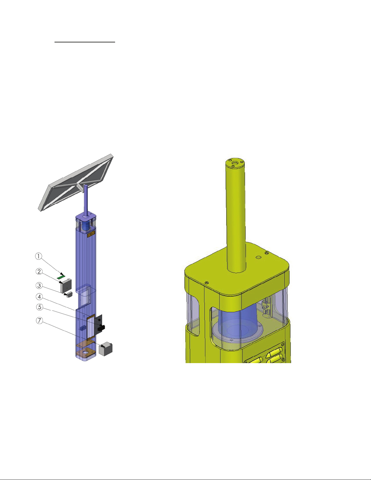
1. Remove the cap at the top of the tower with the solar mast and install the antenna mount,
antenna, and solar bracket and panels using the separate instructions for those items. Run the
solar power wires through the hole at the top of the mast using the included fitting. Extra cable
can be used to connect the two batteries.
2. Fasten the blue light/strobe to the tower with three (3) 10-24 pan head tamperproof screws. Feed
the power cord and control wires through to the tower.
3. Feed the solar power cable and the antenna cable through the two wire routing clips and into the
holes beneath the clips to run those cables into the main tower body. See Figure 2.
4. Secure the cap, with solar panels and antenna attached, back onto the top of the tower.
5. A polycarbonate light cover protects the LED light assembly from the inside. Peel the protective
film off the light cover and fit it onto the studs inside the tower. Slide the LED board over the studs
with the LEDs facing down. The built-in spacers will keep the LEDs from resting on the acrylic
window. Tighten down using the enclosed #6 nuts. Be careful not to over-tighten to avoid
cracking the circuit board.
6. Remove the aluminum plate from the tower and attach the Solar Controller using the included 4
screw and nuts. This is the where most of the wiring connections should be made.
7. Install one 3/4” nut and one washer on each anchor bolt 2.5” above grade to top of washer. This
will allow for a 1/2" air gap between the foundation and the tower which will allow airflow and
prevent moisture problems. Verify that the nuts are level (0° pitch).
NOTE: To insure proper grounding of all electrical components, the tower mount should be
effectively earth grounded from the grounding stud (located in the electrical box--see Figure 1)
with 6 AWG or better insulated, stranded copper wire to the metallic power service raceway
(conduit) or an 8' or longer corrosion-resistant ground spike.
After removing the cover plate from the tower’s rear access opening, install the tower onto the
bolts with the Emergency Phone opening oriented in the desired direction. Install second set of
nuts and washers. Tighten the upper nuts; the bottom set is only for leveling.
8. Connect the solar power wires to the SOLAR terminals on the Solar Controller. The remaining
power cable can be used to run from the BATTERY terminals on the Solar Controller to the 2
batteries, connected in parallel. Crimp on connectors are included for the batteries.
9. The blue light/strobe and LED faceplate light power wires should be connected to the LOAD
terminals on the controller.
10. Connect the antenna cable to the Cellular Interface or other wireless communications device, if
used. Cellular interfaces and VOIP-1's should be powered by the included DC/DC converter,
which has battery ring terminals pre-connected. The VOIP-RF-900, if used, should be powered
directly from the battery through the 12VDC internal connection.
11. The communications equipment (through the DC/DC converter, if needed) should be connected
directly to the battery. If the battery voltage drops, the solar controller will shut off power to the
LOAD terminals so as not to damage the battery. This will cause the lights to shut off. By
connecting the communications equipment directly, you will still be able to make emergency calls
for a little while after the lights shut off. Excessive drainage WILL damage the batteries, so if the
lights go off due to low voltage, you should promptly replace the batteries.
Make sure the DC/DC converter is set for the correct output voltage. The lowest effective voltage
should be used for maximum power efficiency. For Cellular units, this is 6 or 6.5VDC. The

ETP-MT/R OP SOLAR Tower Installation Instructions
Copyright 2009 Talk-A-Phone Co. All rights reserved.
Talk-A-Phone Co. • 7530 North Natchez Avenue • Niles, Illinois 60714-3804 Page 4 of 5
All prices and specifications are subject to change without notice.
Talk-A-Phone, Talk-A-Lert, Scream Alert and WEBS are registered trademarks of Talk-A-Phone Co.
DC/DC converter can be mounted inside the tower below the Cellular Device using the attached
double-sided Velcro.
12. Install the shelf and battery and make all remaining connections, including connecting the
batteries in parallel with the provided connector cable. NOTE: IT IS ESSENTIAL THAT THE
BATTERIES ARE CONNECTED IN PARALLEL AND NOT IN SERIES OR DAMAGE WILL
OCCUR TO THE SYSTEM.
13. Connect the black and orange wires of the Emergency Phone to the black and orange control
wires of the blue light/strobe. These are the AUX 2 output leads (see Emergency Phone manual
for programming). Plug the RJ11 connector on the emergency phone into the Cellular or other
communications device. Attach the Emergency Phone to the tower with six (6) 10-24 oval head
tamperproof screws.
14. Re-attach the cover plate over the access opening.
IV. ETP-MT/R OP SOLAR Wiring Diagram

ETP-MT/R OP SOLAR Tower Installation Instructions
Copyright 2009 Talk-A-Phone Co. All rights reserved.
Talk-A-Phone Co. • 7530 North Natchez Avenue • Niles, Illinois 60714-3804 Page 5 of 5
All prices and specifications are subject to change without notice.
Talk-A-Phone, Talk-A-Lert, Scream Alert and WEBS are registered trademarks of Talk-A-Phone Co.
V. 12VDC/24VDC/24VAC Strobe Wiring Diagram
It is the installer’s obligation to ensure compliance with all national, regional, and local regulations.
Table of contents
Other Talkaphone Conference System manuals