SOFTSTARTUK MIP-6 User manual

M
MI
IP
P-
-6
6
M
Mo
ot
to
or
r
I
In
ns
su
ul
la
at
ti
io
on
n
P
Pr
ro
ot
te
ec
ct
ti
io
on
n
I
In
ns
st
tr
ru
uc
ct
ti
io
on
n
M
Ma
an
nu
ua
al
l
Ver. 23/03/09

2 • Table of Content
________________________________________________________________________________________________
1. TABLE OF CONTENT
1. Table of Content ...................................................................................................................... 2
2. Safety & Warnings................................................................................................................... 3
2.1 Safety......................................................................................................................................... 3
2.2 Attention..................................................................................................................................... 3
2.3 Warnings.................................................................................................................................... 3
3. Technical Data ......................................................................................................................... 4
3.1 Introduction ................................................................................................................................ 4
3.2 Options....................................................................................................................................... 4
3.3 MIP selection ............................................................................................................................. 5
3.4 Protection features..................................................................................................................... 5
3.5 Input features ............................................................................................................................. 6
3.6 Supervision and communication features .................................................................................. 6
3.7 Optional serial link communication ............................................................................................ 6
4. Wiring Diagram ........................................................................................................................ 7
4.1 Low voltage wiring diagram ....................................................................................................... 7
4.2 Medium voltage wiring diagram ................................................................................................. 8
5. Terminals Description............................................................................................................. 9
6. Control Keypad...................................................................................................................... 11
6.1 LCD Arrangement .................................................................................................................... 11
6.2 Push-buttons............................................................................................................................ 11
6.3 Status LEDs. ............................................................................................................................ 12
6.4 Reviewing and modifying parameters...................................................................................... 12
6.5 Special actions performed by the key-pad............................................................................... 12
6.5.1 Run self test ..................................................................................................................12
6.5.2 Obtaining software version............................................................................................12
6.5.3 Obtaining default parameters ........................................................................................13
6.5.4 Clear statistical data ......................................................................................................13
6.5.4.1 Data cleared when STATISTICAL DATA is reset. .................................................13
6.5.5 Adjusting real time clock................................................................................................14
6.6 Mode pages ............................................................................................................................. 14
6.7 Blinking messages................................................................................................................... 15
6.8 Constant messages ................................................................................................................. 15
6.9 Mode pages and default values ............................................................................................... 16
6.9.1 Insulation parameters settings – page 1 .......................................................................18
6.9.2 I/O Parameters settings – page 2..................................................................................20
6.9.3 Tripping/alarm Options – page 3 ...................................................................................23
6.9.4 Comm. Parameters settings – page 4...........................................................................24
6.9.5 Measured data – page 5 ...............................................................................................25
6.9.6 Last 24 hour data – page 6 ...........................................................................................26
6.9.7 Last 31day data – page 7..............................................................................................26
6.9.8 256 months data – page 8.............................................................................................27
6.9.9 21 years data – page 9..................................................................................................27
6.9.10 Fault data – page 10 .....................................................................................................28
7. Case and Cutout Details ....................................................................................................... 29
8. Rear Panel Connection ......................................................................................................... 30
9. Resistor Units RU-7 & RU13 Dimensions............................................................................ 30
10. Technical Specifications....................................................................................................... 31
11. Ordering Information............................................................................................................. 32

3 • Safety & Warnings
2. SAFETY & WARNINGS
2.1 Safety
1 Read this manual carefully before operating the equipment and follow its
instructions.
2 Installation, operation and maintenance should be in strict accordance
with this manual, national codes and good practice.
3 Installation or operation not performed in strict accordance with these
instructions will void manufacturer warranty.
4 Disconnect all power inputs before servicing the MIP-6 and/or the load.
2.2 Attention
1 This product was designed for compliance with IEC 947-4-2 for class A
equipment.
2 Use of the product in domestic environments may cause radio
interference, in which case, the user may be required to employ
additional mitigation methods.
3 Utilization category is AC-53a or AC-53b, Form 1. For further information,
see Technical Specification
2.3 Warnings
1 Internal components and PCBs are at mains potential when the MIP-6 is
connected to mains. This voltage is extremely dangerous and will cause
death or severe injury if contacted.
2 When MIP-6 is connected to mains, even if control voltage is
disconnected, full voltage may appear on its internal PCBs.
3 The MIP-6 must be grounded to ensure correct operation, safety and to
prevent damage.
The company reserves the right to make any improvements or modifications to its products without
prior notice.
________________________________________________________________________________________________

4 • Technical Data
________________________________________________________________________________________________
3. TECHNICAL DATA
3.1 Introduction
Softstart UK’s MIP-6 is a sophisticated OFF-Line
Motor Insulation measure and Protection unit.
The MIP-6 is designed for testing the insulation resistance of both Low Voltage and Medium Voltage motors
(Low voltage model and Medium voltage models are different models).
For Low Voltage motors, the MIP-6 is a stand alone unit.
For Medium Voltage motors, external RU7 (up to 7200V) or RU13 (up to 13800V) should be used.
The MIP-6 is a fully digital unit and can be used for all types of AC motors.
The MIP-6 measures:
•Actual insulation resistance.
When the optional real time clock is installed, the optionMIP-6 is capable to calculate:
•Last hour average insulation resistance.
•Last twenty four hours average insulation resistance.
•Last (previous) month average insulation resistance.
•Last (previous) year average insulation resistance
Two types of Minimum and Maximum insulation resistance levels are recorded. One type is for
the present month and the other for minimum and maximum levels, since the last reset.
All above parameters can be displayed and read through the optional RS485 communication.
Built in programmable time delay, prevents wrong insulation measurement due to motor cable capacitances
and motor induced voltages.
The MIP-6 relay protects the system from abnormal low insulation resistance condition in the motor and
cabling. Upon fault, the MIP-6 can alarm or trip the motor or prohibit starting.
The MIP-6 uses automatically Adjustable DC voltage level for the optimal Insulation resistance measurement.
To increase system and user safety maximum DC voltage is 50V.
Insulation measurement range is 0 – 50Mohm for both low voltage and medium voltage types.
The MIP-6 measures the insulation level when the motor is off line. Measurement is performed only when the
upstream line contactor is open. A discrete (digital) input is used to inform the MIP-6 if it should measure the
insulation resistance or not.
The MIP-6 cannot measure the insulation resistance when motor is powered. No damage will occur if the MIP-
6 connected properly when the motor is powered.
To prevent mistake and high insulation resistance reading, as a result of a disconnected measurement line,
Line Test feature enables user to perform line test and verify that the insulation measurement line is properly
connected. This feature tests also that the MIP functions normally. This feature applicable only to M.V. units.
In addition, internal self test is running in the background and testing the MIP-6. Manual self test can be also
performed.
The MIP-6 is fully programmable with 8 protection functions, including Insulation Trip, Insulation Alarm, Line
Test fail (M.V. units only!), optional Communication Port failure, Internal Fault and three External Faults.
The MIP-6 has a two line, 16 character LCD display and a six buttons keyboard for programming, reading
actual values, statistical & maintenance data.
3.2 Options
1. Real time clock. More than 21 years of data can be stored in the MIP-6. Data will be lost if MIP-
6 is disconnected from the auxiliary power supply voltage, for more than 2 weeks.
The MIP-6 is capable of storing and displaying the following historical values:
•Average Insulation resistances, hour by hour, of the last 24 hours.
•Average Insulation resistances, day by day, of the last 31 days.
•Average Insulation resistances, month by month, of the last 256 months.
•Average Insulation resistances, year by year, of the last 21 years.

5 • Technical Data
________________________________________________________________________________________________
2. RS-485 communication for MIP-6 programming, remote data readings and controlling.
3. Analog output. The MIP-6 can output present insulation level, 1 hour average, 24 hours average or one
month average.
3.3 MIP selection
Select the MIP-6 according to mains rated voltage.
Low Voltage – Up to 690V line to line.
Medium Voltage 1 – up to 7200V line to line (together with RU7).
Medium Voltage 2 – up to 13800V line to line (together with RU13).
3.4 Protection features
The MIP-6 alarms if the motor ground insulation level decreases below a preset value. This relay should
protect the motor against too low insulation resistance between motor windings and ground (earth).
For low voltage, up to 690V, the MIP-6 is directly connected to one of the motor phases. For MV, all three
motor phases are connected to an external resistor and protection unit RU7/13. The output of the RU7/13 is
connected to the MIP-6.
The MIP-6 incorporates one programmable Analog Output (optional) as well as six programmable discrete
inputs and six programmable output relays. Four relays are of the N.O. type with one common line to all four.
The other two relays are change-over (form C) type.
All inputs and outputs are combined to provide a very flexible package.
All output relays can be programmed as: TEST COMMAND OFF (M.V. units only!), TEST COMMAND ON
(M.V. units only!),INS. TST NOT ACT., INS. TST ACTIVE, INSUL. IN RANGE D, INSUL. IN RANGE C,
INSUL. IN RANGE B, INSUL. IN RANGE A, FAULT-FAIL SAFE, FAULT, ALARM-FAIL SAFE, ALARM, TRIP-
FAIL SAFE, TRIP,
In addition to the above programming options for all relays, each of A, B or C relays can be configured as
TRIPPING/ALARM as shown on the following table:
(i.e. - It is possible to assign certain faults to each one of the relays A, B or C.)
The MIP-6 can handle 8 different trips / alarms.
INSULATION TRIP Programmable level normally used to prevent starting the motor.
INSULATION ALARM Programmable level normally used to alarm that the insulation level is
decreasin
g
.
COMM PORT FAILED Used to alert for a communication port fault.
LINE TEST FAILED Used to alert when insulation test line is faulty. Applicable only in MIP-6 for
Medium voltage application (with RU7 or RU13).
INTERNAL FAILURE Background running self test program continuously tests the hardware and
software of the MIP-6. This protection can signal if an internal error occurs.
EXTERNAL FAULT 1
EXTERNAL FAULT 2
EXTERNAL FAULT 3
Three external fault inputs can be programmed to alarm or trip the motor.
Protection levels and time delay settings are programmable using the key pad on the front panel or through
communication.
Note that other relays – D, E and F can not be programmed as a TRIPPING/ALARM relays.
Refer to section 6.9.3 on page 23 for more details.

6 • Technical Data
________________________________________________________________________________________________
3.5 Input features
Six optically isolated logic inputs are used. Each input can be programmed as: EXT FAULT 3 N.C., EXT
FAULT 3 N.O., EXT FAULT 2 N.C., EXT FAULT 2 N.O., EXT FAULT 1 N.C., EXT FAULT 1 N.O.,
EMERGENCY RESTART, AUTHORIZED KEY, REMOTE RESET, TEST LINE (M.V. units only!), TEST
INSUL. N.C., TEST INSUL. N.O.
3.6 Supervision and communication features
A Liquid Crystal Display (LCD), together with a keypad and LEDs enables “user friendly” interface, accurate
digital parameters setting, actual parameters readings, and detailed trip and alarm message displays.
Unauthorized setting changes can easily be prevented by the correct use of the Authorized key input terminals
and settings.
Measured Data Actual Insulation value, one hour average insulation value(1), 24 hours
insulation value(1), previous month average insulation(1), present month
minimum and maximum insulation values(1), minimum/maximum insulation
values since last reset, output and output contacts status
Last 24 Hours Data(1) Average insulation resistances, hour by hour, of the last 24 hours.
Lat 31 Day Data(1) Average insulation resistances, day by day, of the last 31 days.
256 Months Data(1) Average insulation resistances, month by month, of the last 256 months.
21 Years Data(1) Average insulation resistances, year by year, of the last 21 years.
Fault data Last Trip, Last Alarm, insulation resistance at time of trip, last 10 faults
with time and date stamp. (1)
Note:
(1) – Optional when real time clock option is installed.
3.7 Optional serial link communication
The MIP-6 is equipped with an optional powerful data communication system.
This communication system is unmatched in its reliability, flexibility and ease of use providing the ideal basis
for the design of a modern motor management system.
The MIP-6 incorporates a rear RS485 serial link that uses a MODBUS RTU protocol (The protocol description is not
included in this document) to provide high speed data acquisition to supervisory computers.
Data formats have been carefully structured to provide fast notification of alarms and continuous updates of performance
parameters.
The following information and control can be accessed through the communication.
(See MIP-6 Communication instruction manual.)
•All Actual data values
•All MIP-6 Parameter Settings (Read & Write)
•All the control commands for the MIP-6 (Measure command, Test line)
•Reset
The MIP-6 system is user expandable. No special engineering skills or tools are required.
For small systems, the host computer can communicate directly with the MIP-6 via a twisted shielded pair.
For larger systems a data highway enables multiple MIP-6 connection. Up to 32 MIP-6s can be added on
each twisted pair of the Host serial link with full access to all MIP-6's.
The system also performs high speed data acquisition. Users have a simple and friendly means of creating a
fully integrated monitoring and control systems.
System reliability is exceptionally high, meeting the highest standards of reliable communication in the
industry. Included in each message is a 16 bit CRC.
Notes:
•Protocols other than MODBUS RTU available upon consultation.
•Terminate serial link cable with 120 Ohm resistors at both ends.

7 • Wiring Diagram
4. WIRING DIAGRAM
4.1 Low voltage wiring diagram
Notes:
(1) – The optional communication RS485 output is an isolated output.
Use shielded twisted pair for RS485 communication.
It is recommended to ground the shield near the MIP-6.
(2) – The optional analog output is an isolated output.
Use shielded twisted pair for analog output.
It is recommended to ground the shield of the analog output cable at the receiver side.
(3) – All output relays are programmable. Refer to section 6.9.2 page 20 for more details.
(4) – All input relays are programmable. Refer to section 6.9.2 page 20 for more details.
(5) – Leave terminals 51, 52 not connected.
________________________________________________________________________________________________
8 • Wiring Diagram
________________________________________________________________________________________________
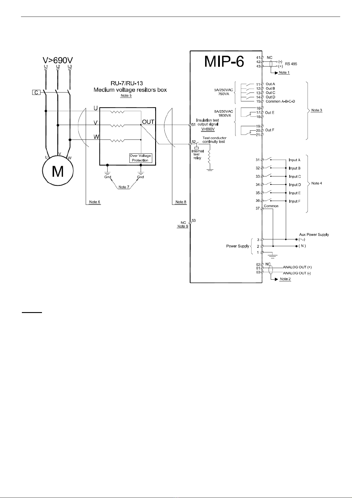
4.2 Medium voltage wiring diagram
Notes:
(1) – The optional communication RS485 output is an isolated output.
Use shielded twisted pair for RS485 communication.
It is recommended to ground the shield near the MIP-6.
(2) – The optional analog output is an isolated output.
Use shielded twisted pair for analog output.
It is recommended to ground the shield of the analog output cable at the receiver side.
(3) – All output relays are programmable. Refer to section 6.9.2 page 20 for more details.
(4) – All input relays are programmable. Refer to section 6.9.2 page 20 for more details.
(5) – RU7 is applicable for voltage up to 7.2kV.
RU13 is applicable for voltage up to 13.8kV.
(6) – Use medium voltage leads to connect the RU7/13 to the M.V. motor.
(7) –Use two ground connection to ground the RU7/13.
(8) – Use low voltage leads from RU7/13 to MIP-6 unless these leads run near M.V.
exposed equipment.
(9) – Leave terminal 53 not connected.

9 • Terminals Description
________________________________________________________________________________________________
5. TERMINALS DESCRIPTION
Indication Description Remarks
Terminal 3 – Phase or DC (+)
Terminal 2 – Neutral or DC (-)
Terminal 1 – Ground
Control voltage.
85-230VDC/AC (50/60Hz)
Same unit for all range of auxiliary
power supply. No need for
adjustments of any kind.
Terminal 31 – Input A
Terminal 32 – Input B
Terminal 33 – Input C
Terminal 34 – Input D
Terminal 35 – Input E
Terminal 36 – Input F
Terminal 37 – Common
Discrete Inputs.
6 programmable discrete
inputs.
To turn ON an input connect
control voltage between it’s
terminal and the common
terminal 37.
Each input can be programmed as:
EXT FAULT 3 N.C.
EXT FAULT 3 N.O.
EXT FAULT 2 N.C.
EXT FAULT 2 N.O.
EXT FAULT 1 N.C.
EXT FAULT 1 N.O.
EMERGENCY RESTART
AUTHORIZED KEY
REMOTE RESET
TEST LINE (M.V. units only!)
TEST INSUL. N.C.
TEST INSUL. N.O.
Refer to section 6.9.2 on page 20 for
more details.
Terminal 11 – Output relay A N.O
Terminal 12 – Output relay B N.O
Terminal 13 – Output relay C N.O
Terminal 14 – Output relay D N.O
Terminal 15 – Common of output
relays A, B, C & D.
Terminal 16 – Common of output
relay E
Terminal 17 – Output relay E N.C
Terminal 18 – Output relay E N.O
Terminal 19 – Common of output
relay F
Terminal 20 – Output relay F N.C
Terminal 21 – Output relay F N.O
Discrete Outputs.
6 programmable discrete
outputs.
Discrete outputs A, B, C, D
rated 5A/250VAC resistive,
750VA, NO configuration with
common terminal.
Discrete outputs E, F rated
8A/250VAC resistive,
1800VA inductive, change
over (form C) configuration.
Each output can be programmed as:
TRIPPING/ALARM (relays A, B and
C only!)
TEST COMMAND OFF
TEST COMMAND ON
INS. TST NOT ACT.
INS. TST ACTIVE
INSUL. IN RANGE D
INSUL. IN RANGE C
INSUL. IN RANGE B
INSUL. IN RANGE A
FAULT-FAIL SAFE
FAULT
ALARM-FAIL SAFE
ALARM
TRIP-FAIL SAFE
TRIP
Refer to section 6.9.2 on page 20 for
more details.
Terminal 43 – Serial port (+)
Terminal 42 – Serial port (-)
Serial link (Optional)
Standard RS485 half
duplex, with MODBUS
protocol.
Twisted shielded pair should
be used for wiring. Shield
should be connected to
chassis ground externally,
near the MIP-6.
Acceptable baud rates: 2400,
4800, 9600, 19200 and
38400 BPS.
Refer to section 3.7 on page 6for
more details.
Refer to section 6.9.4 on page 24 for
more programming details.
Note:
Connect 120 Ohm resistors
between (+) and (-) at both sides
of the line.

10 • Terminals Description
________________________________________________________________________________________________
Indication Description Remarks
Terminal 51 – Medium voltage
insulation input.
Terminal 52 – Medium voltage line
test input.
Terminal 53 – Low voltage
insulation input.
Insulation inputs
For Low voltage, up to 690V line to line, use terminal 53 only. Leave
terminals 51 and 52 open. Terminal 53 should be connected directly
to one of the motor phases. Terminal 53 can be connected to AC
voltage (when live) of 400V maximum (690/1.73), without damage.
There is no line test for low voltage.
WARNING! Terminal 53 is the only, terminal that can be
connected directly to mains live voltage of up to 690V
line to line. Connecting any live voltage to terminals 51
and/or 52 will cause immediate damage to the MIP-6
and can be dangerous!!!
Terminals 51 and/or 52 must be connected to
mains only through RU7 (up to 7200V) or RU13
(up to 13800V) unit. !
For Medium Voltage, use terminals 51 and 52. Terminal 51 is used
for the insulation measurement and terminal 52 is used for the line
test. Both terminals should be connected to motor via resistors unit
RU7/13. It is recommended to use two separate cables. One from
terminal 51 to the RU7/RU13 output and the other from terminal 52
to the RU7/RU13 output. Upon Line test, internal resistor is
connected to ground on terminal 52. Terminal 51 should measure
the parallel resistance of motor insulation and the internal resistance.
Terminal 61 – Analog out (+)
Terminal 63 – Analog out (-)
Analog output (Optional)
Analog output type can be
programmed to 4..20 mA or
0..20 mA. Load resistance
should be less than 400Ω.
Note:
The analog output electronics
is fully isolated electronic
circuitry.
Twisted and Shielded cable
must be used. Shield should
be connected to ground
externally, near the analog
output signal receiver.
The Analog output can be
programmed to represent one of
following parameters:
INS. R. AVG. -1MNTH(1)
INS. RES. AVG. -24H(1)
INS. RES. AVG. -1H(1)
INSULATION RES.
Refer to section 6.9.2 on page 20 for
more details.
Note:
(1) – Applicable only when real time
clock option is installed.

11 • Control Keypad
________________________________________________________________________________________________
6. CONTROL KEYPAD
The control keypad is the link between the MIP-6 and the user.
The MIP-6 control keypad features:
(1) Three indication LEDs (On, Stand by/Active, Fault/Alarm)
(2) Two lines of 16 alphanumeric characters each.
(3) Six push-buttons (Page, Select/Reset, Select, Store, Up (S) and down (T) keys.
(1)
(2)
(3)
6.1 LCD Arrangement
CONFIG. INPUT A
TEST INSUL. N.O.
Upper line displays function.
Lower line displays setting and\or measured values.
6.2 Push-buttons
Allows the operator to browse through the display and programming menus available in the
MIP-6.
Allows the operator to select a function within each Page.
Note: Pressing Select continuously changes shown parameters continuously.
Allows the operator to increase adjusted values shown in the display. Operator should press this
button momentarily, for slow value changes in the display, or continuously, for rapid value
changes in the display.
Allows the operator to decrease adjusted values shown in the display. Operator should press this
button momentarily, for slow value changes in the display, or continuously, for rapid value
changes in the display.
Page
Select
Allows the operator to store modified parameters in the non-volatile memory to save modified
parameters.
When Store is pressed while actual value is displayed, this display becomes the default display.
Store
12 • Control Keypad
________________________________________________________________________________________________
This key has two functions:
•Used to toggle between “backwards” and “forward” while pressing Select key.
When pressing Selectukey, an underline mark will show/not show on the first digit
of the second row of the display. While underline mark shows – Select key goes
“backwards”.
While underline mark does not show – Select key goes “forward”.
•When MIP-6 is in latched trip or in alarm status the Reset key allows the user to
reset the unit. The Reset key has to be pressed for 1 second in order to reset the
MIP-6.
Selectu
Reset
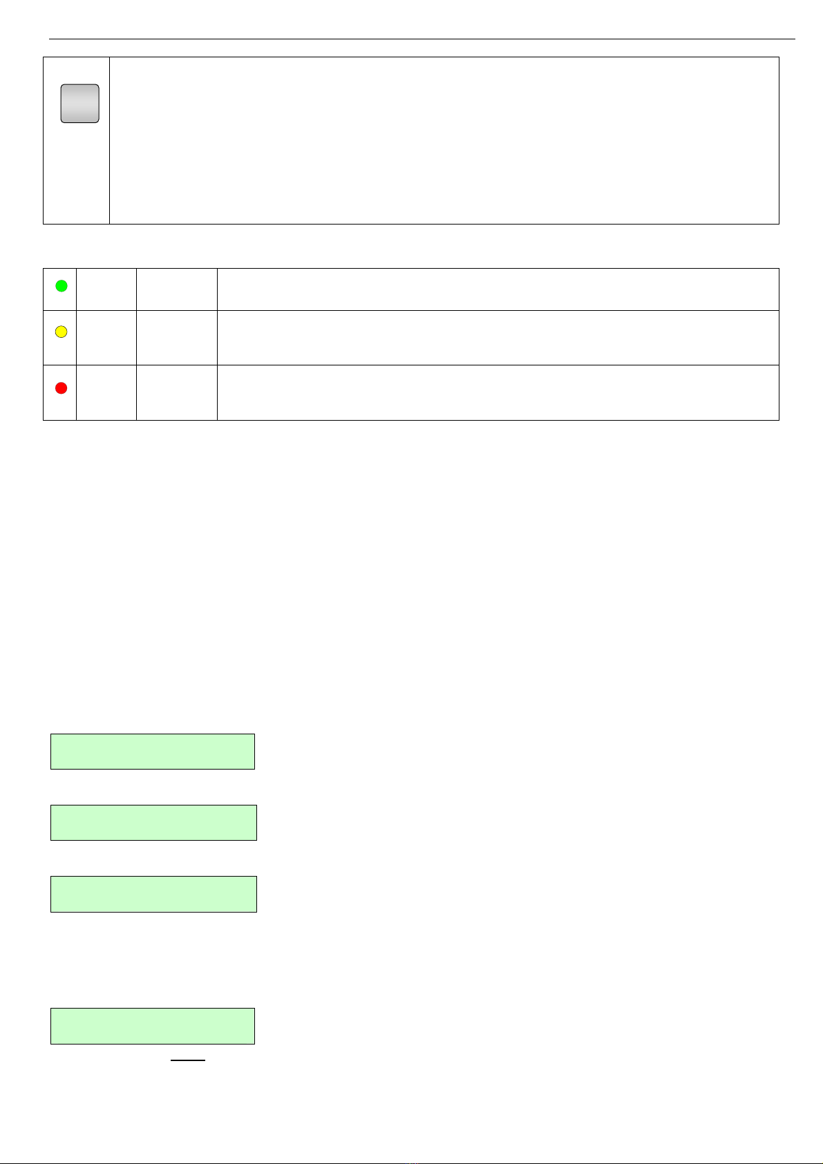
6.3 Status LEDs.
Green On Lights when control supply voltage is connected to the MIP-6.
Yellow Stand-by/
Active
Blinks when in stand-by.
Lights when measurement is active.
Red Alarm/
Fault
Blinks when in alarm.
Lights when in fault condition.
6.4 Reviewing and modifying parameters
Press Page key several times until you reach the required Mode page.
Press Select key to review parameters of this Mode.
When reaching the required parameter, modify its values with Tor Skeys.
Once value is set press Store key. Once data was properly stored in the non-volatile memory, the LCD will
display DATA SAVED OK for 2 seconds.
In addition the modified parameter/s can be stored at the end of every mode page.
Press Select until STORE ENABLE XXX PARAMETERS message appears, then press Store key. The LCD
will display DATA SAVED OK for 2 seconds.
6.5 Special actions performed by the key-pad.
6.5.1 Run self test
Press Page and Tkeys simultaneously.
The LCD will display:
TEST / MAINTENANCE
***OPTIONS***
Press Select key.
The LCD will display:
RUN SELF TEST?
PUSH ‘VALUE-UP’
To perform a self test push UP ARROW.
If self test OK, display will show:
SELF TEST PASSED
Press Mode key to exit test/maintenance mode.
6.5.2 Obtaining software version
Press Page and Tkeys simultaneously.
The LCD will display:
TEST / MAINTENANCE
******OPTIONS***********
Press Select key twice.
The LCD will display the software version:

13 • Control Keypad
________________________________________________________________________________________________
BTL-04/10/2006
MIP6-051006-Mb
Press Mode key to exit test/maintenance mode
6.5.3 Obtaining default parameters
Press Page and Tkeys simultaneously.
The LCD will display:
TEST / MAINTENANCE
******OPTIONS***********
Press Select key three times.
The LCD will display:
STORE NOW ?
DEFAULT SETTINGS
To obtain “default parameters” press Page+Store simultaneously.
The LCD will display:
DATA SAVED OK
At this point (If “default parameters” were obtained) the MIP-6 exit test/maintenance mode.
CAUTION! Obtaining Default Parameters erases all previously modified settings and
requires the operator to program all parameters values again.
6.5.4 Clear statistical data
Press Page and Tkeys simultaneously.
The LCD will display:
TEST / MAINTENANCE
******OPTIONS***********
Press Select key four times.
The LCD will display:
CLEAR NOW ?
STATISTICAL DATA
To clear “statistical data” press Reset+Store simultaneously.
The LCD will display:
DATA SAVED OK
At this point (If “statistical data” is cleared) the MIP-6 exit test/maintenance mode.
6.5.4.1 Data cleared when STATISTICAL DATA is reset.
The following data is cleared when STATISTICAL DATA is cleared:
•Total measure time
•Total # of trips
•Min. Insulation Resistances (general and of present month)
•Max. Insulation Resistances (general and of present month)
•Pre Trip Insulation value
•Last Trip
•Last Alarm
•Previous trips information and time stamps
•Hour, Date, Month, Year arrays with Insulation resistance history !
CAUTION! After clearing statistical data it is not possible to retrieve any cleared values.

14 • Control Keypad
________________________________________________________________________________________________
6.5.5 Adjusting real time clock
Press Page and Tkeys simultaneously.
The LCD will display:
TEST / MAINTENANCE
******OPTIONS***********
Press Select key five times.
The LCD will display:
hh.mm dd.mm.yy
09:10 29/11/06
Pay attention to the under line mark under the hour value.
modify the hour value with Tor Skeys.
Press Store key.
The LCD will display:
DATA SAVED OK
And after few seconds will change to:
hh.mm dd.mm.yy
09:10 29/11/06
Pay attention to the under line mark under the minutes value.
Repeat the same procedure as for the hour settings to seconds, day, month and year settings.
After Store key is pressed last time the LCD will display:
DATA SAVED OK
At this point the MIP-6 exit test/maintenance mode.
NOTE! For longer life, the Real Time Clock uses a backup capacitor and not a backup
battery. The backup capacitor retains data and keeps clock running for a few
days.
If the MIP-6 is not powered for a longer period, the clock has to be initialized.
Initialization can be done manually as described above or through a serial link.
6.6 Mode pages
Upon initiation of the MIP-6, the LCD displays:
INSULATION PARA.
***SETTINGS***
By pressing the Page key all mode pages can be reviewed:
I/O PARAMETERS
***SETTINGS***
TRIPPING/ALARM
***OPTIONS***
COMMUNICATION P.
***SETTINGS***
MEASURED DATA
-****-
LAST 24 HOUR DATA
-****-
LAST 31 DAY DATA
-****-
256 MONTHS DATA
-****-
21 YEARS DATA
-****-
FAULT DATA
-****-

15 • Control Keypad
________________________________________________________________________________________________
Notes:
1. Pressing Store key while the LCD displays an "Actual Data" parameter, will store this parameter as default
display. If no key is pressed for more than five minutes, this parameter will be constantly displayed.
2. Pressing Store key, while the LCD displays a header, will store this header as the default display. If no key
is pressed for more than five minutes this header will be constantly displayed.
6.7 Blinking messages
Blinking messages are displayed as a response to an event.
Blinking message is displayed for 2 seconds and then the display returns to the previous message.
Blinking messages are usually displayed as a response to an operator action.
The messages are either to confirm activation of the requested operation, or to indicate a reason for not doing
so.
Display Description
DATA SAVED OK
Displayed after pressing Store key. If an error is found during store
process, then next message is shown.
STORAGE ERROR
Displayed when an error is found in the store process.
WRONG PARAMETERS
Displayed after power-up, if the non-volatile parameter check sum is
found to be wrong.
UNAUTHRIZED ACCESS
When Authorized Key is open (locked), and a parameter change is
attempted. Also displayed after Unauthorized Store and Reset
action.
SELF TEST PASSED
Displayed as a response to running the built in test procedure,
provided that all tests were "OK".
SELF TEST FAILED
ERROR CODE=32
Displayed as a response to finding an error during the operation of
test procedure.
In case of test failure, reset and test again. If problem persists then
error code should be reported to an authorized factory
representative.
6.8 Constant messages
Constant messages are displayed upon a fault.
Display Description
ALARM
LINE TEST FAILED
Displayed when the Alarm LED illuminates. The lower line displays
the Alarm name.
TRIP
INSULATION TRIP
Displayed when the Trip LED illuminates. The lower line displays
the Trip name.
ALARM:
INT. FAILURE=XX
Displays in case of an internal failure.
Error code should be reported to an authorized factory
representative.

16 • Control Keypad
________________________________________________________________________________________________
6.9 Mode pages and default values
INSULATION PARA.
***SETTINGS*** I/O PARAMETERS
***SETTINGS*** TRIPPING/ALARM
***OPTIONS*** COMMUNICATION P.
***SETTINGS*** MEASURED DATA
--****--
See page 18 See page 20 See page 23 See page 24 See page 25
Display and default
values Display and default
values Display Display
WAIT BEFORE TEST
2 MIN
CONFIG. INPUT A
TEST INSUL. N.O.
BAUD RATE
19200
INSULATION RES.
34377 KOHM
INSUL. TRIP LVL
1.0 MOHM
CONFIG. INPUT B
TEST LINE
ADDRESS NUMBER
OFF
1 HOUR AVG. INSUL
23456 KOHM
INSUL. TRIP DLY
10 MIN.
CONFIG. INPUT C
REMOTE RESET
S.LINK PAR. SAVE
DISABLE
24 HOUR AVG. INSUL
24456 KOHM
INSUL. ALARM LVL
2.0 MOHM
CONFIG. INPUT D
AUTHORIZED KEY
S.LINK CONTROL
DISABLE
PREV. MONTH AVG.
34566 KOHM
INSUL. ALARM DLY
10 MIN.
CONFIG. INPUT E
EXT FAULT 1 N.O.
FRONT COM ADDRES
OFF
THIS MONTH MIN.
12345 KOHM.
INSUL. RANGE A
4.0 MOHM
CONFIG. INPUT F
EXT FAULT 2 N.O.
STORE ENABLE
COMM. PARAMETERS
THIS MONTH MAX.
4321 KOHM.
INSUL. RANGE B
6.0 MOHM
PARAM. SETTINGS
NOT LOCKED
MINIMUM INSUL. R
34521 KOHM.
INSUL. RANGE C
8.0 MOHM
CONFIG. OUTPUT A
INSUL. IN RANGE D
MAXIMUM INSUL. R
99888 KOHM.
INSUL. RANGE D
10.0 MOHM
OUTPUT DELAY
600 SEC.
IN # 1 2 3 4 5 6
0 1 1 0 0 0
DISPLAY MODE
FULL DISPLAY
CONFIG. OUTPUT B
INSUL. IN RANGE C
OUT # 1 2 3 4 5 6
0 1 1 0 0 0
STORE ENABLE
INSULATION PARA.
OUTPUT DELAY
600 SEC.
TOTAL MEASURE T.
2 HOURS
CONFIG. OUTPUT C
INSUL. IN RANGE B
TOTAL # OF TRIPS
0
OUTPUT DELAY
600 SEC.
CONFIG. OUTPUT D
INSUL. IN RANGE A
OUTPUT DELAY
600 SEC.
CONFIG. OUTPUT E
ALARM
OUTPUT DELAY
300 SEC.
CONFIG. OUTPUT F
TRIP
ANALOG OUT TYPE
4 . . 20 mA
OUTPUT DELAY
120 SEC.
ANALOG OUT PARAM.
INS. RES. AVG. -1H
ANALOG OUT MIN.
0.0 MOHM
ANALOG OUT MAX.
20.0 MOHM
STORE ENABLE
I/O PARAMETERS

17 • Control Keypad
________________________________________________________________________________________________
LAST 24 HOUR DATA
--****-- LAST 31 DAY DATA
--****-- 256 MONTHS DATA
--****-- 21 YEARS DATA
--****-- FAULT DATA
--****--
See page 26 See page 26 See page 27 See page 27 See page 28
Display Display Display Display Display
PREVIOUS INSUL.:
AVARAGE VALUES
PREVIOUS INSUL.:
AVARAGE VALUES
PREVIOUS INSUL.:
MONTH/YEAR
PREVIOUS INSUL.:
MONTH/YEAR
LAST ALARM
INTERNAL FAILURE
HOUR=0….. 23
52.6 MOHM
DATE=1….. 31
51.3 MOHM
04/00 AVG, MIN, MX
60.0 60.0 60.0 M
04/00 AVG, MIN, MX
60.0 60.0 60.0 M
PRE TRIP INSUL.
0 KOHM
PREVIOUS INSUL.:
AVARAGE VALUES
LAST 10 TRIPS:
HH:MM DD/MM/YY

18 • Control Keypad
________________________________________________________________________________________________
6.9.1 Insulation parameters settings – page 1
INSULATION PARA.
***SETTINGS***
Display and default
values Range Description
WAIT BEFORE TEST
2 MIN
0 – 960 min. Idle time after measure command. Insulation measurement
starts after the WAIT BEFORE TEST TIME has elapsed.
INSUL. TRIP LVL
1.0 MOHM
0.2 – 25 MOhm. Trip occurs when present value of measured resistance is
lower than INSUL. TRIP LVL, for more than INSUL. TRIP
DLY (See next parameter)
Note:
In order to be activated, this parameter must be
programmed to:
I/O PARAMETERS SETTINGS – Parameters CONFIG.
OUTPUT X (Refer to section 6.9.2 page 20 for more details)
TRIPPING/ALARM OPTIONS (Refer to section 6.9.3 page
23 for more details)
INSUL. TRIP DLY
10 MIN.
0 – 960 min. Time Delay of Insulation trip.
INSUL. ALARM LVL
2.0 MOHM
0.2 – 25 MOhm. Alarm occurs when present value of measured resistance is
lower than INSUL. ALARM LVL, for more than INSUL.
ALARM DLY (See next parameter)
Note:
In order to be activated, this parameter must be
programmed to:
I/O PARAMETERS SETTINGS – Parameters CONFIG.
OUTPUT X (Refer to section 6.9.2 page 20 for more details)
TRIPPING/ALARM OPTIONS (Refer to section 6.9.3 page
23 for more details)
INSUL. ALARM DLY
10 MIN.
0 – 960 min. Time Delay of Insulation alarm.
INSUL. RANGE A
4.0 MOHM
0.2 – 25 MOhm. Insulation is inside range A (can operate a relay for
signalling) when measured Insulation resistance is lower
than INSUL. RANGE A setting.
INSUL. RANGE B
6.0 MOHM
0.2 – 25 MOhm. Insulation is inside range B (can operate a relay for
signalling) when measured Insulation resistance is lower
than INSUL. RANGE B setting.
INSUL. RANGE C
8.0 MOHM
0.2 – 25 MOhm. Insulation is inside range C (can operate a relay for
signalling) when measured Insulation resistance is lower
than INSUL. RANGE C setting.
INSUL. RANGE D
10.0 MOHM
0.2 – 25 MOhm. Insulation is inside range D (can operate a relay for
signalling) when measured Insulation resistance is lower
than INSUL. RANGE D setting.
DISPLAY MODE
FULL DISPLAY
FULL DISPLAY Future enhancement.
STORE ENABLE
INSULATION PARA.
Storing modified parameters
To store selected parameters, press Store key.
Note: Storing more than one parameter possible only when

19 • Control Keypad
________________________________________________________________________________________________
INSULATION PARA.
***SETTINGS***
Display and default
values Range Description
the MIP-6 is not running.
While MIP-6 is running each parameter can be changed
individually by pressing Store key after modifying the
parameter.
When parameters are correctly stored, the LCD will read:
DATA SAVED OK
This concludes INSULATION PARAMETER settings.
Pressing Select key after DATA SAVED OK returns to the
first display in this mode.
Note:
In case of a failure in parameter storing, the LCD
displays:
STORAGE ERROR
In this case load MIP-6 default parameters. Refer to section
6.5.3 on page 13 for more details on loading MIP-6 default
parameters.

20 • Control Keypad
________________________________________________________________________________________________
6.9.2 I/O Parameters settings – page 2
I/O PARAMETERS
***SETTINGS***
Display and default
values Range Description
CONFIG. INPUT A
TEST INSUL. N.O.
EXT FAULT 3 N.C.
EXT FAULT 3 N.O.
EXT FAULT 2 N.C.
EXT FAULT 2 N.O.
EXT FAULT 1 N.C.
EXT FAULT 1 N.O.
EMERGENCY
RESTART
AUTHORIZED KEY
REMOTE RESET
TEST LINE
TEST INSUL. N.C.
TEST INSUL. N.O.
Sets MIP-6 INPUT A.
EXT FAULT 3 N.C. (1) is programmed for open to trip.
EXT FAULT 3 N.O.(1) is programmed for close to trip.
EXT FAULT 2 N.C.(1) is programmed for open to trip.
EXT FAULT 2 N.O.(1) is programmed for close to trip.
EXT FAULT 1 N.C.(1) is programmed for open to trip.
EXT FAULT 1 N.O.(1) is programmed for close to trip.
EMERGENCY RESTART is programmed to reset and
prevent insulation trip by the MIP-6. (See also PARAM.
SETTING below)
AUTHORIZED KEY is programmed to prevent
parameter modifications. Closing the contact will
enable programming the MIP-6.
REMOTE RESET is programmed to remote reset the
MIP-6. To remote reset close contact momentarily.
TEST LINE is programmed to start the wiring test of the
cable from the resistor unit (RU7/RU13). Close the
contact to start the insulation measurement.
Applicable only in medium voltage applications.
TEST INSUL. N.C. is programmed to start the
insulation measurement. Open the contact to start the
insulation measurement.
TEST INSUL. N.O. is programmed to start the
insulation measurement. Close the contact to start the
insulation measurement
Note:
(1) In order to be activated, this parameter must be
programmed to:
I/O PARAMETERS SETTINGS – Parameters CONFIG.
OUTPUT X (Refer to section 6.9.2 page 20 for more
details)
TRIPPING/ALARM OPTIONS (Refer to section 6.9.3
page 23 for more details)
CONFIG. INPUT B
TEST LINE
Same as for CONFIG.
INPUT A.
CONFIG. INPUT C
REMOTE RESET
Same as for CONFIG.
INPUT A.
CONFIG. INPUT D
AUTHORIZED KEY
Same as for CONFIG.
INPUT A.
CONFIG. INPUT E
EXT FAULT 1 N.O.
Same as for CONFIG.
INPUT A.
CONFIG. INPUT F
EXT FAULT 2 N.O.
Same as for CONFIG.
INPUT A.
PARAM. SETTINGS
NOT LOCKED
LOCKED OUT
NOT LOCKED
When set to LOCKED OUT, AUTHORIZED KEY
programming in CONFIG INPUT A (See above)
functions normally.
Table of contents


