Tradinco TRAQC-9 User manual

User Manual
TRAQC-9
TRAQC-9
Calibrators
User Manual

User Manual
TRAQC-9
TRAQC-9 04/2017 EN Rev.4 page : 2
Content
1. General 5
1.1 Warranty .........................................................................................5
1.2 TRAQC-9 Description.........................................................................6
1.2.1 CE EMC Directive 2014/30/EU ........................................................6
1.2.2 CE Electrical Safety Directive 2014/35/EU........................................6
1.3 Symbols Used ..................................................................................7
1.4 Scope of this manual ........................................................................7
1.5 Indicator Interface............................................................................8
1.6 Navigation .......................................................................................9
1.7 Electrical Connections .....................................................................10
2. TRAQC-9 Types 11
2.1 TRAQC-9 Configurations ..................................................................11
2.2 TRAQC-9 P Pressure........................................................................12
2.3 TRAQC-9 MAVS Milliamp ere and Volt Signals........................................13
2.4 TRAQC-9 CAC Absolute pressure Controller........................................14
2.4.1 TRAQC-9 CAC operating instructions:............................................14
2.5 TRAQC-9 CPC Pneumatic Controller ..................................................15
2.5.1 TRAQC-9 CPC operating instructions: ............................................15
2.6 TRAQC-9 CLPC Low Pressure Controller .............................................16
2.6.1 The TRAQC-9 CLPC operating instructions: ....................................16
2.7 TRAQC-9 CHPC High Pressure Controller............................................17
2.7.1 TRAQC-9 CHPC Operating instructions: .........................................17
2.8 TRAQC-9 CVC ................................................................................18
2.8.1 TRAQC-9 CVC operating instructions:............................................18
3. Operating Instructions 19
3.1 Power On/Off ................................................................................. 19
3.2 Menu ............................................................................................19
3.2.1 Main Menu Structure ...................................................................19
3.3 Zeroing ......................................................................................... 20
3.4 Selecting Pressure Units ..................................................................20
3.5 Pressure Range .............................................................................. 21
3.5.1 Selecting Pressure sensor Auto ranging .........................................21
3.6 Instrument Status ..........................................................................21
4. User Configuration 22
4.1 Pressure Setup...............................................................................22
4.1.1 Averaging on/off.........................................................................22
4.1.2 Averaging setup .........................................................................22
4.1.3 Resolution Setup ........................................................................22
4.1.4 Conversion Table ........................................................................23
4.1.5 Set customer unit .......................................................................23
4.1.6 Gauge mode ..............................................................................23
4.1.7 Absolute mode ...........................................................................23
4.1.8 Set abs interval ..........................................................................23
4.1.9 Set Baro.ref.int ..........................................................................23
4.2 Electrical Input Setup......................................................................24
4.2.1 mA Input ...................................................................................24
4.2.2 mA + Xmtr Supply (optional) .......................................................24
4.2.3 Xmtr Power Setup (optional)........................................................ 24
4.2.4 Switch Test................................................................................25
4.2.5 Switch Test Setup.......................................................................25
4.2.6 V Input......................................................................................25
4.2.7 Hart Resistor..............................................................................25
4.2.8 mA/V Scaling .............................................................................26
4.2.9 Set mA/V Scaling....................................................................... 26
4.3 Electrical Output Setup (Optional) ....................................................27

User Manual
TRAQC-9
TRAQC-9 04/2017 EN Rev.4 page : 3
4.3.1 Pressure xmtr mode (Pressure transmitter mode)...........................27
4.3.2 Xmtr mode settings (Parameter Mode Settings)..............................28
4.3.3 Current Output...........................................................................28
4.3.4 Current Output Settings ..............................................................28
4.3.5 Voltage Output...........................................................................29
4.3.6 Voltage Output Settings .............................................................. 29
4.3.7 Auto Span Check Mode................................................................29
4.3.8 Ramp Mode ...............................................................................29
4.4 Instrument Configuration ................................................................30
4.5 Memory functions ...........................................................................32
4.6 Temperature ..................................................................................32
4.7 Advanced Options...........................................................................32
4.7.1 Set rtc time ...............................................................................32
4.7.2 Set rtc date ...............................................................................32
4.7.3 Set recal Date ............................................................................33
4.7.4 Erase data memory.....................................................................33
4.7.5 Show Product Data .....................................................................33
4.8 Calibration of TRAQC-9.................................................................... 34
4.8.1 Adjust instrument inputs. ............................................................34
4.8.1.1 Current input .........................................................................35
4.8.1.2 Current in + Loop supply (Optional) ..........................................35
4.8.1.3 Voltage input .........................................................................35
4.8.1.4 Adjust Vbat A/D .....................................................................36
4.8.1.5 P1: XX-YY BARG (Pressure Sensor Adjustment) .......................... 36
4.8.1.6 Clear user adjustments ...........................................................36
4.8.1.7 Resistance input .....................................................................36
4.8.2 Adjust instruments outputs (Optional)...........................................37
4.8.2.1 Current source ....................................................................... 37
4.8.2.2 Current simulator ...................................................................37
4.8.2.3 Voltage output .......................................................................38
4.8.3 Show calibration factors ..............................................................38
5. Data transfer 39
6. Computer Interface (Optional) 39
6.1 General Description ........................................................................39
6.2 Connections ................................................................................... 39
6.3 RS232 Settings ..............................................................................39
6.4 Ethernet Settings ...........................................................................39
7. Maintenance instructions 40
7.1.1 Housing.....................................................................................40
7.1.2 Test connections.........................................................................40
7.1.3 Regulating valves .......................................................................40
8. Product Specifications 41
8.1 General .........................................................................................41
8.2 Measurement .................................................................................41
8.3 Generation and control....................................................................41
8.3.1 Traqc-9 P ..................................................................................41
8.3.2 Traqc-9 CLPC Low Pressure Controller ........................................... 41
8.3.3 Traqc-9 CHPC High Pressure Controller..........................................41
8.3.4 Traqc-9 CPC Pressure Controller ...................................................41
8.3.5 Traqc-9 CVC Vacuum Controller ...................................................42
8.3.6 Traqc-9 CAC Absolute Pressure Controller...................................... 42
8.4 Options & Accessories .....................................................................43
8.4.1 Standard Supply includes ............................................................43
8.4.1.1 TRAQC-9 P /MAVS ..................................................................43
8.4.1.2 TRAQC-9 Controller.................................................................43
8.4.2 Optional Supply..........................................................................43

User Manual
TRAQC-9
TRAQC-9 04/2017 EN Rev.4 page : 4

User Manual
TRAQC-9
TRAQC-9 04/2017 EN Rev.4 page : 5
1. General
1.1 Warranty
During the design and manufacturing of this instrument the at most attention has been given to
quality and durability.
This manual contains information needed for the safe and effective use of the
capabilities of the instrument.
Please read the manual carefully before operating the instrument. By doing so
possible damage to the instrument or damage caused by the incorrect use of the
instrument can be avoided.
TRADINCO INSTRUMENTS warrantees the instrument in accordance with the Standard Terms
and Conditions of the Instrument Trade as issued by the Association bearing the name
"Federation Het Instrument" (The Instrument Federation, (filed with the Clerk of Utrecht District
Court on 13 January 1993 under number 16/93 and with the Chamber of Commerce and
Industry in Amersfoort on 18 January 1993. A copy is available on request.
TRADINCO INSTRUMENTS warrantees that this product will be free from defects in materials
and workmanship for a period of 5 years from the date of shipment. If any such product proves
defective during this warranty period, TRADINCO INSTRUMENTS, at its option, will either repair
the defective product without charge for parts or labour, or will provide a replacement in
exchange for the defective product.
In order to obtain service under this warranty, Customer must notify TRADINCO INSTRUMENTS
of the defect before the expiration of the warranty period and make suitable arrangements for
the performance of the service.
Customer shall be responsible for packaging and shipping of the defective product to the service
centre designated by TRADINCO INSTRUMENTS, with shipping charges prepaid.
If no defect can be found Customer may be charged for costs of the investigation.
This warranty does not apply to any defect, failure or damage caused by:
a. Improper use of the instrument.
b. Battery leakage.
c. Normal wear of the product.
d. Modification or repair carried out by or on behalf of the owner or by a third party.
e. Implementation of modifications to the product that are not supplied or implemented by
TRADINCO INSTRUMENTS.
TRADINCO INSTRUMENTS and its vendors will not be liable for any indirect, special, incidental
or consequential damages irrespective of whether TRADINCO INSTRUMENTS or the vendor has
advance notice of the possibility of such damages.
The type number of the product, as listed on the instrument tag plate, should always be
mentioned in any correspondence concerning the product.
Tradinco Instrumenten-Apparaten b.v.
Radonstraat 250
2718 TB Zoetermeer
The Netherlands
+31 79 2033133
www.tradinco.com
info@tradinco.com

User Manual
TRAQC-9
TRAQC-9 04/2017 EN Rev.4 page : 6
1.2 TRAQC-9 Description
The Tradinco pressure calibrator TRAQC-9 is a universal pressure calibrator with a measuring
range from -1 to 1000 barg, depending on the pressure sensors fitted in the instrument.
The calibrator comes in several types such as:
Absolute
Vacuum
Gauge
Compound
The TRAQC-9 consists of 3 main parts:
A high quality digital pressure display with curser and two function push buttons.
One or more pressure sensors plus related pneumatic circuit.
An electrical measuring circuit (standard mA + V DC)
The built-in central microprocessor has been programmed with the individual pressure and
temperature characteristics of each installed sensor and continuously calculates the correct test
pressure in a temperature range from 5 to 45 degrees C.
The internal electronics are also checked and compensated continuously.
The built-in measuring cells are protected against overpressure and the calibrator warns the
user if a measuring range is exceeded.
This manual includes the following TRAQC-9 types:
TRAQC-9 P
TRAQC-9 MAVS
TRAQC-9 CAC*
TRAQC-9 CPC*
TRAQC-9 CLPC*
TRAQC-9 CHPC*
*The TRAQC-9 Controller types will be used in combination with the TRAQC-9 P.
1.2.1 CE EMC Directive 2014/30/EU
The electrical part of the TRAQC-9 meets the regulations according to the standards listed
below:
EN-IEC 61000-4-2 : 2009
EN-IEC 61000-4-3 : 2009
EN-IEC 61000-4-4 : 2012
EN-IEC 61000-4-5 : 2009
EN-IEC 61000-3-2 : 2014
EN-IEC 61000-3-3 : 2013
The unit is CE marked accordingly
1.2.2 CE Electrical Safety Directive 2014/35/EU
The electrical part of the TRAQC-9 meets the regulations according to the standard listed below:
EN 61010-1 : 2010
The unit is CE marked accordingly

User Manual
TRAQC-9
TRAQC-9 04/2017 EN Rev.4 page : 7
1.3 Symbols Used
Warning for conditions or practices that could result in personal injury, loss of life and/or
in damage to the product or other property.
Attention signal or remark
1.4 Scope of this manual
This manual contains information for instruments built after January 2011.
This manual is an user manual on how to operate the instrument; it is not a calibration
instruction manual.
As Tradinco Instruments continuously strives to improve its products, specifications of
instruments may be altered without further notice

User Manual
TRAQC-9
TRAQC-9 04/2017 EN Rev.4 page : 8
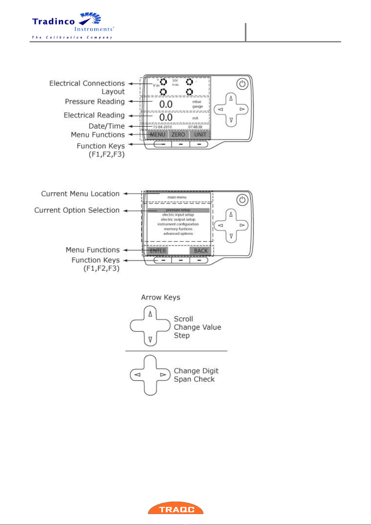
1.5 Indicator Interface
User Manual
TRAQC-9
TRAQC-9 04/2017 EN Rev.4 page : 9
1.6 Navigation
The menu can be accessed when the calibrator is in measuring mode (see figure).
Navigating through the menu is possible by pressing the function keys (F1, F2 and F3) and the
‘ARROW’ keys. Above the function keys in the display, the meaning of the function keys is
indicated. By pressing one of the function keys below the display, the menu opens.
By pressing the ‘BACK’ key (F3) results in going one level back.
The menu consists of multiple options to choose from. The option in the black bar is the one
selected. By pressing the navigation keys up or down, another option in the menu can be
selected.

User Manual
TRAQC-9
TRAQC-9 04/2017 EN Rev.4 page : 10
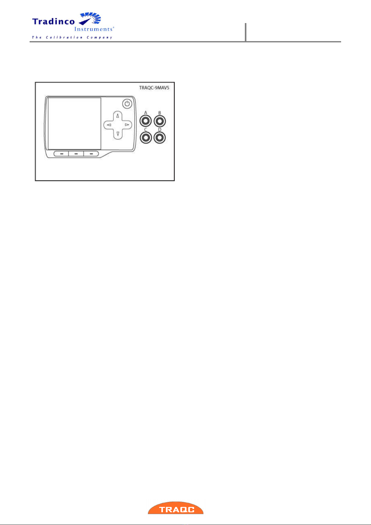
1.7 Electrical Connections
The “Electric Connections Layout” in the display references
the physical layout of these 4 banana socket. (Example see
figure).
The letters A,B,C and D are for identification purposes and
will be of reference, in this manual only.
User Manual
TRAQC-9
TRAQC-9 04/2017 EN Rev.4 page : 11
2.TRAQC-9 Types
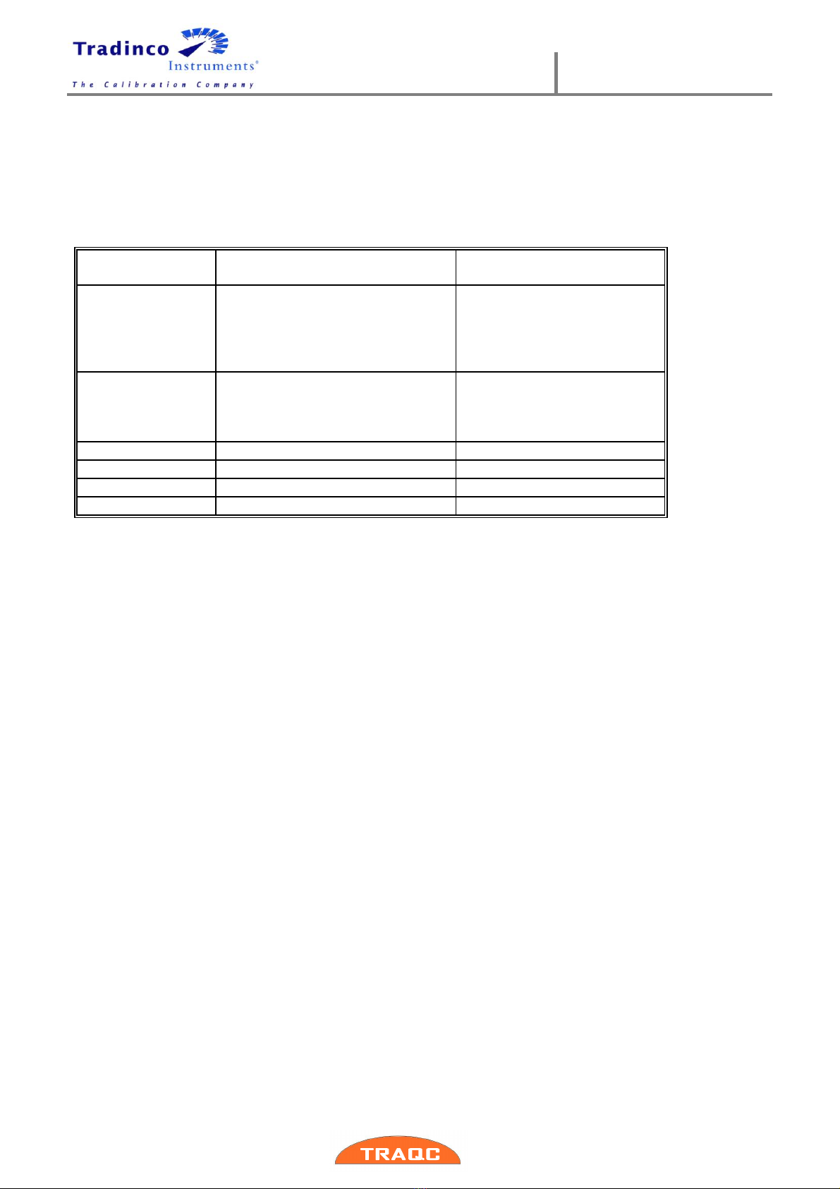
2.1 TRAQC-9 Configurations
These are:
Model
Pneumatic version
Range
TRAQC-9 P
No regulation
-1 - 1000 barg
DC Volt measurement:
0 –30 V
DC Ampere measurement:
0 –24 mA.
TRAQC-9 MAVS
No regulation
DC Volt measurement:
0 –30 V
DC Ampere measurement:
0 –24 mA
TRAQC-9 CAC
Reducer and Needle valve
0 - 10 bara
TRAQC-9 CPC
Reducer and Volume regulator
0 - 10 barg
TRRAQ-9 CLPC
Pump with volume control
0 - 1000 mbarg
TRAQC-9 CHPC
Reducer with needle valve.
0 - 350 barg
The various versions and their operating instructions are described on the following pages.

User Manual
TRAQC-9
TRAQC-9 04/2017 EN Rev.4 page : 12
2.2 TRAQC-9 P Pressure
The TRAQC-9 P is the pressure indicator.
User Manual
TRAQC-9
TRAQC-9 04/2017 EN Rev.4 page : 13
2.3 TRAQC-9 MAVS Milliamp ere and Volt Signals
The TRAQC-9 MAVS is the electrical calibrator for the TRAQC-9 series.

User Manual
TRAQC-9
TRAQC-9 04/2017 EN Rev.4 page : 14
2.4 TRAQC-9 CAC Absolute pressure Controller
The TRAQC-9 CAC absolute pressure controller, ranging 0 to 10 bar absolute depending on the
range of the selected reducer and is suitable for a so-called "dead end" system.
The calibrator is equipped with three fine regulating needle valves and a Polyflo test coupling.
The TRAQC-9 CAC has to be connected externally to a vacuum-and a pressure supply.
2.4.1 TRAQC-9 CAC operating instructions:
Connect the “test” coupling to the unit to be calibrated.
Connect the “gauge” coupling to the TRACQ-9 P.
Close the “bleed valve”(1) and the “pressure shut off valve”(2). Slowly open the “vacuum shut
of valve” (3) to the maximum admissible pressure for the "unit under test". Then close the
“vacuum shut off valve” again.
While the system is under vacuum pressure, check with the TRAQC-9 P if there is any leakage;
this becomes apparent by an extreme change of pressure.
Let air into the system by opening the “bleed valve” (1), then close the “bleed valve” (1).
Eliminate any leaks and repeat the test as described above until all leaks are eliminated.
-To generate sub barometric pressures, close the “pressure shut off valve” (2), slowly open the
“vacuum shut off valve” (3) wile observing the indicated pressure. Once the “vacuum shut off
valve” (3) is open, further regulate the vacuum pressure with the “bleed valve”(1) until the
correct pressure is obtained.
-To generate a test pressure above the barometric pressure, close the “vacuum shut off
valve”(3), open the “pressure shut off valve”(2) and regulate with the “reducer” until the desired
test pressure is obtained.
If the test pressure is to be decreased towards the barometric pressure, the “bleed valve” (1)
has to be slowly opened until the correct test pressure is reached.
Repeat the procedure as often as a new test pressure is desired.
When all test pressures have been generated, open the “bleed valve” (1), close the “vacuum
shut off valve”(2) and/or “pressure shut off valve”(3) and disconnect the test hoses.
The installed needle valves have a soft seat. It is not necessary to close these with a
great deal of force.
1
2
3
User Manual
TRAQC-9
TRAQC-9 04/2017 EN Rev.4 page : 15
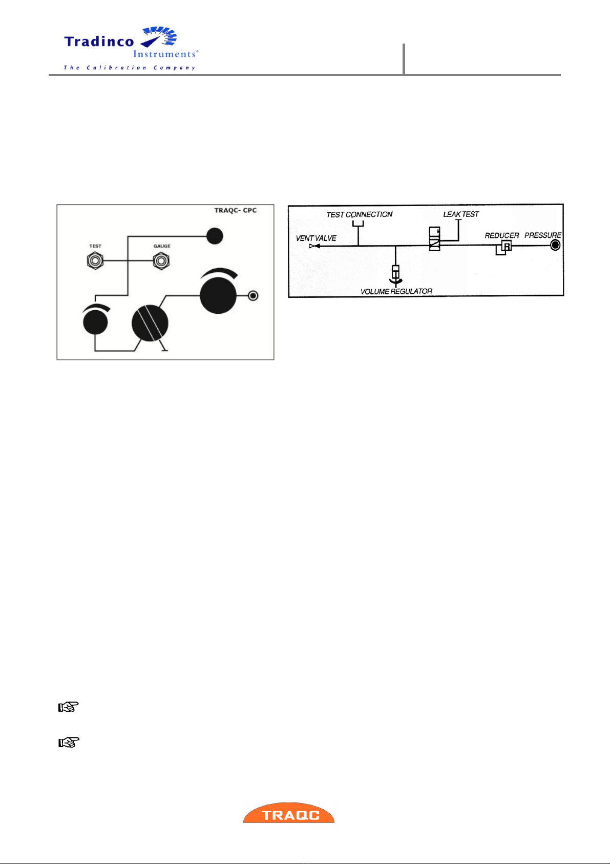
2.5 TRAQC-9 CPC Pneumatic Controller
The TRAQC-9 CPC is a pressure controller, ranging from 0 to 10 bar depending on the range of
the selected reducer and is suitable for a so-called "dead end" system.
The controller is equipped with a fine regulating reducer. The reducer has to be fed from an
external pneumatic pressure supply with a maximum pressure of 10 bar.
A leakage-free pneumatic switch is intergraded in the controller in order to be able to perform
leakage tests. Also a volume regulator has been installed for fine regulating the test pressure.
2.5.1 TRAQC-9 CPC operating instructions:
Decrease the “reducer”(4) by turning it fully counterclockwise so that the test pressure is zero,
set the “volume regulator”(2) in the middle position and close the “bleed valve”(1).
Connect the “TEST” coupling to the unit to be calibrated.
Connect “GAUGE” coupling to the TRAQC-9 P.
Open the “selector switch”(3) (knob in line).
Slowly increase the pressure by operating the “reducer”(4) clockwise, until the maximum
admissible pressure for the unit under test is reached. Close the “selector switch”(3).
Check with the TRAQC-9 P if there is any leakage, this becomes apparent by an extreme change
of the test pressure. Open the selector switch. Remove the pressure from the system by
decreasing the “reducer”(4) to minimum and by opening the “bleed valve”(1).
Eliminate any leaks and repeat the test as described above until all leaks are eliminated.
Close the “bleed valve”. Slowly increase pressure with the “reducer”(4) until the desired test
pressure has been reached; close the “selector switch”(3) and fine tune the test pressure with
the “volume regulator”(2).
The first test pressure has now been generated. After the measurement value has now been
recorded, the selector switch has to be opened again and the following test pressure can be
created.
Repeat the procedure as often as a new test pressure is desired. When all test pressures have
been generated, the selector switch must be opened, the “reducer”(4) must decreased set to
minimum (fully ccw),open the “bleed valve”(1), the test hoses must be disconnected and turn in
“volume regulator”(2) completely.
It is recommended to regulate the decrease of the test pressure by means of the “bleed
valve”(1) instead of the reducer; this avoids fouling of the reducer
The installed needle valve has a soft seat. It is not necessary to close these with a great
deal of force.
1
4
3
2
1
User Manual
TRAQC-9
TRAQC-9 12/2011 EN Rev.1 page : 16
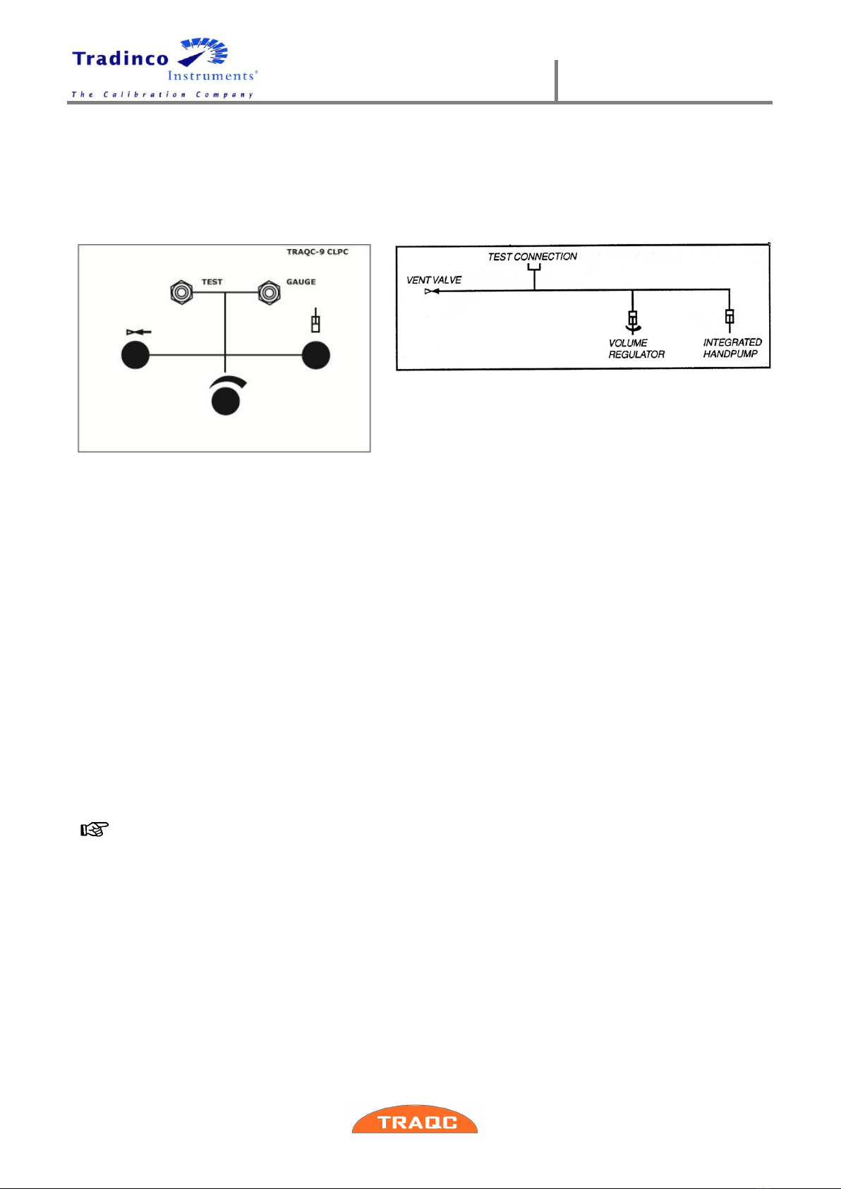
2.6 TRAQC-9 CLPC Low Pressure Controller
The TRAQC-9 CLPC is a low pressure controller, ranging from 0 to 1000 mbar and is suitable for
a so-called "dead end" system.
Integrated in the controller are a small manually operated pump and a volume regulator for
generating and regulating the test pressure.
The TRAQC-9 CLPC needs no external pneumatic supply.
2.6.1 The TRAQC-9 CLPC operating instructions:
Connect the “TEST” coupling to the unit to be calibrated.
Connect the “GAUGE” coupling to the TRAQC-9 P.
Close the “bleed valve” (1). Use the “manual pump”(3) to create the maximum admissible
pressure for the "unit under test".
Check with the TRAQC-9 P if there is any leakage, this becomes apparent by an extreme change
of the test pressure. Release air from the system by opening the “bleed valve” (1). Set the
“volume regulator”(2) in the middle position.
Eliminate any leaks and repeat the test as described above until all leaks are eliminated.
Close the “bleed valve” (1). Use the “manual pump” (3) to get close to the desired test
pressure. Now use the “volume regulator” (3) to fine trim the test pressure to the desired value.
Repeat the procedure as often as a new test pressure is desired. When all test pressures have
been generated, open the “bleed valve” (1), disconnect the test hoses and turn in the “volume
regulator” (2) completely.
The installed needle valve has a soft seat. It is not necessary to close this with a great
deal of force.
3
1
2

User Manual
TRAQC-9
TRAQC-9 04/2017 EN Rev.4 page : 17
2.7 TRAQC-9 CHPC High Pressure Controller
The TRAQC-9 CHPC is a high pressure controller, ranging from 0 to 350 bar, depending on the
range of the selected reducer and is suitable for a so-called "dead end" system.
The calibrator is equipped with a high pressure reducer. The reducer has to be fed from an
external high pressure supply with a maximum pressure of 350 bar.
2.7.1 TRAQC-9 CHPC Operating instructions:
Decease the “reducer”(3) to minimum by turning it fully counterclockwise.
Close the “pressure shut off valve”(2) by turning it fully clockwise.
Connect the “test” coupling to the unit to be calibrated.
Connect the “Gauge” coupling to the TRAQC-9 P.
Close the “bleed valve”(1) and open the “pressure shut off valve”(2). Slowly increase the
pressure with the “reducer”(3) until the maximum admissible pressure for the unit under test is
reached. Close the “pressure shut off valve”(2) and decrease the “reducer”(3) to minimum.
Check with the TRAQC-9 P if there is any leakage; this becomes apparent by an extreme
change of the test pressure. Then remove the pressure from the system by opening the “bleed
valve”(1).
Eliminate any leaks and repeat the test as described above until all leaks are eliminated.
Close the “bleed valve”(1). Open the “pressure shut off valve”(2) and increase the “reducer”(3)
to approximately 110% of the desired test pressure. Than close the “pressure shut off
valve”(2).
For regulating the test pressure:
-Slowly opening and closing the “pressure shut off valve”(2) will result in a pressure increase.
-Slowly opening and closing the “bleed valve”will result in a pressure decrease.
A measurement can be performed when both the “pressure shut off valve”(2) and the “bleed
valve”(1) are closed.
Repeat the procedure as often as a new test pressure is desired. When all test pressures have
been generated, decrease the “reducer”(3) to a minimum, close the “pressure shut off
valve”(2), open the “bleed valve” (1) and disconnect the test hoses.
The installed needle valves have a soft seat. It is not necessary to close these with a
great deal of force.
3
2
1

User Manual
TRAQC-9
TRAQC-9 04/2017 EN Rev.4 page : 18
2.8 TRAQC-9 CVC
The TRAQC-9 CVC vacuum pressure controller, ranging -1 to 0 bar gauge and is suitable for a
so-called "dead end" system.
The calibrator is equipped with two fine regulating needle valves and a Polyflo test couplings.
The TRAQC-9 CAC has to be connected externally to a vacuum supply.
2.8.1 TRAQC-9 CVC operating instructions:
Connect the “test” coupling to the unit to be calibrated.
Connect the “gauge” coupling to the TRACQ-9 P.
Close the “vacuum shut off valve” (2) and then the “bleed valve” (1). Slowly open the “vacuum
shut of valve” (2) to the maximum admissible vacuum pressure for the "unit under test". Then
close the “vacuum shut off valve” (2) again.
While the system is under vacuum pressure, check with the TRAQC-9 P if there is any leakage;
this becomes apparent by an extreme change of pressure.
Let air into the system by opening the “bleed valve” (1).
Eliminate any leaks and repeat the test as described above until all leaks are eliminated.
-To generate vacuum pressures, close the “vacuum shut off valve” (2) and then “bleed valve”(1),
slowly open the “vacuum shut off valve” (2) wile observing the indicated pressure. Once the
“vacuum shut off valve” (2) is open, further regulate the vacuum pressure with the “bleed
valve”(1) until the correct pressure is obtained.
Repeat the procedure as often as a new test pressure is desired.
When all test pressures have been generated, open the “bleed valve” (1), close the “vacuum
shut off valve”(2) and disconnect the test hoses.
The installed needle valves have a soft seat. It is not necessary to close these with a
great deal of force.
1
2
User Manual
TRAQC-9
TRAQC-9 04/2017 EN Rev.4 page : 19
3.Operating Instructions
3.1 Power On/Off
The TRAQC-9 is switched on and off by pressing the on/off key. The TRAQC-9 will go through a
short startup self-check routine. During that routine the display shows the current firmware.
After completing the startup procedures the device switches into the measuring mode and
displays the measured value(s), and the measuring unit(s) from last time. When turning off the
device, the display shows ‘Shutting Down’.
If the calibrator needs to be recalibrated at short notice, a message with the date that the
instrument should be re-calibrated is displayed for several seconds before the startup
procedure continues. If the recalibration date has expired a message is displayed as a
warning. By pressing ‘ENTER’ key (F1) the start-up procedure is continued.
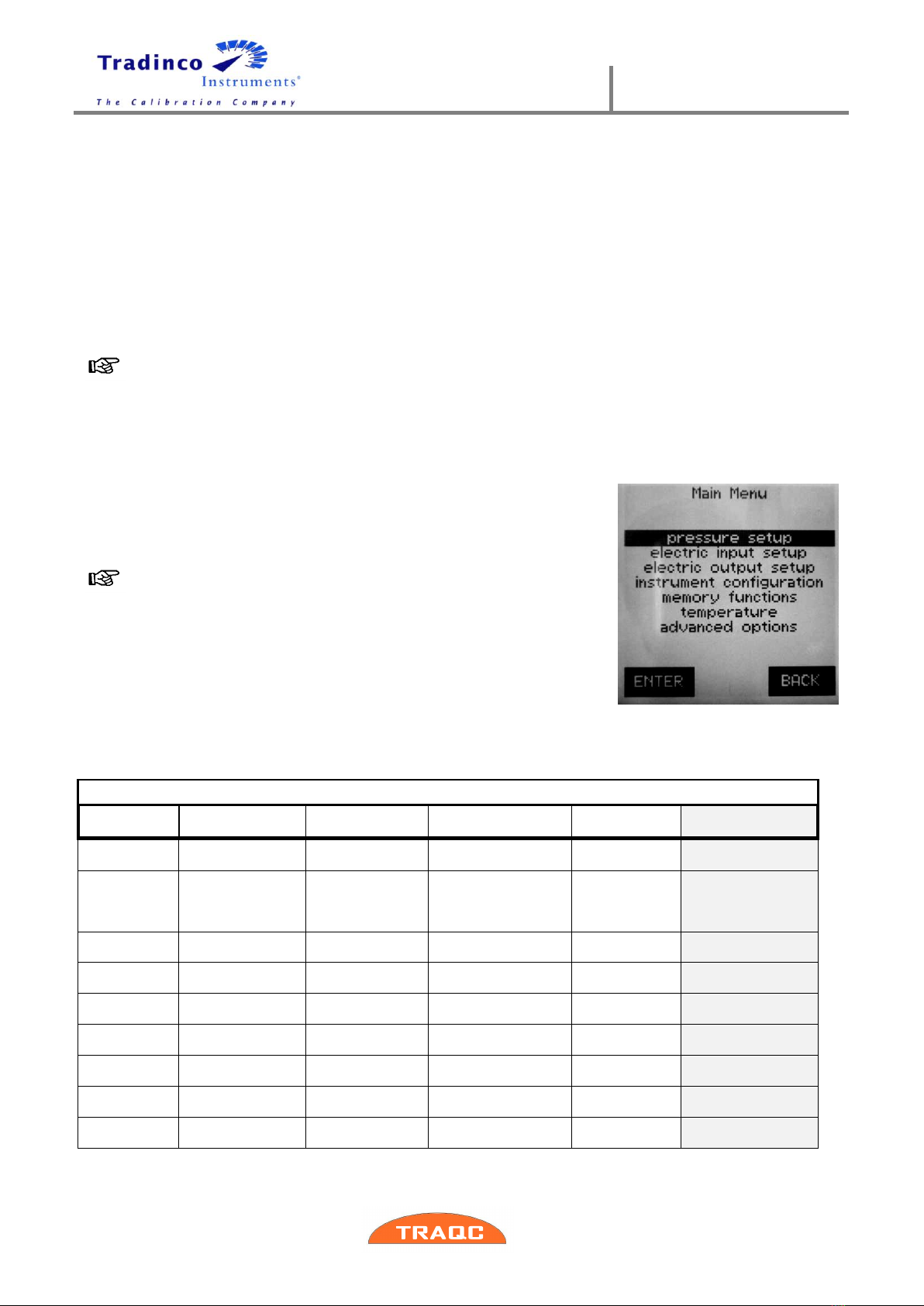
3.2 Menu
The main menu is accessed by pressing the ‘MENU’ key (F1). On
top in the display the current location in the menu structure is
shown.
Most of the functions in the menu structure are optional.
Therefore it is possible the TRAQC-9 included with this
manual has less functions than explained in this user
manual.
3.2.1 Main Menu Structure
Main Menu
pressure
setup
electric input
setup
electric output
setup
instrument
configuration
memory
functions
advanced options
averaging
on/off
mA input
pressure xmtr
mode
backlight setup
list by tagnr.
Set rtc time
averaging
setup
mA + Xmtr supply
xmtr mode
settings
select language
list by serialnr.
Set rtc date
resolution
setup
Xmtr power setup
current output
date/time display
view definitions
Set recall date
conversion
table
switch test
current output
settings
show settings
Erase data memory
Set customer
unit
switch test setup
voltage output
factory defaults
Show instrument
data
gauge mode
V input
voltage output
settings
Adjust instrument
inputs
absolute
mode
Hart resistor
auto span check
mode
Adjust instrument
output
set abs
interval
mA/V scaling
ramp mode
Show calibration
factors
set
Baro.ref.int
set mA/V scaling

User Manual
TRAQC-9
TRAQC-9 04/2017 EN Rev.4 page : 20
3.3 Zeroing
To zero an input signal press ‘ZERO’ key (F2) in the “measuring
mode” display. The menu shows the different inputs that can be
zeroed, consisting of pressure inputs and the electrical inputs.
Select the desired input using the ‘ARROW’ keys.
By pressing the ‘BACK’ key (F3) the zeroing procedure is
stopped without making modifications.
By pressing ‘ENTER’ key (F1) the zeroing procedure is
continued and there is asked to confirm the zeroing
procedure after which the calibrator returns to measuring
mode.
When zeroing the ‘Pressure Input’, ensure that the
pressure ports are open to atmospheric pressure.
The TRAQC-9 P comes standard with a quick connect coupling with
integraded shut off valve. This can be opened by:
Connect/insert the other half of the coupling to the
pressure coupling (-port) of the TRAQC-9 P
Connect one side of a pressure hose to the pressure
coupling (-port) of the TRAQC-9 P and leave the other side
of the hose unconnected.
With these procedures the pressure in the system of the
TRAQC-9 P can get equal with the atmospheric pressure.
To zero another test pressure and/or electrical signal, first generate the required test signal
(tare value) and carry out the above-described zeroing procedure. The test value displayed is
the difference between the actual test value and the entered tare value.
3.4 Selecting Pressure Units
When in “measuring mode”screen press the ‘UNIT’ key (F3) to
change the unit. Use the ‘ARROW’ keys to select the desired unit
and press ‘ENTER’ key (F1) to confirm and go back to “measuring
mode”.
The following units can be selected:
bar kgf/cm2inHg
mbar mmH2O torr
Pa cmH20 %
hPa mH2O mSeaw
kPa inH20
MPa ftH2O
psi mmHg
This manual suits for next models
6
Table of contents
Other Tradinco Test Equipment manuals


