Soil-Max Gold Digger Stealth ZD User manual

Drainage Plow Manual
Soil-Max, Inc.
Precise, Progressive, Great Service
888-Soilmax (764-5629)

Warning !!!!
Before using the Gold Digger drainage plow, call (888) 258-0808 (the toll-free
national call before you dig number). You need to have a determination made as
to whether or not any underground gas lines, electrical lines, fiber optic or normal
phone lines, or any other underground object or condition exist in the area you
will be running the plow. Have these thoroughly marked and maintain the
recommended distance from these areas.
Soil-Max is not liable for any damages or injury which may result from contact
with any above ground or underground object.
CALL (888) 258-0808
BEFORE YOU DIG!!
Page 2

Soil-Max Gold Digger Stealth ZD
“How-To” Guide
Thank you for purchasing the Soil-Max Gold Digger Stealth ZD. We know it is one of the most important
tools you will ever have on the farm. Our purpose is to develop equipment that will make farmers
profitable.
This “ How-to ” guide will explain the function and use of the Gold Digger. If you have any questions
about any Soil-Max equipment, or the use of this equipment for installation of field tile, please call our
office, toll free at (888) 764-5629 and we will be glad to discuss this with you.
Gold Digger Applications:
1. Add tile to already existing tile systems.
2. Random tiling systems, low draws, hillside seeps, etc.
3. New tile systems.
4. Installation of water lines, cables, etc.
5. Installing sub irrigation lines or tile for orchards, vineyards, high-cash crops and greenhouses.
Page 3

Table of Contents
Plow “Parts Identification”
5
Serial Number Identification
8
“Which Tractor” to Use
9
3pt Plow Hookup and Geometry
10
Toplink Cylinder
11
Draft Control/Quick Hitch
12
Hydrualic Hoses/Connections
12
Waterlevel
13
Pull-Type Plow Operation
13
Drawbar Placement
13
Down Pressure Manifold Electrical Schematics
15
Boot Removal
16
Shear Wear
16
Tile Feeder
17
Automatic Grade Control Hydraulic Schematics
17
Manual Grade Control Hydraulic Schematics
18
Electronics Hookup
19
TopCon Laser System Initial Setup
21
Apache Laser System Initial Setup
24
First Time “Using the Gold Digger in the Field
29
Incorporating s Second Pull Tractor
29
Pre Ripping
29
Manual Grade Control
30
Automatic Grade Control
30
Designing Tile Systems
31
Tile Size in Acres Drained Reference Chart
32
Using a Laser-Determining Grade & Coverage
33
Formulas for “Tile Grade Situations”
35
Frequently Asked Questions
36
Index
37
Page 4
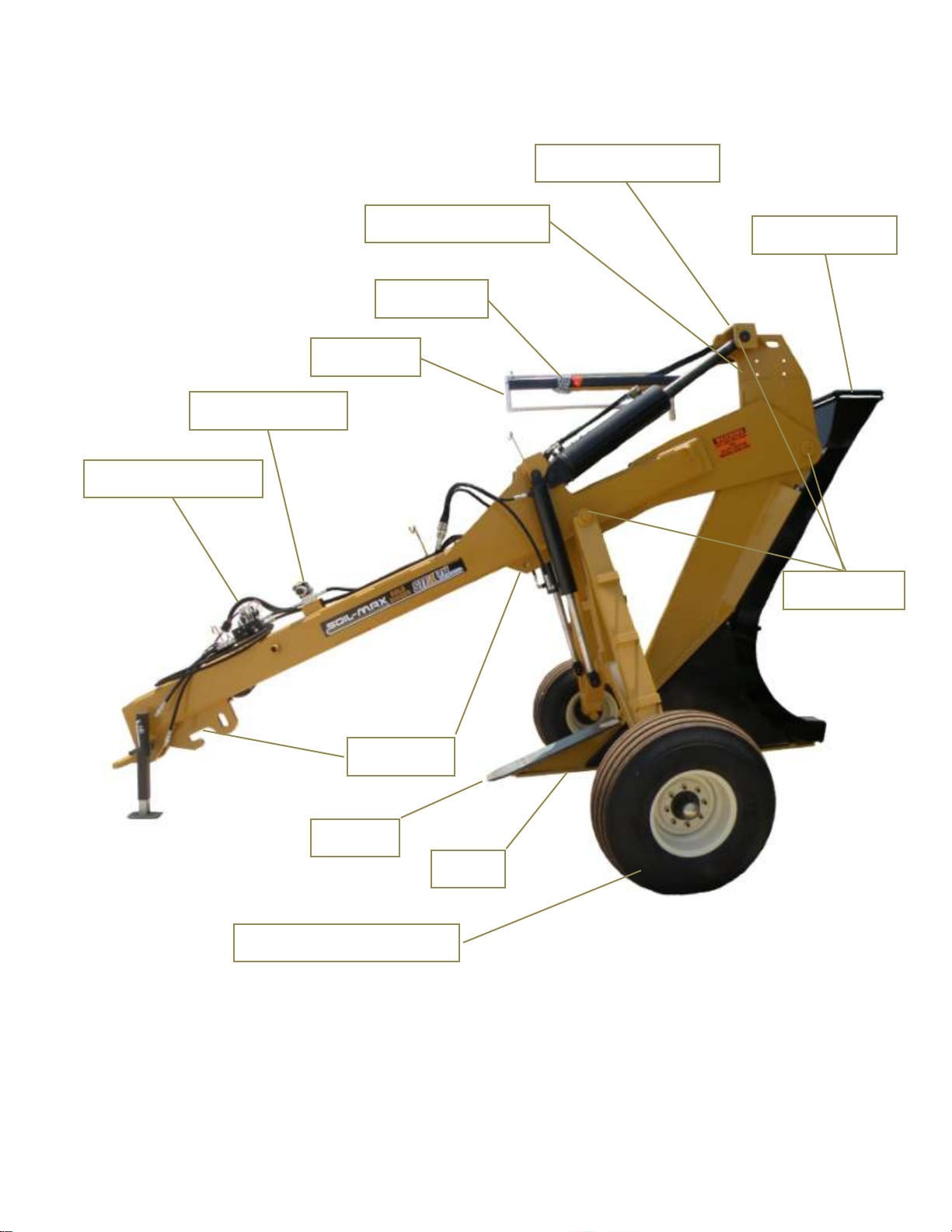
Pull Type Parts Identification
Page 5
Water Level
Tile Boot Rollers
Walking Tandems (Optional)
GPS Arm Mount
Heel
Pull Hook
Grease Daily
Depth Chain
Proportional Valve
Downpressure Valve
Shear
Power Feeder Mount

3 Point Parts Identification
Page 6
Depth Chain
Water Level
7” Cylinders
6” Top Link Cylinder
erer
Proportional Valve
Owner’s Manual Storage
Top Link Tower
3pt Stands
Shear
Heel
Boot Funnel
Power Feeder Mont
GPS Arm Mount
Mount
Funnel Rollers

Hydraulic Valve Parts Identification
Down-Pressure Manifold Proportional Control Valve
(Controls Plow Wheels) (Controls Plow Shank Pitch)
See Index for Valve Schematic Diagrams
Page 7

Serial Number Identification
The serial number will contain the plow number, date of
manufacture and model information.
You want to use the serial number for insurance purposes.
My Serial Number: _______________________________________________________
Page 8
Serial Number
Plow Number

Tractor Selection
The first decision to make before attaching the plow to a tractor is “which tractor do I use?” It is not
necessarily true that the largest horsepower-rated tractor you have will work the best. You must take
into consideration the weight of the tractor, how good the tires are, what type of tire (radial or bias) and
the height of the tires. Keep in mind that a lower horsepower-rated tractor properly weighted may be
able to do the job to your satisfaction. Generally, a tractor weighing at least 20,000 lbs. can pull the
plow 3 to 3 ½ feet deep in good soil conditions.
If you are using the plow in good, dry soil conditions, it may be best to pull the plow without duals on the
tractor. This will allow all of the weight of the tractor to be transferred to a smaller surface area.
However, in less than ideal conditions, where the surface of the ground is slick or sticky, duals may
enhance traction. We do not recommend pulling the plow in very muddy conditions as this will probably
make your tiling job very frustrating and may cause compaction problems.
The charts below will give you an idea of what tractor to choose based on the depth you want to pull.
The depths are based on a 4 in boot. Every boot size increase such as 4 in to 6 in will reduce these
numbers by 20% roughly.
Page 9
Typical Tile Plow Depths
4in Boot (Normal Conditions)
Tractor Weight
(Lbs.)
Plow Depth 1
Pass
Plow Depth 2
Pass
20,000 –30,000
3.5 to 4 ft
4 to 4.5 feet
30,000 –40,000
4.0 to 5 feet
5 to 6 feet
40,000 +
5.0 to 6 feet
6.0 to 7 feet
Depth Factors
Rating
Comments
Radial Tires
Increase 5%
Tall 42" or 46" Tires
Increase 10%
Tall Helps
Tire Pressure
Increase 5%
Keep Under 15
lbs
Tire Lug Type
Increase 5%
We like big Lugs!

3-Point ZD Plow Hookup and Geometry
The 3-point comes equipped for Category III attachment. Attachment to a Category IV 3-Point hitch
is possible with the use of CAT III to CAT IV bushings. All pins and hardware should come with the
plow.
Adjusting the top link is very important. Attach your top link to the bottom or lowest hole on your
tractor and the highest hole you can reach on the plow. The ideal appearance of the 3 point arms
should look like the illustrations below. The 3pt arms should be evenly aligned with the plow frame.
The arms should not down into a “V” with the plow frame because this will place too much pressure on
the top link and it may break.
CORRECT
INCORRECT
Page 10

Please use the top hole on the plow for attaching the top link if possible. However, be careful when
lifting the plow the first time. On some tractors top link housing is directly beloow the stakc of
hydraulic couplings and may hit part of the tractor when the plow is raised. Spacer blocks are available
for John Deere 30 through 60 series tractors that may have this issue. The spacers extend the top
link out 3” farther from the tractor.
The top link must be adjusted so that the shoe of the plow does not drag the ground when the plow is
lifted. However, it is important that the bottom of the shoe is not any higher than 12 inches from
the ground when the plow is completely lifted.
You may also need to adjust the top link when you drop the plow into the first tiling run if the 3 point
arms do not allow it to go deep enough. You will want to make sure the two lower arms are locked so
that they do not float within the lift arm.
Toplink Cylinder
The Gold Digger ZD 3 point plow is equipped
with a hydraulic cylinder on the top link of the
three point hitch. The purpose of this cylinder
is to simply extend the geometry of the plow to
allow the maximum depth of the plow.
The correct position of this cylinder is to keep
the 3 point tower at a 90 degree angle to the
frame of the plow.
Draft Control Settings
The 3-point hitch will need its draft control turned completely off.
The 3-point hitch needs to float for the plow to work properly.
For most tractors this adjustment is made with only a knob or
lever. Refer to your tractor’s owner’s manual or dealer for
instructions. For some, however, there may be pins that will
need to be removed or changed for the draft to be turned off.
Some tractors with electronic controls require the 3 point hitch
to be cycled to complete the process after every start up of the
tractor. Check your owner’s manual for instructions.
Quick Hitch
WARNING!
DO NOT Use a Quick Hitch with the Gold Digger ZD 3-
Point Hitch Model Tile Plow. The geometry needed for
the plow to be lifted out of the ground and go down far
enough to reach the plow’s potential is not achievable
with a quick hitch Page 11

Hydraulic Hoses
The plow will come standard with pioneer hydraulic fittings. You will only need one set of hydraulic
outlets if a plow control system such as laser or GPS is used. A separate outlet will be needed for the
optional tile feeder. Make sure you connect to the tractor’s primary hydraulic remote. This
remote will need to have its hydraulic flow (speed) turned up all the way if possible.
Hydraulic fluid direction is important. In the front of each of the valve bodies is the letters “P” and “T”.
“P” is for Pressure and “T” is for Tank. Note: If the fluid is in the wrong direction, the valves will not
work correctly.
Hydraulic Connections
Tie up all hydraulic hoses and take care to remove any dirt from tractor remote connections and
pioneer fittings prior to connection with tractor remotes. Valve tolerances are very tight and
debris can cause malfunction of valves.
Page 12

Water Level
Once you have the plow attached, lower it on a flat surface. Lay a level alongside the shoe and read
the bubble. Now fill the water level with anti-freeze to the thick graduation where the red and green
graduated marks meet. This mark represents the shoe being level (0% slope). You will need to check
this again in one hour or so as the baffle in the water level may soak up some amount of anti-freeze.
NOTE: Water level is shipped upside down to guard against damage during transport. The level must
be turned upright for filling and use.
Shipping Position Operation Position with Fluid
Pull-Type Plow Operation
Drawbar Placement
When attaching a Gold Digger Stealth ZD Pull-Type plow to your tractor’s drawbar, please be sure that
the drawbar is pulled in as close to the tractor as possible to avoid breaking or damaging the drawbar.
This is especially important on smaller front wheel assist tractors.
Page 13
Hydraulic Detente
The wheels will not operate correctly if the tractor remote is detented (engaged) in the wrong
direction. The down-pressure valve has TANK and PUMP marked on the ports in the front of the valve.
The hose connected to the PUMP port should be stiff with pressure when detented (engaged) correctly.
Hydraulic Flow Only Goes One Way
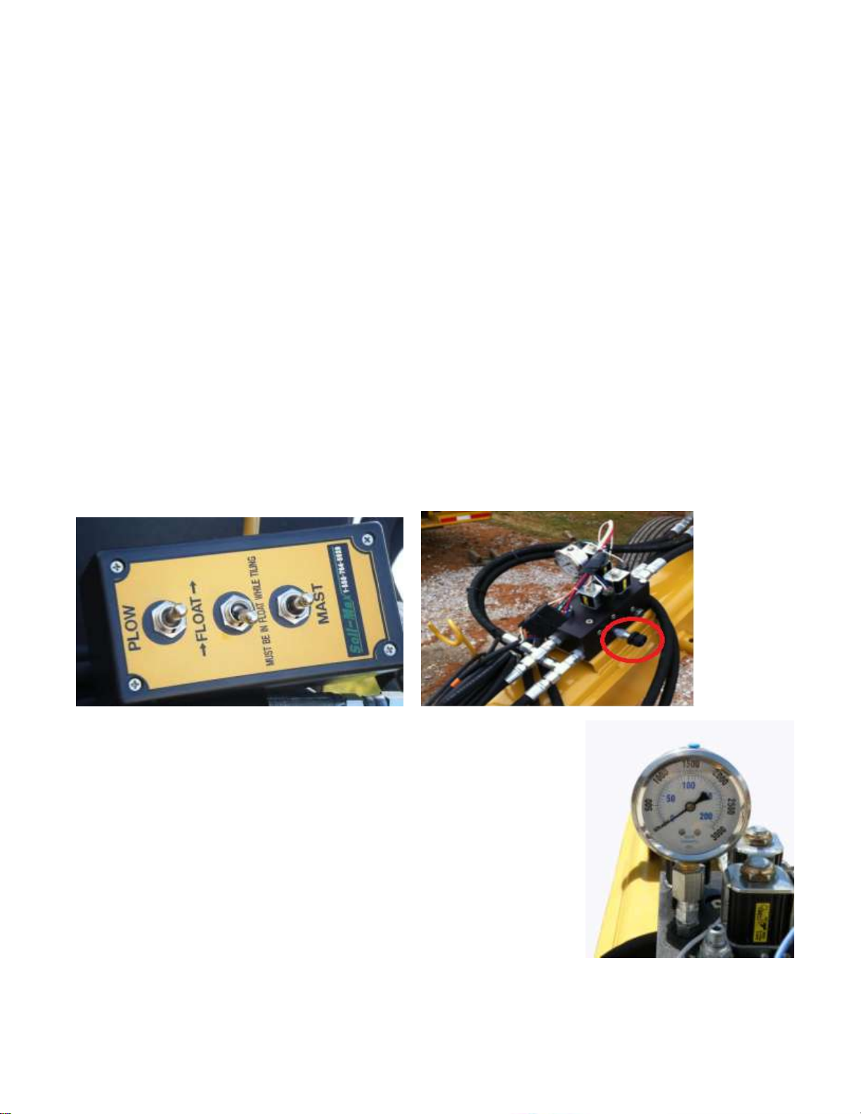
Switchbox Instructions
The instructions in this section pertain to how you operate the wheels on a pull-type Gold Digger plow.
The wheels are operated by the black switchbox with either 2 or 3 switches. One switch is to move a
laser mast which would not pertain to you if you have an Intellislope or manual plow.
The switch marked “PLOW” operates the wheels. In the operation of tiling this switch is only used to
lower the plow into the start and pick the plow up after it has been steered to the top of the ground with
the 6” grade control cylinders. In other words, the plow must be brought to the surface of the ground by
pitching it UP with the 6” cylinders BEFORE it can be raised up off the ground with the wheels.
The “float” switch lowers the hydraulic pressure to the tires to around 200 psi. If you have more than
200 pounds of pressure, turn the round knob on the left side of the down-pressure block as shown in
the illustration counterclockwise to lower pressure. The float switch must be on to adjust the pressure. If
you need more pressure on the wheels turn the round knob clockwise. The plow must have enough
pressure to provide vertical stability for the plow, without so much pressure that the tires pull the plow
off grade when going over humps.
Normal Sequence of Operating the Wheels
1. With float mode off, lower plow into start with plow switch, Hold
plow on tires until movement begins.
2. As plow starts forward into soil, pull the shear into the soil about
2 feet, then turn on the float switch, pressure gauge should drop
to 200 psi.
3. Install tile with float switch on
4. When done installing, pitch the plow up with the large 7”
cylinders on top
5. Pull forward 8 to 10 feet.
6. Turn Float Switch off and raise the plow with the PLOW switch.
7. Warning!!! DO NOT use the plow switch to try to lift plow
when in the ground! Plow warranty is void when damage
occurs from plow being lifted out of ground by the wheels
and not by pitching the plow up and pulling the plow forward to the top of the ground
Page 14

Down Pressure Manifold
Electrical Schematics
Note: The position of the wires to the solenoids on the Down Pressure Manifold is very
important. With incorrect wire placement, malfunction of the manifold will occur and potential
injury. Please take care when removing, cleaning, or replacing wire connections.
Page 15

Boot Removal
Often during the course of an installation, different
boot sizes will be needed. Changing the boot is
easily done. First remove the fastener marked 1
and remove the funnel. Remove fastener marked
2 and the bottom portion of the boot will come off
in two pieces. Note the alignment pins on the
heel of the plow . Each size of boot has a
corresponding shear. Remove and replace with
the proper size shear.
Installation is the reverse of removal.
Shear Wear
Over time, the shear will wear on the cutting edge. How to gauge wear is shown in the illustration
below. Place a straight edge on the bottom of the cutting edge of the plow. The gap between the
shear and the heel will be about 3/8” when new. When the cutting edge of the shear is even with the
heel, the shear must be replaced.
Lack of replacement will cause the heel to wear excessively.
When the shear tip is even with the heel, the plow may try to come up and grade control will be
deteriorated.
Page 16
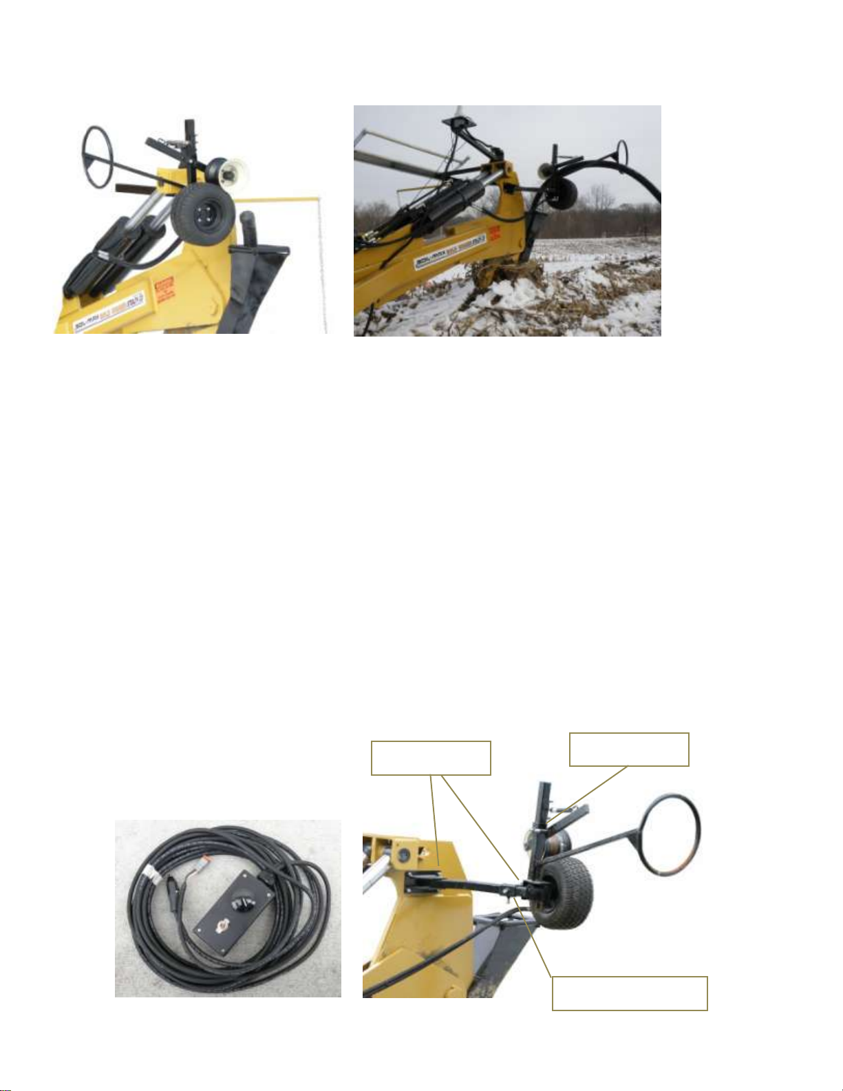
Tile Feeder (Optional)
The optional tile feeder is a great addition to any plow. It is not required but is a great reassurance of
tile quality. The tile feeder simply pushes on the tile to ensure no stretch is occurring.
Hydraulic fluid direction is important to correct operation. Take note of the direction the wheel turns;
the wheel should turn toward the plow. If reverse direction, change the direction of the fluid
detent. The hydraulic flow to the feeder should be slowed to reduce torque. When the plow
stops, the feeder should stop. The feeder is for assistance only not to rub and harm tile.
Start hydraulic flow very slowly ( 8 gpm or less ) and gradually increase. Flow too high will not allow tile
speed to be regulated with the rheostat switch.
If it’s not possible to adjust or slow the hydraulic flow, user should be ready to change the switch from
“on to “off” to stop the feeder. See the picture below of the control box. Turn the dial to adjust the
speed and move the switch for on/off of the feeder.
The tile feeder mounting brackets have three adjustments shown in the illustration below. Adjust the
feeder spring tension to give just enough tension on the spring to keep the tile in the wheel without the
tire. The hinge points of the tile feeder should be adjusted to align tile with funnel for an easy entry into
the funnel. Once adjusted, tighten to restrict moement.
Page 17
Hinge Points
Funnel Alignment
Spring Tension

Automatic Grade Control Plow Hydraulic Schematics
“T” Stands for “TANK”. This is the port through which oil returns to the reservoir.
“P” Stands for “PRESSURE” or “PUMP”. This is the port thorough which pressurized oil is sent to the
plow.
Page 18

Manual Grade Control Plow Hydraulic Schematics
“T” Stands for “TANK”. This is the port through which oil returns to the reservoir.
“P” Stands for “PRESSURE” or “PUMP”. This is the port thorough which pressurized oil is sent to the
plow.
Page 19

Electronics Hookup
Intellislope GPS Control System:
If you purchased the Intellislope GPS plow control system please refer to that systems manual for this
section. To learn more about the Intellislope you can visit: www.intellislope.com or call us toll free at:
888-SOILMAX and select Sales (option one).
Laser Guided Control System: (Also see Schematics following this page)
If you have purchased an automatic laser system, the electro-hydraulic valve mounts on the plow’s
frame below the top link attachment. This valve is hooked to the electronic control box to be put in the
tractor cab. It controls the hydraulic cylinders on the plow for automatic (using a laser) or manual
control of the shoe depth incrementally. The control box can be mounted in the tractor and needs 12
volt power supplied to it. There are two main cables to connect.
1. Connect the laser receiver cable to the receiver first.
2. Then connect the other end of the receiver cable to the control box in the cab.
3. Now connect the other cable to the control box and to the electro-hydraulic valve on the plow.
4. You will also have to connect the 12 volt power to the appropriate cable.
If you make the connections in this order, you will avoid any errors. You can, however, get the “up and
down” functions for the plow’s cylinders reversed. “Up” should extend the cylinders and “Down” should
bring them back in. If this is reversed, you may need to switch the hydraulic hoses going to the tractor
remote (they may be backwards), or just detent the hydraulic remote the other way. The valve block is
labeled where the hoses go in. One side is labeled “P” for pressure and the other side is labeled “T” for
tank. Make sure the hose that is under pressure is going into the block where it is labeled “P”. The
black and white wires (for lowering the plow) on the top of the valve should go closest to the middle of
the plow.
The laser mast should be mounted on the 3 inch tubing on the right side of the plow. It should be
mounted directly above the front of the plow shear. There will be a switch box which will need 12 volt
power to run the mast up and down. When traveling across field, lower the laser receiver to the
bottom of the mast to avoid damage. Traveling at high speeds may damage laser masts and
electronic sensors, please use discretion.
Page 20
Table of contents
Popular Farm Equipment manuals by other brands

Slootsmid
Slootsmid SB Eco Series user manual

Amazone
Amazone Citan 12001-C operating manual

Rosensteiner
Rosensteiner Kipp Top II Basic Operating, and servicing instructions

Rain-Flo Irrigation
Rain-Flo Irrigation CHALLENGER 1800 operating manual

CrustBuster
CrustBuster 4740 owner's manual

KUHN
KUHN GMD33 N Assembly & operators manual

Land Pride
Land Pride NTS2607 Operator's manual

Wiesenfield
Wiesenfield WIBS-002 user manual

Celikel
Celikel CHARGER V Series Operator's instruction manual

Precision Manufacturing Inc.
Precision Manufacturing Inc. 662000 Operator's manual

AIRTUG
AIRTUG TT-M-EM-2 Assembly & operating instructions

COOPS & FEATHERS
COOPS & FEATHERS 223-02 Assembly instructions


