Demco TRUSS-T BOOM 21 User manual

AB20002, Rev 10
09/18
TRUSS-T BOOM
21’, 30’ & 40’

Page 2 AB20002
Thank you for purchasing a Demco spray boom. We feel you have made a wise choice and hope you are completely
satisfied with your new boom. If you have any questions regarding the applications of certain solutions or chemicals,
contact your chemical supplier and follow chemical manufacturer recommendations as well as all licensing and use
restrictions or regulations.
GENERAL INFORMATION
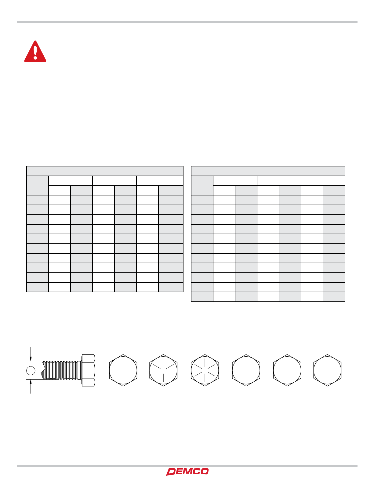
1. Unless otherwise specified, high-strength (grade5)
(3 radial-line head markings) hex head bolts are used
throughout assembly of this sprayer.
2. Whenever terms “LEFT” and “RIGHT” are used in this
manual it means from a position behind sprayer and
facing forward.
3. When placing a parts order, refer to this manual for
proper part numbers and place order by PART NO.,
DESCRIPTION, and COLOR.
WARNING: TO AVOID PERSONAL INJURY OR PROPERTY DAMAGE, OBSERVE FOL-
LOWING INSTRUCTIONS:
Chemicals are dangerous.Know exactly what you’re going to do and what is going
to happen before attempting to work with these products. Improper selection or
use can injure people, animals, plants and soil.
Always wear protective clothing such as coveralls, goggles and gloves when work-
ing with chemicals or sprayer.
Be sure to dispose of all unused chemicals or solutions in a proper and ecologically
sound manner.
Table of Contents
General information................................................................................................................... 2
Warranty Policy, Operator Manuals & Registration................................................................ 2
Safety , Signal Words ................................................................................................................. 3
Equipment Safety Guidelines ................................................................................................... 4
Lighting and Marking ................................................................................................................ 4
Safety Sign Care ......................................................................................................................... 5
Tire Safety.................................................................................................................................... 5
Remember .................................................................................................................................. 5
Before Operation ......................................................................................................................5-6
During Operation......................................................................................................................6-7
Following Operation.................................................................................................................. 7
Highway and Transport Operations........................................................................................8-9
Performing Maintenance........................................................................................................... 9
Bolt Torque................................................................................................................................. 10
Spray Tip Assembly and Installation ....................................................................................... 11
Sprayer Calibration Procedures............................................................................................... 12
Spray Tip Charts ........................................................................................................................ 13
Nozzle Parts Breakdown and List ............................................................................................ 14
21’ - 30’ Truss-T Boom Parts Breakdown and List .................................................................. 15
40’ Truss-T Boom Parts Breakdown and List........................................................................... 16
Sprayer Checklist....................................................................................................................... 17
WARRANTY POLICY, OPERATOR MANUALS, PARTS MANUALS & REGISTRATION
Go online to www.demco-products.com to review Demco warranty policies, operator manuals and register your Demco
product.
INTRODUCTION

Page 3 AB20002
SAFETY
TAKE NOTE! THIS SAFETY ALERT SYMBOL FOUND THROUGHOUT THIS
MANUAL IS USED TO CALL YOUR ATTENTION TO INSTRUCTIONS INVOLVING YOUR
PERSONAL SAFETY AND SAFETY OF OTHERS. FAILURE TO FOLLOW THESE INSTRUCTIONS
CAN RESULT IN INJURY OR DEATH!
THIS SYMBOL MEANS
ATTENTION
BECOME ALERT
YOUR SAFETY IS INVOLVED!
DANGER:
Indicates an imminently hazardous situation that, if not
avoided, will result in death or serious injury. This signal
word is to be limited to most extreme situations typically
for machine components which, for functional purposes,
cannot be guarded.
WARNING:
Indicates a potentially hazardous situation that, if not
avoided,could result in death or serious injury, and includes
hazards that are exposed when guards are removed. It may
also be used to alert against unsafe practices.
CAUTION:
Indicates a potentially hazardous situation that, if not
avoided, may result in minor or moderate injury. It may also
be used to alert against unsafe practices.
If you have questions not answered in this manual, require additional copies, or if your manual is damaged, please contact
your dealer or DEMCO, 4010 320th Street, Boyden, IA 51234
ph: (712) 725-2311 or Toll Free: 1-800-543-3626 Fax: (712) 725-2380 or 1-800-845-6420
http://www.demco-products.com
SIGNAL WORDS:
This manual uses the following signal words--DANGER,
WARNING, and CAUTION-- with safety messages. The
appropriate signal word has been selected using the
following guidelines.

Page 4 AB20002
SAFETY
SAFETY...YOU CAN LIVE WITH IT
EQUIPMENT SAFETY GUIDELINES
Every year many accidents occur which could have been avoided by a few seconds of thought and a more
careful approach to handling equipment. You, the operator, can avoid many accidents by observing the
following precautions in this section. To avoid personal injury, study the following precautions and insist
those working with you, or you yourself, follow them.
In order to provide a better view, certain illustrations in your owners manual may show an assembly with a
safety shield removed. However, equipment should never be operated in this condition. Keep all shields
in place. If shield removal becomes necessary for repairs, replace shield prior to use.
Replace any caution, warning, danger or instruction safety decal that is not readable or is missing.
Do not attempt to operate this equipment under the influence of alcohol or drugs.
Review safety instructions with all users annually.
Operator should be a responsible adult. DO NOT ALLOW PERSONS TO OPERATE OR ASSEMBLE THIS
UNIT UNTIL THEY HAVE DEVELOPED A THOROUGH UNDERSTANDING OF SAFETY PRECAUTIONS
AND HOW IT WORKS.
To prevent injury or death, use a tractor equipped with a roll over protective system (ROPS). Do not paint
over, remove, or deface any safety signs or warning decals on your equipment. Observe all safety signs
and practice instructions on them.
Never exceed limits of a piece of machinery. If its ability to do a job, or to do so safely is in question DON’T
TRY IT.
LIGHTING AND MARKING
It is the responsibility of customer to know lighting and marking requirements of local highway authori-
ties and to install and maintain equipment to provide compliance with regulations. Add extra lights when
transporting at night or during periods of limited visibility.
Lighting kits are available from your dealer or from manufacturer.

Page 5 AB20002
SAFETY
SAFETY SIGN CARE
• Keepsafetysignscleanandlegibleatalltimes.
• Replacesafetysignsthataremissingorhavebecomeillegible.
• Replacementpartsthatdisplayedasafetysignshouldalsodisplaycurrentsign.
• Safetysignsareavailablefromyourdistributor,dealerpartsdepartment,orfactory.
How to install safety signs:
• Besurethatinstallationareaiscleananddry.
• Decideonexactpositionbeforeyouremovebackingpaper.
• Removesmallestportionofsplitbackingpaper.
• Aligndecaloverspeciedareaandcarefullypresssmallportionwithexposedstickybackinginplace.
• Slowlypeelbackremainingpaperandcarefullysmoothremainingportionofdecalintoplace.
• Smallairpocketscanbepiercedwithapinandsmoothedoutusingpieceofdecalbackingpaper.
TIRE SAFETY
• Failuretofollowproperprocedureswhenmountingatireonarimcanproduceanexplosionwhich
may result in a serious injury or death.
• Donotattempttomountatireunlessyouhaveproperequipmentandexperiencetodojob.
• Inatingorservicingtirescanbedangerous.Wheneverpossible,trainedpersonnelshouldbecalled
to service and/or mount tires.
• Alwaysorderandinstalltiresandwheelswithappropriatetypeandloadcapacityto
meet or exceed anticipated weight to be placed on the equipment.
• Referto “TIRE INFLATION CHART” in your owners manual for maximum tire pressure for a Demco
Grain Cart.
REMEMBER
Your best assurance against accidents is a careful and responsible operator. If there is any portion of this
manual or function you do not understand, contact your local authorized dealer or manufacturer.

Page 6 AB20002
SAFETY
BEFORE OPERATION:
• CarefullystudyandunderstandthismanualandtheOwner’sManual.
• Donotwearloose-ttingclothingwhichmaycatchinmovingparts.
• Alwayswearprotectiveclothingandsubstantialshoes.
• Itisrecommendedthatsuitableprotectivehearingandeyeprotectionbeworn.
• Operatormaycomeincontactwithcertainmaterialswhichmayrequirespecicsafetyequipment
relative to handling of such materials. (Examples: extreme dust, molds, fungus, bulk fertilizers, etc.)
• Keepwheelandlugnutstightenedtospeciedtorque.
• Assurethatagriculturalimplementtiresareinatedevenly.
• Giveunitavisualinspectionforanyloosebolts,wornparts,orcrackedwelds,andmakenecessary
repairs. Follow maintenance safety instructions included in this manual.
• Besuretherearenotoolslyingonorinequipment.
• Donotuseunituntilyouaresurethatareaisclear,especiallyaroundchildrenandanimals.
• Don’thurrylearningprocessortakeunitforgranted.Easeintoitandbecomefamiliarwithyournew
equipment.
• Practiceoperationofyourequipmentanditsattachments.Completelyfamiliarizeyourselfandother
operators with its operation before using.
• Makesurethatbrakesareevenlyadjusted(ifequippedwithbrakes).
• UseatractorequippedwithRollOverProtectionSystem(ROPS)andfastenyourseatbeltpriortostarting
the engine.
• ManufacturerdoesnotrecommendusageofatractorwiththeROPSremoved.
• Movetractorwheelstowidestrecommendedsettingstoincreasestability.
• Donotallowanyonetostandbetweentongueorhitchandtowingvehiclewhenbacking
up to equipment.
DURING OPERATION
• Bewareofbystanders,PARTICULARLY CHILDREN! Always look around to make sure that it is safe to start
engine of towing vehicle or move unit. This is particularly important with higher noise levels and quiet cabs,
as you may not hear people shouting.
•NO PASSENGERS ALLOWED - Do not carry passengers anywhere on or in tractor or
equipment.
• Keephandsandclothingclearofmovingparts.
• Donotclean,lubricate,oradjustyourequipmentwhileitismoving.

Page 7 AB20002
SAFETY
• Whenhaltingoperation,evenperiodically,settractorortowingvehiclesbrakes,disengagePTO,shutoffengine,
and remove ignition key.
• Beespeciallyobservantofoperatingareaandterrain.Watchforholes,rocks,orotherhiddenhazards.Always
inspect area prior to operation.
- DO NOT operate near edge of drop-off or banks.
- DO NOT operate on steep slopes as overturn may result.
- Operate up and down (not across) intermediate slopes. Avoid sudden starts and stops.
• Pickthemostlevelpossibleroutewhentransportingacrosselds.Avoidedgesofditches,gullies,andsteep
hillsides.
• Beextracarefulwhenworkingoninclines.
• Maneuvertractorortowingvehicleatsafespeeds.
• Avoidoverheadwiresorotherobstacles.Contactwithoverheadlinescouldcauseseriousinjuryordeath.
• Avoidloosegravel,rocks,andholes;theycanbedangerousforequipmentoperationormovement.
• Allowforunitlengthwhenmakingturns.
• Donotwalkorworkunderraisedcomponentsorattachmentsunlesssecurelypositionedandblocked.
• Keepallbystanders,pets,andlivestockclearofworkarea.
• Operatetowingvehiclefromoperatorsseatonly.
• Neverstand alongside of unit with engine running or attemptto startengine and/oroperatemachine while
standing alongside of unit.
• Neverleaverunningequipmentunattended.
• Asaprecaution,alwaysrecheckhardwareonequipmentfollowingevery100hoursof
operation. Correct all problems. Follow maintenance safety procedures.
FOLLOWING OPERATION
• Followingoperation,orwhenunhitching,stoptractorortowingvehicle,setbrakes,shutoffengineand
remove ignition key.
• Storeunitinanareaawayfromhumanactivity.
• Donotparkequipmentwhereitwillbeexposedtolivestockforlongperiodsoftime.Damageand
livestock injury could result.
• Donotpermitchildrentoplayonoraroundstoredunit.
• Makesureallparkedmachinesareonahard,levelsurfaceandengageallsafetydevices.
• Wheelchocksmaybeneededtopreventunitfromrolling.

Page 8 AB20002
SAFETY
HIGHWAY AND TRANSPORT OPERATIONS
• Adoptsafedrivingpractices:
- Keep brake pedals latched together at all times. NEVER USE INDEPENDENT BRAKING WITH
MACHINE IN TOW, LOSS OF CONTROL AND/OR UPSET OF UNIT CAN RESULT.
- Always drive at a safe speed relative to local conditions, ensure that your speed is low enough for
an emergency stop. Keep speed to a minimum.
- Reduce speed prior to turns to avoid risk of overturning.
- Always keep tractor or towing vehicle in gear to provide engine braking when going downhill. Do
not coast.
- Do not drink and drive!
• Complywithstateandlocallawsgoverninghighwaysafetyandmovementoffarmmachineryon
public roads.
• Useapprovedaccessorylighting,agsandnecessarywarningdevicestoprotectyourselfandoperatorsof
other vehicles on highway during transport. Various safety lights and devices are available from your dealer.
• Useofashingamberlightsisacceptableinmostlocalities.However,somelocalitiesprohibittheiruse.
Local laws should be checked for all highway lighting and marking requirements.
• Whendrivingtractorandequipmentonroadunder20m.p.h.(40kph)atnightorduringday,useashing
amber warning lights and a slow moving vehicle (SMV) identification emblem.
• Planyourroutetoavoidheavytrafc.
• Beasafeandcourteousdriver.Alwaysyieldtooncomingtrafcinallsituations,includingnarrowbridges,
intersections, etc.
• Beobservantofbridgeloadratings.Donotcrossbridgesratedlowerthangrossweightawhichyouare
operating.
• Watchforobstructionsoverheadandsidetosidewhiletransporting.
• Alwaysoperateequipmentinapositiontoprovidemaximumvisibility.Makeallowancesforincreased
length and weight of equipment when making turns, stopping unit, etc.
•SAFETY CHAINS: If equipment is going to be transported on a public highway, always follow state and
local regulations regarding safety chains and auxiliary lighting. Be sure to check with local law enforcement
agencies for your own particular regulations. Only safety chains (not elastic or nylon/plastic tow straps) should
be used to retain connection between towing and towed machines in event of separation of primary attaching
system. Use a high strength, appropriately sized hitch pin with a mechanical retainer and attach safety chains.
Criss cross chains under tongue and secure to draw bar cage, mounting loops, or bumper frame.

Page 9 AB20002
SAFETY
• Goodmaintenanceisyourresponsibility.Poormaintenanceisaninvitationtotrouble.
• Makesurethereis plenty of ventilation.Never operateengine of towing vehicle in a closed building.
Exhaust fumes may cause asphyxiation.
• Beforeworkingonthismachine,stoptowingvehicle,setbrakes,shutoffengineandremove
ignition key.
•Always use safety support and block wheels. Never use a jack to support machine.
• Alwaysusepropertoolsorequipmentforjobathand.
• Useextremecautionwhenmakingadjustments.
• Followtorquechartinownersmanualwhentighteningboltsandnuts.
• Neveruseyourhandstolocateahydraulicleakonattachments.Useasmallpieceofcardboardorwood.
Hydraulic fluid escaping under pressure can penetrate skin.
• Openingsin skin and minor cuts are susceptible to infection fromhydraulicuid.Without immediate
medical treatment, serious infection and reactions can occur.
• Whendisconnectinghydrauliclines,shutoffhydraulicsupplyandrelieveallhydraulicpressure.
• Replaceall shields and guards after servicing and before moving.
• Afterservicing,besurealltools,partsandserviceequipmentareremoved.
• Donotallowgreaseoroiltobuilduponanystepsorplatform.
• Whenreplacingbolts,refertoownersmanual.
• Refertobolttorquechartinownersmanualforheadidenticationmarking.
• Wherereplacementpartsarenecessaryforperiodicmaintenanceandservicing,genuinefactory
replacement parts must be used to restore your equipment to original specifications. Manufacturer will
not claim responsibility for use of unapproved parts or accessories and other damages as a result of their
use.
• Ifequipmenthasbeenalteredinanywayfromoriginaldesign,manufacturerdoesnotacceptanyliability
for injury or warranty.
• Areextinguisherandrstaidkitshouldbekeptreadilyaccessiblewhileperformingmaintenanceonthis
equipment.
PERFORMING MAINTENANCE

Page 10 AB20002
Torque figures indicated are valid for non-greased or non-oiled threads and heads unless otherwise specified. Therefore, do not grease or oil
bolts or capscrews unless otherwise specified in this manual. When using locking elements, increase torque values by 5%.
* GRADE or CLASS value for bolts and capscrews are identified by their head markings.
BOLT TORQUE DATA FOR STANDARD NUTS, BOLTS, AND CAPSCREWS.
Tighten all bolts to torques specified in chart unless otherwise noted. Check tightness of bolts periodically, using bolt chart as guide.
Replace hardware with same grade bolt.
NOTE: Unless otherwise specified, high-strength Grade 5 hex bolts are used throughout assembly of equipment.
TORQUE SPECIFICATION
*5$'(
&/$66
&/$66
*5$'( *5$'(
&/$66
$
Bolt Torque for Standard bolts *
“A” GRADE 2 GRADE 5 GRADE 8
lb-ft (N.m) lb-ft (N.m) lb-ft (N.m)
1/4” 6 (8) 9 (12) 12 (16)
5/16” 10 (13) 18 (25) 25 (35)
3/8” 20 (27) 30 (40) 45 (60)
7/16” 30 (40) 50 (70) 80 (110)
1/2” 45 (60) 75 (100) 115 (155)
9/16” 70 (95) 115 (155) 165 (220)
5/8” 95 (130) 150 (200) 225 (300)
3/4” 165 (225) 290 (390) 400 (540)
7/8” 170 (230) 420 (570) 650 (880)
1” 225 (300) 630 (850) 970 (1310)
Bolt Torque for Metric bolts *
“A” CLASS 8.8 CLASS 9.8 CLASS 10.9
lb-ft (N.m) lb-ft (N.m) lb-ft (N.m)
6 9 (13) 10 (14) 13 (17)
7 15 (21) 18 (24) 21 (29)
8 23 (31) 25 (34) 31 (42)
10 45 (61) 50 (68) 61 (83)
12 78 (106) 88 (118) 106 (144)
14 125 (169) 140 (189) 170 (230)
16 194 (263) 216 (293) 263 (357)
18 268 (363) -- -- 364 (493)
20 378 (513) -- -- 515 (689)
22 516 (699) -- -- 702 (952)
24 654 (886) -- -- 890 (1206)
BOLT TORQUE

Page 11 AB20002
DEMCO Booms are sold in 21, 30 and 40’ foot models. Tip placement will depend on the tip being used. When broadcast
spraying with Flat Spray Tips, 20 inch tip spacing must be used and when spraying with Floodjet Tips, 40 inch spacing
must be used.
1. Marking Location of Boom Clamps
Mark the clamp locations by starting in the center of the main boom frame. From this mark locate 20 inch spaces to the
ends of both boom wings.
2. Fastening Boom Clamps
On the left wing and center section fasten the boom clamps on the boom so the sprayer tip will be on the back side of
the boom, on the right wing place them on the front of the boom. This is to prevent the tips from being broken when the
boom wings are folded into the transport position.
3. Sprayer Tip Assembly
Flat Sprayer Tips - Insert a sprayer tip assembly and tip into each of the sprayer boom clamps.
Floodjet Tips - Insert a sprayer tip assembly less tip into each sprayer boom clamp. Place a floodjet tip into every other
boom clamp assembly and a blank into all remaining assemblies.
4. Installing Hoses and Insert Tees
Install the 1/2” hoses on the booms between each boom clamp assembly and fasten with the hose clamps. Install an
insert tee in the middle of each one of the three boom sections as shown in the figure below.
NOTE: For ease of putting hoses on fitting barbs, dip ends in a soap solution.
SPRAYER TIP ASSEMBLY INSTALLATION
Control Valve
Elbow
Insert Tee
Insert Tee
Elbow
Insert Tee
3/4” Rubber Hose
ElbowElbow
Top View
INSTALLATION

Page 12 AB20002
Calibrating the Sprayer
1. Mark off 660 feet (1/8 mile).
2. Fill the tank with water.
3. Set the sprayer to your desired operating pressure.
4. Turn the sprayer on and drive at the constant speed you will be spraying. Calibration on a road or unplowed field will
give different results than on soft cultivated ground. Note tachometer reading so same speed can be maintained
later.
5. Measure the amount of water it takes to refill the tank completely.
6. Calculate the amount applied:
Number of gallons used x 66 (factor) Gallons applied
=
Spray Swath in Feet per acre
Example: If 10 gallons are used in 660 feet and the spray swath is 28 feet, spraying rate is 23.57 gallons per acre.
10 x 66 660
= or 23.57 gallons per acre
28 28
7. To calculate the amount of chemical to put in the tank:
Sprayer Tank Size Acres
= then;
Desired GPA covered
Recom. amount of chemical Acres Amt. of chemical
x
per acre covered per tankful
Example: If a 300 gallon tank is used and 23.57 gallons per acre are applied, one tank will cover 12.72 acres. If three
pounds of chemical are required per acre, then 38.1 pounds of chemical are required per tankful.
300
= 12.72acrescovered then;
23.57
3 lbs. (gal.) x 12.72 = 38.1 lbs. (gal.) per tankful
NOTE: To avoid wind drift, use lower pressure and higher spray volume.
Guidelines For Sprayer Calibration
Before calibrating your sprayer, first determine whether each nozzle is delivering at a uniform rate. Place quart jars under
all nozzles and watch as they fill up. The level should rise uniformly and take the same time (within 10%) for all nozzles to
fill the jars. Replace any nozzle showing a discharge rate different from the others.
Sprayer Multiply by
Speed Speed Factor
4 mph 1.25
5 mph 1.00
6 mph .83
7.5 mph .67
10 mph .50
To determine GPA at other nominal speeds.
CALIBRATION
SPRAYER CALIBRATION PROCEDURES

Page 13 AB20002
FLAT SPRAY NOZZLE
FOR BROADCAST SPRAYING
FLOODJET TIPS
FOR BROADCAST SPRAYING
Tabulations for all the following charts are based
on spraying water. For different weight fertilizer solutions,
obtain the appropriate conversion factor from the table
below.
17” to 19”
TIPS SPACED 20” APART
20”
Nozzle Spacing 20”
Nozzle Spacing
Floodjettipsarepositionedasshownin thediagram
by the chart below. When positioning the tip as shown
in Figure A the tip can be operated closer to the ground,
thereby reducing the chance of wind drift.
The chart below shows capacities in gallons per
acre at various speeds and liquid pressures. Capacities are
based on water at 70 degrees F. with nozzles spaced at 40
inches.
Specific Conversion
Weight of Solution Gravity Factors
7.0 lbs. per gallon .84 1.09
8.0 lbs. per gallon .96 1.02
8.34 lbs. per gallon-WATER 1.00 1.00
9.0 lbs. per gallon 1.08 .96
10.0 lbs. per gallon 1.20 .91
11.0 lbs. per gallon 1.32 .87
12.0 lbs. per gallon 1.44 .83
14.0 lbs. per gallon 1.68 .77
16.0 lbs. per gallon 1.92 .72
18.0 lbs. per gallon 2.16 .68
20.0 lbs. per gallon 2.40 .65
Imperial Gallon = 1.20 U.S.A. Gallons
Liquid Capacity Gallons Per Acre
Nozzle Orifice Pressure In 4 5 6 8 10
No. Dia. In PSI. GPM. MPH MPH MPH MPH MPH
TKVS1 .033” 10 .10 3.7 3.0 2.5 1.9 1.5
20 .14 5.3 4.3 3.5 2.6 2.1
30 .17 6.4 5.1 4.2 3.2 2.6
40 .20 7.4 6.0 4.9 3.7 3.0
TKVS1.5 .041” 10 .15 5.6 4.5 3.7 2.7 2.0
20 .21 7.8 6.3 5.2 3.9 2.9
30 .26 9.7 7.7 6.5 4.8 3.5
40 .30 11.1 8.9 7.4 5.6 4.1
TKVS2 .046” 10 .20 7.4 6.0 4.9 3.7 3.0
20 .28 10.5 8.4 6.9 5.2 4.2
30 .35 12.9 10.3 8.7 6.5 5.2
40 .40 14.8 11.8 9.9 7.5 5.9
TKVS2.5 .052” 10 .25 9.3 7.4 6.1 4.6 3.7
20 .35 12.9 10.3 8.7 6.5 5.2
30 .43 15.9 12.8 10.6 8.0 6.4
40 .50 18.6 14.9 12.4 9.3 7.4
TKVS3 .057” 10 .30 11.1 8.9 7.5 5.6 4.5
20 .42 15.7 12.6 10.4 7.8 6.3
30 .52 19.3 15.4 12.8 9.7 7.7
40 .60 22.0 17.8 14.8 11.2 8.9
TKVS4 .065” 10 .40 14.9 11.9 9.9 7.5 5.9
20 .57 21.0 16.8 13.9 10.5 8.4
30 .69 26.0 21.0 17.1 12.8 10.3
40 .80 30.0 24.0 19.8 14.8 11.9
TKVS5 .073” 10 .50 18.6 14.9 12.4 9.3 7.4
20 .71 27.0 21.0 17.6 13.1 10.7
30 .87 33.0 26.0 21.7 16.1 13.1
40 1.00 38.0 30.0 25.2 18.6 15.1
TKVS7.5 .091 10 .75 28.0 22.0 18.7 14.0 11.1
20 1.10 39.0 32.0 26.4 19.8 15.8
30 1.30 49.0 39.0 31.9 24.1 19.3
40 1.50 56.0 45.0 37.4 27.5 22.0
TKVS10 .104” 10 1.00 38.0 30.0 25.2 18.5 15.1
20 1.40 53.0 41.7 35.2 26.4 21.0
30 1.70 64.0 51.0 41.7 31.9 26.0
40 2.00 75.0 60.0 49.4 37.4 30.0
TKSS15 .129” 10 1.50 56.0 45.0 37.4 27.5 22.0
20 2.10 79.0 63.0 51.6 39.6 31.0
30 2.60 97.0 77.0 64.8 48.3 39.0
40 3.00 111.0 89.0 74.7 56.0 45.0
TKSS20 .148” 10 2.00 75.0 60.0 49.4 37.4 30.0
20 2.80 104.0 83.0 69.2 52.7 42.0
30 3.50 130.0 104.0 86.8 64.8 52.0
40 4.00 149.0 119.0 100.0 74.7 59.0
TKSS30 .180” 10 3.00 111.0 89.0 74.7 56.0 45.0
20 4.2 156.0 124.0 104.4 78.2 62.0
30 5.10 189.0 151.0 1264 95.6 76.0
40 6.000 222.0 178.0 149.4 112.0 89.0
Figure A
Other Spacing 20 24 28 30 32 34 36 38 40 42 44
Conversion Factor 2 1.67 1.43 1.33 1.25 1.18 1.11 1.05 1.00 .95 .91
The rate chart is based on 40 inch row spacings.
For other spacings of nozzles on the boom, multiply
the tabulated GPA coverage by the conversion factors
shown below.
Flat Uniform Sprayer Pattern
6” to 7”
TIPS SPACED 40” APART
40”
Nozzle Spacing
Gallons Per Acre
Liquid Nozzle Based on 20” Nozzle Spacing
Nozzle Pressure Capacity 4 5 7.5 10
No. In PSI. In GPM MPH MPH MPH MPH
8001 20 .07 5.3 4.3 2.8 2.2
or 25 .08 5.9 4.7 3.1 2.4
XR8001VS 30 .09 6.4 5.1 3.4 2.6
40 .10 7.4 6.0 4.0 3.0
80015 20 .11 7.8 6.3 4.3 3.2
or 25 .12 8.8 7.1 4.7 3.6
XR80015VS 30 .13 9.7 7.7 5.2 3.9
40 .15 11.1 8.9 6.0 4.5
8002 20 .14 10.5 8.4 5.6 4.2
or 25 .16 11.8 9.4 6.3 4.7
XR8002VS 30 .17 12.9 10.3 6.9 5.2
40 .20 14.8 11.8 7.9 5.9
8003 20 .21 15.7 12.6 8.4 6.3
or 25 .24 17.6 14.1 9.4 7.1
XR8003VS 30 .26 19.0 15.4 10.3 7.7
40 .30 22.0 17.8 11.8 8.9
8004 20 .28 21.0 16.8 11.2 8.4
or 25 .32 24.0 18.7 12.5 9.4
XR8004VS 30 .35 26.0 21.0 13.7 10.3
40 .40 30.0 24.0 15.8 11.9
8005 20 .35 26.0 21.0 14.0 10.5
or 25 .40 29.0 23.0 15.7 11.7
XR8005VS 30 .43 32.0 26.0 17.2 12.9
40 .50 37.0 30.0 19.8 14.9
8006 20 .42 31.0 25.0 16.9 12.6
or 25 .47 35.0 28.0 18.7 14.1
XR8006VS 30 .52 39.0 31.0 21.0 15.5
40 .60 45.0 36.0 24.0 17.8
8008 20 .56 42.0 34.0 22.0 17.0
or 25 .63 47.0 37.0 25.0 19.0
XR8008VS 30 .69 52.0 41.0 27.0 21.0
40 .80 59.0 48.0 32.0 24.0
8010 20 .70 53.0 42.0 28.0 21.0
or 25 .78 59.0 47.0 31.0 24.0
XR8010VS 30 .86 64.0 51.0 34.0 26.0
40 1.00 74.0 59.0 40.0 30.0
SPRAY TIP CHARTS

Page 14 AB20002
1/2” TEEJET DRIP FREE NOZZLES
1
4
2
6
2
3
5
1. 09310 1/2” Single End Nozzle Assembly(Inc’d #6)
- 09311 1/2” Single Tee Nozzle Assembly(Inc’d #6)
REF.
NO. PART NO. DESCRIPTION
1/2” TEEJET DRIP FREE NOZZLE PARTS LIST
Please order replacement parts by PART NO. and DESCRIPTION.
2. 07785 1-1/4” Square Boom Clamp (Includes Bolt)
07786 1-1/2” Square Boom Clamp (Includes Bolt)
3. 07787 Flat Fan Cap (Includes EPDM Gasket)
4. 21953VI Diaphram (Viton)
5. ----- Tip (Specify Tip Size) (Not Included)
6. 21950 10PP End Cap Assembly
REF.
NO. PART NO. DESCRIPTION
1-1/4” BOOM CLAMP PARTS LIST
- B11 114 1-1/4” Boom Clamp Assembly
1. 00068 1/4”-20UNC x 3/4” Hex Hd. Bolt
2. 00062 1/2-20UNC Hex Nut
3. 00337-95 1-1/4” Boom Clamp
14
CONVENTIONAL NOZZLES
and BOOM CLAMPS
1
2
3
3
11
12
13
*
1/2” NOZZLE PARTS LIST
REF.
NO. PART NO. DESCRIPTION
Please order replacement parts by PART NO. and DESCRIPTION.
11. NTT12 1/2” Nozzle Tee
12. NTL12 1/2” Nozzle elbow
13. B12 Nut
*--- Tip (specify tip size) (not included)
14. 8027 11/16” FPS Cap
REF.
NO. PART NO. DESCRIPTION
- 04295-95 Nozzle Extension Plate
- 05678 5/16” -18UNC x 1-1/2” Square U-Bolt
- 02802 5/16” -18UNC Nylon Insert Lock Nut
REPLACEMENT PARTS

Page 15 AB20002
TRUSS-T BOOM PARTS LIST
Please order replacement parts by PART NO. and DESCRIPTION.
ASSEMBLED LINKAGE
25
22
21
19
21’ AND 30’ TRUSS-T BOOM PARTS BREAKDOWN
REF. PART
NO. NO. QTY. DESCRIPTION
1. 00183-95 1 3/8” dia. x 6-3/4” lg. Removable Pin
2. 02687-76 1 Boom Storage Bracket
3. 00182 3 1/8” Small Hair Pin
4. 00909 8 5/16”-18 UNC x 1-1/4” Square U-Bolt
5. 02802 16 5/16”-18 UNC Nylon Insert Locknut
6. 02680-76 1 Center Section (Truss-T)
7. 02592 12 3/8”-16 UNC Nylon Insert Locknut
8. 00357 2 3/8”-16 UNC x 4-1/2” Tension Bolt
9. 00180-30 2 Break-Away Spring
- 5098-76 2 21’ Boom Wing with Hinge
10. 02679-76 1 Boom Wing Hinge
11. 00168 1 1/2” dia. x 8-3/4” lg. Hinge Pin
12. 00009 2 1/8” x 1” Cotter Pin
13. 02681-76 1 Boom Wing (Truss-T)
12. 00009 4 1/8” x 1” Cotter Pin
14. 00863 2 3/8” dia. x 3-1/2” lg. Hinge Pin
15. 00199-95 2 3/8” dia. x 4-1/2” lg. Removable Pin
16. 02682-76 2 Boom Wing Extension (28 ft.)
- 02751-76 2 Boom Wing Extension (30 ft.)
17. 00059 4 3/8” Flatwasher
18. 00523 4 3/8”-16 UNC x 1-1/4” Hex Head Bolt
19. 02686-76 2 Linkage Mount
20. 00914 6 3/8”-16 UNC x 1-1/2” Hex Head Bolt
21. 02683-76 2 Long Knee Action Linkage
22. 02684-76 2 Short Linkage
23. 02178 2 1/2”-13 UNC Nylon Insert Locknut
24. 00085 2 1/2” Flatwasher
25. 02685-76 2 Linkage Pivot Arm
26. 02678-95 4 Boom Mounting Plate
27. 04295-95 2 Nozzle Extension Plate
28. 00004 8 5/16” Flatwasher
29. 00907 4 3/8” -16 UNC x 1” Hex Head Bolt
30. 04822 8 1/4”-18 UNC x 1” Square U-Bolt (not included)
31. 00214 16 1/4” Flatwasher (not included)
32. 02772 16 1/4”-18 UNC Nylon Insert Locknut (not included)
1
23
4
4
5
6
7
8
9
10
11 12
13
12
14
3
15
16
12
12
13
17
17
29
19
18
20
18
7
77
21
22
24
23
25
26
26
27
28
7
4
4
5
26
5
4
NOTE: Bracket #27 is only used when
conventional nozzles are used.
30
32
31
REPLACEMENT PARTS

Page 16 AB20002
40’ TRUSS-T BOOM PARTS BREAKDOWN
2 3
5
1
4
4
4
4
4
4
5
5
6
7
7
7
7
8
9
10
11
12
12
12
12
13
13
14
3
15
16
17
30
19
18
20
21
22
23
24
25
26
27
27
26
Please order replacement parts by PART NO. and DESCRIPTION.
28
29
30
40’ TRUSS-T BOOM PARTS LIST
5
5
27
27
REF. PART
NO. NO. QTY. DESCRIPTION
1. 00183-95 1 3/8” dia. x 6-3/4” lg. Removable Pin
2. 02687-76 1 Boom Storage Bracket
3. 00182 3 1/8” Small Hair Pin
4. 05678 6 5/16”-18 UNC x 1 1/2” Square U-Bolt
5. 02802 12 5/16”-18 UNC Nylon Insert Locknut
6. 09122-76 1 Center Section (Truss-T)
7. 02592 10 3/8”-16 UNC Nylon Insert Locknut
8. 00357 4 3/8”-16 UNC x 4-1/2” Tension Bolt
9. 00180-30 4 Break-Away Spring
10. 02679-76 2 Boom Wing Hinge
11. 00168 2 1/2” dia. x 8-3/4” lg. Hinge Pin
12. 00009 10 1/8” x 1” Cotter Pin
13. 5515-76 2 Boom Wing (Truss-T) includes hinge
14. 00863-95 2 3/8” dia. x 3-1/2” lg. Hinge Pin
15. 00199-95 2 3/8” dia. x 4-1/2” lg. Removable Pin
16. 09121-76 2 Boom Wing Extension
17. 00059 4 3/8” Flatwasher
18. 00523 6 3/8”-16 UNC x 1-1/4” Hex Head Bolt
19. 02686-76 2 Linkage Mount
20. 00914 4 3/8”-16 UNC x 1-1/2” Hex Head Bolt
21. 02683-76 2 Long Knee Action Linkage
22. 02684-76 2 Short Linkage
23. 02178 2 1/2”-13 UNC Nylon Insert Locknut
24. 01897 2 1/2” -13 UNC x 3 1/2” Hex Head Bolt
25. 02685-76 2 Linkage Pivot Arm
26. 03275-76 2 Boom Mounting Plate
27. 00004 8 5/16” Flatwasher
28. 00176-95 2 Spring Hook Collar
29. 00061 2 3/8” - 16 UNC Hex Nut
30. 00907 6 3/8” -16 UNC x 1” Hex Head Bolt
18
REPLACEMENT PARTS

Page 17 AB20002
Downtime caused by field breakdowns is costly and time consuming. Many breakdowns can be eliminated by
periodic equipment maintenance. By spending time reviewing this checklist before seasonal spraying application
time and following proper after-season care, you can save time and money later.
NOTE: Demco does not and will not make any recommen-
dations concerning application of various chemi-
calsor solutions.Theserecommendationsrelateto
either amountor procedure of materialsapplied.If
you have any questions regarding application of
certain chemicals or solutions,contact your chemi-
cal supplier and follow chemical manufacturer
recommendations.
Check Before Going To The Field :
1. NOZZLES
Check tip for excessive wear by checking for grooves
in or near tip opening. Check nozzle spacing by start-
ing at center and working outwards. Check boom for
proper height.
2. HOSES
Check all hoses for worn or soft spots. Be sure all hose
clamps are tightened and hoses are not kinked or
pinched. Check for leakage in any lines.
3. TANK
Remove and clean agitator orifices. Check orifices
for excessive wear by checking for grooves in or near
orifice opening.Inspect fitting and grommets to insure
they are in good condition.
4. CONTROLS
Check for leakage, plugging, or wear on all valves, fit-
tings, etc. Clean off any build up of foreign material.
5. PUMP
Check to be sure pump turns freely.
6. FRAME
Be sure all bolts are tightened.
7. REPLACEMENT PARTS
Replace all worn or damaged parts.
After Season Care:
NOTE: It is important to wear proper safety equipment
when cleaning the sprayer. See your chemical or
fertilizer package for this information.
1. Aftersprayingchemicals,runwatermixed withcleaners
through tank,pump and all hose hookups. If wettable
powder dries out in the system, it is very difficult to
put back into suspension and can cause malfunction,
damage or injury.
2. When cleaned, tank should have all openings closed
or covered to keep dirt from entering.
3. Pump should be flushed with soluble oil and pump
ports plugged to keep out moisture and air.
4. Disassemble tips and rinse with water or cleaning
solution. (Appropriate for chemical sprayed).
5. Clean tip opening with a wooden toothpick. Never
use wire or hard object that could distort opening.
6. Disposeof allunusedchemicalsorsolutionsinaproper
and ecologically sound manner.
7. Water rinse and dry tips before storing.
8. To prevent damage due to freezing temperatures, be
sure to drain all strainer bowls. Furthermore, run RV
Anti Freeze through the entire plumbing system to
protect valves and other components.
• Keephands,feet,andlooseclothingawayfromrotatingparts.
• Wearprotectiveclothingrecommendedbyyourchemicalandfertilizer
manufacturer when working with chemicals.
WARNING: To Prevent Serious Injury Or Death
!
SPRAYER CHECKLIST

Page 18 AB20002

Page 19 AB20002

Other manuals for TRUSS-T BOOM 21
1
This manual suits for next models
2
Table of contents
Other Demco Farm Equipment manuals