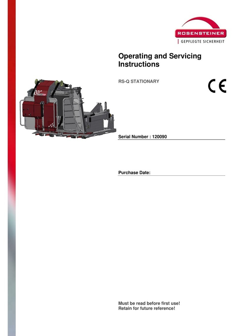
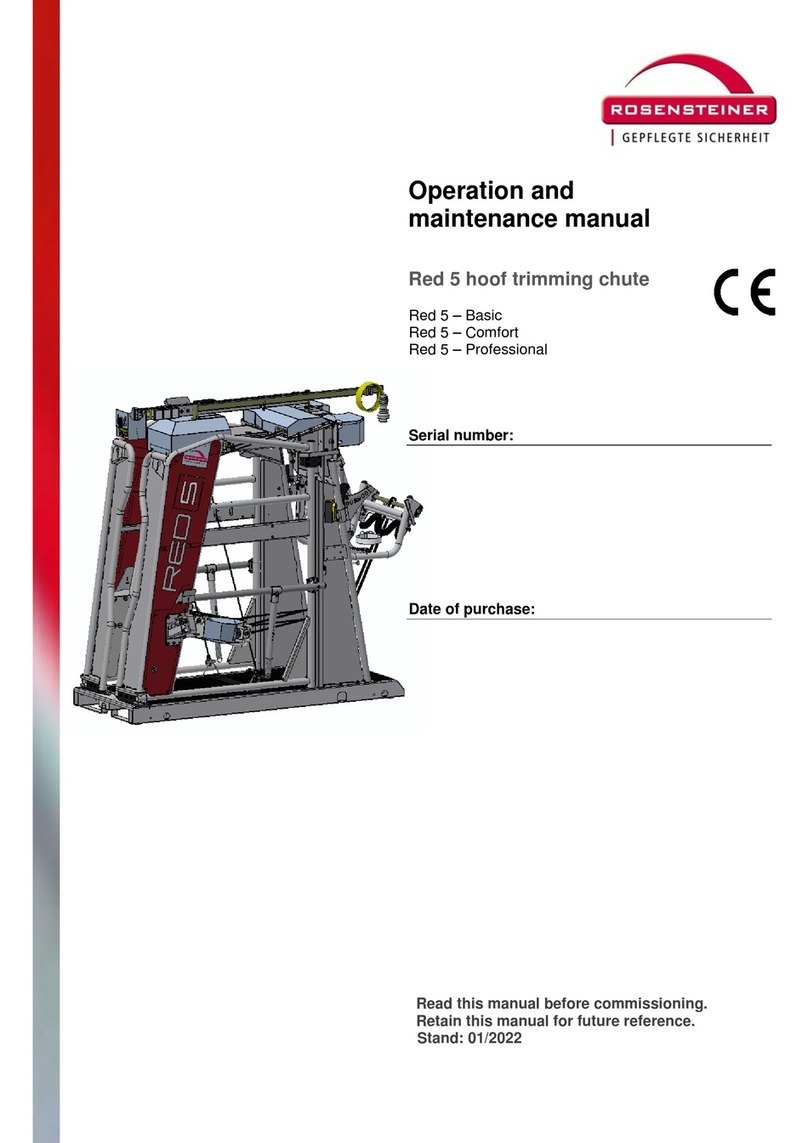
Rosensteiner Kipp Top II Basic User guide

Operating and Servicing
Instructions
Incl. Transfer Documentation
Hoof Trimming Crush Kipp Top
II
Kipp Top II - Basic
Kipp Top II - Comfort
Kipp Top II - Professional
Serial Number:
Purchase Date:
Must be read before first use!
Keep for future reference!
Valid as of: 05/2020

Operating and Servicing Instructions
Page 2of 20
Contents
1INTRODUCTION .................................................................................................................... 2
1.1 About this product ............................................................................................................ 3
1.2 Intended use.....................................................................Fehler! Textmarke nicht definiert.
1.3 Examples of incorrect use.................................................................................................. 4
1.4 EU Declaration of conformity............................................................................................. 5
1.5 Guarantee statement ........................................................Fehler! Textmarke nicht definiert.
1.6 Technical specifications ..................................................................................................... 6
1.7 Data plate.........................................................................Fehler! Textmarke nicht definiert.
1.8 Structure and area of applicability of the operating instructions......................................... 6
1.8.1 Structure.............................................................................Fehler! Textmarke nicht definiert.
1.8.2 Target group.......................................................................Fehler! Textmarke nicht definiert.
1.8.3 Changes to these operating instructions ................................................................................ 7
1.8.4 Safe keeping of the operating instructions ............................................................................. 7
1.8.5 Spatial limits .......................................................................Fehler! Textmarke nicht definiert.
1.8.6 Time limits..........................................................................Fehler! Textmarke nicht definiert.
1.8.7 Operational working space.................................................Fehler! Textmarke nicht definiert.
1.8.8 Explanation of information and hazard notices...................................................................... 7
1.8.9 Pictograms in the operating instructions and on the machine............................................... 8
2TRANSPORT.......................................................................................................................... 9
2.1 Hitching the hoof trimming crush to a tractor..................................................................... 9
2.2 Towing the hoof trimming crush with a tractor .................................................................. 9
2.3 Removal of the hoof trimming crush from the tractor and setting down........................... 10
3STARTING / OPERATION...................................................................................................... 11
3.1 View of appliance / Main operating elements Kipp Top II Comfort.................................... 11
3.2 Safety instructions before starting................................................................................... 12
3.3 Procedure for starting the hoof trimming crush................................................................ 13
4DE-COMMISSIONING / CESSATION OF WORK ...................................................................... 15
5CLEANING.................................................................... FEHLER! TEXTMARKE NICHT DEFINIERT.
6SERVICING / MAINTENANCE / REPAIR ................................................................................. 16
6.1 Safety instructions.............................................................Fehler! Textmarke nicht definiert.
6.2 Electrical hazard.............................................................................................................. 16
6.3 Servicing and care ........................................................................................................... 17
7REPLACEMENT PARTS .................................................. FEHLER! TEXTMARKE NICHT DEFINIERT.
8REGULAR INSPECTION.................................................. FEHLER! TEXTMARKE NICHT DEFINIERT.
9SCOPE OF DELIVERY / ACCESSORIES..................................................................................... 19

Operating and Servicing Instructions
Page 3of 20
1 Introduction
1.1 About this Product
You have purchased equipment with pioneering technology for the care of animal hooves in
the Rosensteiner “Kipp Top II“ hoof trimming crush. The hoof trimming crush is for economic,
periodic and proper care of hooves in a position that is ergonomic, functional and not tiring
for the carer.
The hoof trimming crush is also generally referred to as the equipment in these operating
instructions.
The equipment and its equipment comply with the current applicable state of technology at
the time of introduction to the market. Nonetheless, there remain some hazards. We have
minimised the risk to persons of these hazards as far as possible by design.
This document contains important instructions and provides guidance for safe operation
including all activities necessary for operation like operation, servicing and maintenance.
Following the instructions will help you to avoid hazards and increase the life expectancy of
the equipment. Changes to these instructions by the customer are prohibited.
The documentation from individual sub-contractors and in particular the notices and
instructions specified in them have full validity and must also be adhered to.
The manufacturer accepts no responsibility for any damage arising from non-adherence to
specifications and instructions in the operating instructions or from incorrect use.
The documentation was prepared by us with the greatest care. It is nonetheless possible that
there are minor differences in the content. Please let us know if this is the case.
CAUTION
Modifications by the customer (constructive, functional or procedural) or use of components
and attachments to the equipment nullify the manufacturer’s liability.
WARNING
Intended conversions or changes to the equipment described require a new analysis if
hazards and risk assessment! Original parts and accessories are specially designed for this
equipment. We expressly draw attention to the fact that original parts and accessories not
specified and/or supplied by us have also not been tested and approved by us. Fitting and/or
use of such products could therefore change or adversely affect the constructively specified
properties of your equipment. The manufacturer accepts no liability for damage arising from
the use of non-original parts and accessories.

Operating and Servicing Instructions
Page 4of 20
1.2 Intended Use
The Kipp Top II hoof trimming crush is intended solely for the care of animal hooves.
The hoof trimming crush is suitable for cattle from 300 kg to a maximum of 1000 kg.
Any action other than the “intended use“ constitutes misuse and is thus forbidden. This also
applies to the components of this equipment.
1.3 Examples of Incorrect Use auf
Any use other than, or beyond, the “intended use“.
Operation of the equipment that does not correspond to the requirements of the
safety and hazard aspects or does not comply with the operating instructions. This
also applies to faults arising from inadequate, incorrect or unauthorised work on or
with the equipment.
Any changes, by-passing or de-commissioning of fittings on the equipment which are
there to ensure fault-free function or active and passive safety.
Operation of the equipment in a condition other than technically fault-free.
Non-rectification of faults which adversely affect safety before use of the equipment.
Use of non-authorised auxiliary equipment and tools.
The manufacturer will accept no liability for any damage resulting from misuse.

Operating and Servicing Instructions
Page 5of 20
1.4 EU Declaration of Conformity
Manufacturer and Responsible Body for Documentation:
ROSENSTEINER
Landmaschinenbau GmbH
Zehetner 26a
A-4596 Steinbach / Steyr
Telephone +43(0)7257/7071
Hereby declares that the machine described in these operating instructions:
Type: Kipp Top II Basic
Kipp Top II Comfort
Kipp Top II Professional
Designation: Kipp Top II Hoof Trimming Crush
Manufacturer: Rosensteiner
Complies with the conditions of Guideline 2006/42/EG (for machines).
Steinbach, 01.02.2015
Andreas Rosensteiner, Owner
1.5 Guarantee Statement
Rosensteiner Landmaschinenbau GesmbH provides a guarantee to the purchaser according
to the following conditions:
The guarantee covers the function and quality of the appliance. No guarantee is
offered for signs of wear and tear.
The guarantee period is for one year beginning at the day of delivery to the customer.
All guarantee claims received within the guarantee period by the dealer or in the
factory, Zehetner 26a, A-4596 Steinbach, will be considered.
If faults in the material or manufacture should manifest themselves within the
guarantee period, then guarantee claims should be submitted immediately to the
dealer or the manufacturer.
The faulty appliance or faulty part must be shown to the dealer. Subsequent repair or
replacement may only take place after consultation with. Rosensteiner. No
expenditure will be covered without the express approval of the manufacturer. Faulty
parts must be kept by the dealer or sent to Rosensteiner as agreed: the appliance
must be brought by the customer carriage paid to the dealer.
Guarantee claims cannot be considered if the appliance has been damaged or
destroyed by force majeure. Caution: Guarantee claims also lapse due to incorrect
handling, overloading or service and care work not being carried out!
Guarantee claims will only be considered if the purchase contract, invoice or delivery
note are presented at the same time.
The guarantee offered provides for the repair of the appliance or exchange for a
functioning equivalent.
All further claims, in particular for damage and losses of any kind arising from use of
the appliance are excluded.
If an exchange takes place according to this guarantee initiated by us, guarantee
claims against the dealer as the seller are excluded.

Operating and Servicing Instructions
Page 6of 20
1.6 Technical Specification
Machine type Hoof Trimming Crush Kipp Top II
Dimensions 1960/2130/2060 (L/B/H)
Recommended animal size 300-1000kg
Tare weight 620 - 720 kg
Attachment Three-point attachment Cat II
Cushioning Rubber matting Cow Comfort 30mm
Drive via 220V/1.8kW electro-hydraulic
Upper surface galvanized
Max. Operating pressure 180bar (pre-set)
1.7 Data Plate
The data plate is attached to the top of the operating unit and contains the type designation,
the serial number and the year of construction!
Data Plate Location
1.8 Structure and Area of Applicability of the Operating Instructions
1.8.1 Structure
These operating instructions were written according to the Guideline 2006/42/EG and the
Regulation MSV 2010 implemented from that in Austria. These operating instructions
supports you in becoming familiar with the technical details of the machine, safe and correct
operation and servicing of the machine, and its correct use.
1.8.2 Target Group
The operating instructions are intended for persons tasked with handling the hoof trimming
crush, starting up and operating it and who have the appropriate qualifications for their
activities and functions, i.e. who can evaluate the work and identify possible hazards.
Every person who works with this hoof trimming crush must be familiar with handling the
animals/cattle to be treated.
Every person involved with work on the machine, e.g., operation, maintenance, transport,
must:
Have read and understood these operating instructions before working on the
machine
Follow the instructions and safety advice contained in them.

Operating and Servicing Instructions
Page 7of 20
1.8.3 Changes to these Operating Instructions
These operating instructions illustrate the status of the equipment at the time the operating
instructions were written.
1.8.4 Safe Keeping of these Operating Instructions
These operating instructions must be kept at the place where the equipment is used and
must be accessible to personnel using the equipment! if the operating instructions are lost, a
replacement can be requested from your dealer. If you sell the hoof trimming crush on,
please remember to pass these operating instructions on as well. It is a legal part of your
machine. You can also find the operating instructions on our homepage www.rosensteiner.at
1.8.5 Spatial Limits
The equipment is designed for mobile use at different locations.
1.8.6 Time Limits
Consideration must be given to the lifetime of components used in respect of reliability,
vulnerability to failure and limits of use due to the demands on the equipment.
The following life phases are not considered in these operating instructions:
Manufacture and transport (to the customer / operator)
Maintenance work on the equipment and its components in workshops
Work which requires specialist competence on the part of the person carrying it out,
(welding work, electrical work...)
1.8.7 Operational Working Space
Recommended space requirement for the appliance “Kipp Top II”:
1.8.8 Explanation of the Information and Hazard Notices
Tractor or wall
Drive-out

Operating and Servicing Instructions
Page 8of 20
Useful additional information in free text is labelled with an adjacent info button.
SIGNAL WORD
Type and source of the hazard and the associated risk!
Possible consequences for people, machine parts, tools and workpiece –residual risk!
Actions for avoidance of the risk to life and limb and reduction of the residual risk.
NOTICE
Warns of a possibly hazardous situation which could damage the appliance or an object in its
environment.
CAUTION
Warns of a possibly hazardous situation which could lead to slight bodily injury or material
damage.
WARNING
Warns of a possibly hazardous situation which could lead to serious physical injury or death.
DANGER
Warns of an immediate threat which could lead to severe physical injury or death.
1.8.9 Pictograms in the Operating Instructions and on the Machine
Never step into the hazard zone between the attachment and the machine!
Caution –Crushing hazard!
Read and observe the operating instructions and safety notices before operating!
Switch off motor and remove mains supply before repair, servicing and cleaning work!
Keep sufficient distance away from electrical high voltage supplies!
Use chocks before uncoupling or setting down the machine!
Avoid uneven surfaces and slopes on which the machine could slip, tip or fall!
Take care with escaping high-pressure fluid. Follow instructions in the technical handbook!

Operating and Servicing Instructions
Page 9of 20
Caution -Tipping hazard, secure hoof trimming crush against tipping.
2 Transport
2.1 Hitching the Hoof Trimming Crush to a Tractor
WARNING
To transport the hoof trimming crush by tractor, the balls of the lower link are first connected
to the lower link pin of the Kipp Top II. Then reverse the tractor to the appliance taking care
that no-one is standing in the hazard zone, especially between the tractor and the hoof
trimming crush, lift the lower link until the balls engage with the lower limb. Now just mount
the upper link and secure.
To note when hitching:
Before attaching the hoof trimming crush, ensure that the front of the tractor has
adequate counterweight if necessary.
Never step between the tractor and the hoof trimming crush when hitching, there is a
crushing hazard.
Use suitable bolts with circlips to fit the hoof trimming crush to the upper and lower
links and check for firm seating in the mounting.
When operating the tractor hydraulics, (upper link, lower link) ensure you have a safe
footing with sufficient distance from hazardous movements, never stand on parts of
the tractor auf (lower link…) or the hoof trimming crush
Never step between the hoof trimming crush and the tractor if the tractor is running.
Check transport position.
2.2 Towing the Hoof Trimming Crush with a Tractor
WARNING
Keep sufficient distance from high voltage supply wires during transport.
When transporting the appliance on public roads, observe the traffic regulations of
your country and attach the legally specified lights or warning signs on the appliance.
When driving in the daytime, two warning signs must be attached to the left and the
right of the hoof trimming crush so that the rear lights of the towing vehicle are not
covered. For night driving, a light board with full lighting must be attached to the rear
of the hoof trimming crush muss (lights on the left and the right, like the towing
vehicle).

Operating and Servicing Instructions
Page 10 of 20
Transporting animals with the hoof trimming crush is forbidden without exception!
2.3 Removal of the Hoof Trimming Crush from the Tractor and Setting Down
Proceed as follows to set down the hoof trimming crush:
WARNING
Move to a level set-down location.
Secure the tractor against rolling (handbrake, chocks).
Lower hoof trimming crush. When setting down the hoof trimming crush, ensure that it
is set down so that it cannot tip or slip, especially if it is raised, such as on battens or
pallets etc.
Then release first the upper link then the lower link.

Operating and Servicing Instructions
Page 11 of 20
3 Starting / Operation
3.1 View of the Appliance / Main Operating Elements Kipp Top II Comfort
Item. Designation Item. Designation
01 Locking-catching device 02 Winding rod
03 Drive-in bar 04 Motor switch
05 Lift/lower lever 06 Safety catch
07 Locking lever 08 Foot holder
09 Emergency program cover 10 Plug
11 Catching device 12 Belly strap
13 Head catching device

Operating and Servicing Instructions
Page 12 of 20
3.2 Safety before Starting
NOTICE
When first switching on, you should get the assistance from someone with experience
of the appliance and with hoof care.
Do not carry out hoof care immediately after feeding!
WARNING
These instructions must be carefully read and followed before starting and operating
the equipment.
If the hoof trimming crush is not attached to a suitable towing vehicle, it must be
anchored to the ground!
Adequate ventilation must be ensured when carrying out work.
When working on the hoof trimming crush when it is attached to a tractor, the tractor
must be switched off and secured against re-starting (ignition key removed) and
rolling (handbrake, chocks)
The appliance may only be operated by persons who are familiar with the intended
area of use and handling cattle.
A general visual check of the hoof trimming crush for any changes must be carried
out before use.
Check whether the hoof trimming crush is on a level surface.
Check the hoof trimming crush for loose (especially bolts) or parts hanging down.
Check the hydraulic system for damage, especially the lines and hoses.
Check belt for wear.
Check of the condition of all safety equipment.
Check bolts and tighten if necessary.
The appliance may only be operated with suitable protective measures against too
high contact voltages. RC-switch 30mA trigger current.
Visual check for damage of electrical equipment.
Check whether the electrical inspection is within the annual interval (annual
inspection of the electrical installations by a specialist required)
Check the working area and ensure that no other unauthorised persons are in the
working area –beware of children in particular.
Check the working area and ensure that no other unauthorised persons are in the
working area –beware of children in particular.
Use personal protective equipment.

Operating and Servicing Instructions
Page 13 of 20
3.3 Procedure for starting the Hoof Trimming Crush
See Appliance View(s) for the Numbering in the Following:
1) the hoof trimming rush must be secured against tipping before each start-up!
•Version A: fixing to the ground
to use the hoof trimming crush with a fixed floor mounting, the appliance must be
fixed using four suitable bolts (e.g.: Fischer Anker FBN II 12/20 (12x116) or higher
specification) through the four ground fixing points. The four ground fixing points are
located at the four corners of the sub-frame. The ground must be suitable for fixing
and able to accept an axial loading of at least 20kN per fixing point.
the Kipp Top II is a stationary appliance with appropriate fixing.
•Version B: Attachment to a carrying vehicle
if the hoof trimming crush is used with a carrying vehicle such as a tractor or a loader,
there must be a positive locking non-self-releasing connection to a carrying vehicle.
The carrying vehicle must have a tare weight of at least 2,500kg. a positive-locking
connection would be, for example, fitting with the upper and lower links of the tractor
hydraulics to the three-point connection provided for that or by the locked tool
receptor of a loader.
•Version C: Bespoke Construction
The hoof trimming crush can be secured against tipping using a bespoke expertly
constructed construction. The following conditions must be met:
-Fixing of the bespoke construction to the three-point attachment of the hoof
trimming crush. This is designed for that.
-The construction must be able to receive a force of minimum F3PKT = 20,000N.
See sketch. Appropriate supporting calculations must be made and kept.
-The construction must be made by a specialist operation or by a person with
appropriate skills and knowledge. The materials used, the quality of welded
seams and the fitting material must be suitable for the forces arising.
-The fitting point of the construction on the floor, the wall or other suitable
places must be able to withstand the moment or tensile forces arising.
-Rosensteiner GmbH cannot accept any responsibility for the correct design!
-
2) switch on the unit using the plug (10) (230V, 50Hz) and switch on using the main switch
(4). Beware of escaping high pressure fluid. In the event of injury from hydraulic leaks, seek
immediate medical attention.

Operating and Servicing Instructions
Page 14 of 20
3) lower the table by pulling the lever (5). (ensure that the appliance is sufficiently secured
against tipping)
4) Open the catching device (6) by pulling the locking lever (7) and fold the head bar (13) out
into the working position and lock it using the spring lock.
5) Open the drive-in gate (11) using the unlocking lever(1).
6) close the catching device at a suitable position for catching and ensure that the soring bolt
is engaged, and the catching device can no longer move up.
7) Lay the belly strap flat on the floor so that the animal steps over it and hang it in the holder
on the front of the operating unit.
8) Push the animal from the rear into the appliance and close the drive-in gate (11) behind
the animal by simply pushing shut. Then close the catching device (6) tighter so that the
head is fixed. How far the closing device closes can be set by adjusting the stop point of the
closing device simply with the clip pin. This stop point is located at the end of the spar tube.
9) Lay the belly strap (12) by hand on the animal from the rear (behind the hip bone) until the
strap is loosely on the body of the animal. Now tighten it by half a turn. Tighten the belly strap
at the front by hand until the strap is loosely on the body.
10) tighten the belt hydraulically until the stop limit
11) Tip the table by 45°. Do this by moving the lever (5) upwards.
12) Lay the feet on the foot-holder shaped rubber part, lay the strap over them and then lay
the chain in the chain sprocket. Then pull the chain from behind over to the front and tighten
it. The foot is now fixed.
13) The foot holder can simply be pulled out to adjust the height; the fixing flap must be lifted
to push it in.
14) Tip the table until it is completely flat against the limit stop.
15)Carry out hoof care. When using rotating tools, wear safety glasses and safety gloves.
16)Only angle grinders with a guard may be used
17)Angle grinders may only be placed in holders after the disc has come to a complete stop.
18)Push release flaps completely upwards until they engage for all 4 foot-holders.
19) Move the table back to a 45°position, turn the chain sprocket again by pulling the release
lever, and release the feet. Push the foot holder completely back ensuring that the flaps are
moved back to the locking position.
20)Lower the table to the limit stop, release the strap and place it in the original position,
open the catching device (6) with the lever (4) and drive the animal out.
Version B: Securing Manually Led Animals with Halter
1) Set the catching bar at the centre position
2) Walk in front of the animal through the drive-in bar so that the animal’s head is level with
the head frame.
3) Secure the halter on the bottom of the head frame to the rope holder.
4) Then also close the catching device to avoid head movement by the animal
5) Attach strap and carry out the work as previously described.

Operating and Servicing Instructions
Page 15 of 20
Catching Device Position for Driving
in with a Halter
4 Decommissioning / Cessation of Work
See appliance view(s) for numbering in the following.
If there are interruptions to work, or at the end of work, the ignition key of the tractor
must be removed.
CAUTION
The following procedure must be followed where there are interruptions to work or work
ceases:
1) Before the table is tipped to the horizontal, the catching device should be turned
towards the rubber mat. If other operating elements need to be moved out of the work
position, this must be done before tipping.
2) The table must be brought to the horizontal until it is lying on the rubber limit stop
before switching off. This prevents any further movement of the table or tipping of the
appliance.
3) Switch off motor (04) and unplug appliance.
Switching on:
1) Tip the table to the vertical and open catching device.
2) If other actions have been undertaken, move these to the work position as well (drive-
in gate, head frame…)
NOTE
Check transport settings (for transport, the drive-in gate is completely closed until the last
catch of the lock is engaged. The head frame is rotated inwards until it is on the rubber mat,
then the catching device is closed).

Operating and Servicing Instructions
Page 16 of 20
5 Cleaning
NOTICE
If cleaning agents are used, follow the safety instructions in the accompanying safety
data sheet.
Dispose of cleaning water according to the national regulations.
When cleaning with high pressure cleaners, wear safety glasses.
Do not clean electrical components (switched, plugs etc.) directly with high pressure
jets.
6 Servicing / Maintenance / Repair
6.1 Safety Notices
CAUTION
Maintenance work may only be carried out by trained and qualified personnel or by
the manufacturer.
Servicing and maintenance work may only be completed if there is suitable lighting
present for the work to be carried out.
Servicing work may only be carried out if the machine is switched off.
6.2 Electrical Hazard
DANGER
Contact with Live Components.
Effects of electrical current on humans.
Compliance with legal regulations for installation, operation, maintenance and
inspection of electrical equipment.
Only allow electrical work to be carried out by electrical specialists.
Have damaged installations repaired immediately by specialist personnel.
Use of suitable plugs and connections.
Recurrent inspections.
Always switch off and protect against re-starting before opening electrical appliance
covers.
Maintenance personnel must be familiar with all technical standards and regulations.
Unexpected changes to operating conditions can lead to injury.
Check that any released bolt connections are re-tightened before starting.

Operating and Servicing Instructions
Page 17 of 20
Loosening bolt connections: when opening bolted connections, open them slowly to
release pressure in the lines.
Opening of outlet points with bolt connections: do not remove bolt connections of
outlet points until the system is de-pressurised.
The pressure must be completely released before opening pipe connections and
pressurised systems
6.3 Servicing and Care
The following actions will increase operational safety and extend the life of your
appliance:
All joints must be lubricated regularly and after any cleaning with a high-pressure
cleaner.
(table swivel, winding stroke-cylinder and catching device)
Check hydraulic oil level periodically and top up if necessary. Oil change one year
after first commissioning. Subsequent oil changes every two years. Original filling:
Hydraulic oil HLP46, Quantity: Basic, Comfort 6l
Professional 6.5l
NOTICE
Check bolts (especially on the hydraulic system) after every 5 starts and tighten if
required.
Repair or change damaged parts immediately. Working with damaged parts can be a
hazard to you and to the animal.
Hoses and hose connections are subject to natural ageing even with correct storage
and approved load. This means they have a defined lifetime. The lifetime of a hose
connection including any storage time of the hose should not exceed six years.
Storage time should not exceed two years in accordance with DIN 20 066.
7 Replacement Parts
HINWEIS
If a component of the machine needs to be replaced, original parts must be used.
Replacement and consumable parts for original components and accessories not
supplied by the manufacturer of the machine are not tested and approved by the
manufacturer.
Installation and/or use of such products could alter the constructively specified
properties of the machine and endanger safety.
The manufacturer will accept no responsibility of any kind for damage or subsequent
losses arising from the use of non-original replacement parts and accessories, or
incorrect fitting or exchange of original parts and accessories and the guarantee will
no longer be valid.

Operating and Servicing Instructions
Page 18 of 20
After expiry of the guarantee period, we recommend the use of original parts to
ensure constant efficiency of the machine. In the event of guarantee claims, please
contact your local sales and service partner.
8 Regular Inspection
NOTICE
The electrical installation of the machine must be subjected to an annual inspection by a
qualified person.

Operating and Servicing Instructions
Page 19 of 20
9 Scope of Delivery / Accessories
Series equipment:
Head frame (mechanical sliding door open at the bottom–considers every head
position for easy drive-in)
Hydraulic belly-strap tensioning
Central operation from the workplace
Close drive-in bar for faster drive-in
Three-point Cat II, 4-sided fork-lift truck lift point, 2-sided lift truck lift point
High quality Bosch Rexroth hydraulic unit with a 1.8kW electric motor
Rubber mat Cow Comfort 30mm
4 foot-holders d. 40mm with chain lock, re-tensionable, self-locking height
adjustment, extremely fast
Complete strap system (belly strap, foot strap)
Toolbox with 3 sockets
Bolt points for floor-fixing
Easily accessible service openings
Complete base frame galvanised
Art. No. Type Description
14 000B Kipp Top II Basic according to series equipment
14 000C Kipp Top II Comfort
omech. Drive-in gate
oEquipment box for tools
(2x flex, 2x knife-holder)
14 000P Kipp Top II Professionell
oHydraulic drive-in gate
oEquipment box for tools
(2x flex, 2x knife-holders)
oEmergency program connector to tractor for external
hydraulics
(in case of power failure)
Art. Nr. Accessories
16400 Drive grate set „Klauenpflege Comfort“
16401 Attachment for drive grate set
14610 Mechanical drive-in gate for simple drive-in/out, gate is closed
manually also serves as table extension,
14620 Hydraulic drive-in gate for simple drive-in/out, operation is via
central operating unit, also serves as table extension
14630 Equipment box for tools (2x flex, 2x knife holder)
14670 Emergency program connection for external hydraulics (from
the tractor in the event of a power failure or for working in the
field or meadow)
16410 Fischer anchor (12x116) for fixing to the ground, set of 4.

HANDOVER DECLARATION
APPLIANCE DATA
Appliance / Type:*
Serial number:*
Delivery note no.:
Additional equipment:
CUSTOMER INFORMATION
Name:*
Street:
Post code / City:*
Telephone:*
E-mail:
OPERATION DATA
Farmer
10-25 cattle
26-60 cattle
61-200 cattle
201-900 cattle
>900 cattle
Professional hoof
trimmer
up to 5000 animals/year
over 5000 animals/year
Community
Pasture
Arable
Fruit growing
Forestry
Side-line activity
Commune
Contractor
Business
Yes, I would like to receive the free Rosensteiner newsletter (e-mail address required)
I agree to being named as a reference customer.
I confirm that the operating instructions were handed to me with the appliance, and that the operating, safety and
servicing regulations were also explained to me.
Date:
Customer/recipient signature:
DEALER INFORMATION
Company:*
Salesperson:
Postcode/city:*
Recommendation for press release
Handover photos taken
I confirm that I have correctly handed over the appliance to the customer.
Date:
Dealer/transferrer signature:
PLEAS FAX FULLY COMPLETED FORM TO +43(0)7257/7071 4
Field marked * are mandatory!
This manual suits for next models
2
Table of contents
Other Rosensteiner Farm Equipment manuals

Rosensteiner
Rosensteiner 901557 User manual

Rosensteiner
Rosensteiner Red 5 User manual

Rosensteiner
Rosensteiner VET PRO STATIONARY User guide

Rosensteiner
Rosensteiner Red 5 User manual

Rosensteiner
Rosensteiner RS-Q STATIONARY User guide

Rosensteiner
Rosensteiner BULL TOP S User manual

Rosensteiner
Rosensteiner RED Q Guide