Soilmoisture Equipment 2900F1 User manual

SOILMOISTURE EQUIPMENT CORP.
P.O. Box 30025, Santa Barbara, CA 93105 U.S.A.
Telephone 805-964-3525 - Fax No. 805-683-2189
SOILMOISTURE
INSTRUCTIONS
OPERATING
Model 2900F1 “QUICK DRAW” SOILMOISTURE PROBE May 2012
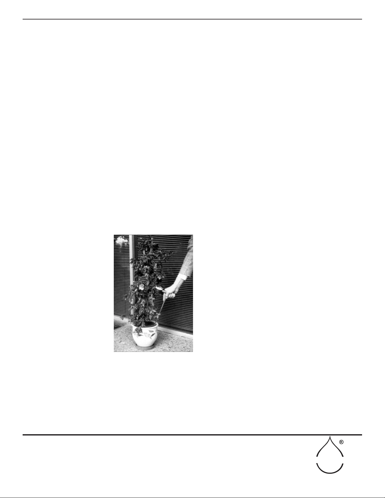
The 2900F1 QuickDraw Soilmoisture Probe is the most effective portable moisture measuring instrument
available. Designed for rugged eld use, the thermos construction utilizing capillary tube connections and super
porous ceramic tip assures fast response and accurate readings, independent of temperature differences. The self-
servicing feature, unique in tensiometer construction, eliminates the need for accessory service kits, and assures fast
response times after years of use.
The Probe is shipped in a dry condition for greater convenience in handling and storage over a period of time. Fol-
low the simple instructions to water ll your unit in preparation for use.
Figure 1 - 2900F1 Soilmoisture "Quick Draw" Probe

SOILMOISTURE EQUIPMENT CORP.
P.O. Box 30025, Santa Barbara, CA 93105 U.S.A.
Telephone 805-964-3525 - Fax No. 805-683-2189
SOILMOISTURE
2
TABLE OF CONTENTS
Table of Contents.................................................................................................................................................... Page 2
Unpacking ...................................................................................................................................................... Page 3
Cautions & Warnings.............................................................................................................................................. Page 3
Warranty & Liability............................................................................................................................................... Page 3
Aquaint Yourself With The Parts ........................................................................................................................... Page 4
Theory of Operation................................................................................................................................................ Page 5
Requirements Prior to Use/Initial Filling................................................................................................................ Page 5
IMPORTANT NOTE ................................................................................................................... Page 5
Venting and Adjusting Dial Gauge............................................................................................... Page 6
Effects of Altitude on Operation of the Probe .............................................................................. Page 6
Initial Filling ................................................................................................................................. Page 7
Response Time too long .............................................................................................................. Page 10
About the Dial Gauge and Carrying Case ................................................................................... Page 10
Making a Soil Moisture Measurement................................................................................................................... Page 11
Coring a hole................................................................................................................................ Page 11
Inserting the Probe....................................................................................................................... Page 12
Making a Reading.................................................................................................................................................. Page 13
Dial Gauge Pressure Build-up ..................................................................................................... Page 14
Irrigation Scheduling ................................................................................................................... Page 15
Routine Measurements........................................................................................................................................... Page 16
Potted Plants ................................................................................................................................ Page 16
Using a number of probes at the same time................................................................................. Page 16
Troubleshooting......................................................................................................................................................Page16
Substantial change in the Vacuum Level..................................................................................... Page 16
Lack of response from Gauge...................................................................................................... Page 17
50 centibars cannot be reached.................................................................................................... Page 17
Replacing the Ceramic Tip .................................................................................................................................... Page 18
Replacing the Dial Gauge...................................................................................................................................... Page 20
Time Required to make a Reading......................................................................................................................... Page 22
Care and Maintenance............................................................................................................................................ Page 23
Tips for Scheduling Irrigations .............................................................................................................................. Page 24
Parts List ..................................................................................................................................................... Page 26

3
SOILMOISTURE EQUIPMENT CORP.
P.O. Box 30025, Santa Barbara, CA 93105 U.S.A.
Telephone 805-964-3525 - Fax No. 805-683-2189
SOILMOISTURE
Soilmoisture Equipment Corp. (SEC) warrants all products manufactured by SEC to be free
from defects in materials and workmanship under normal use and service for twelve (12) months
from the date of invoice provided the section below has been met.
Soilmoisture Equipment Corp. (SEC) is not liable for any damages, actual or inferred, caused
by misuse or improper handling of its products. SEC products are designed to be used solely as
described in these product operating instructions by a prudent individual under normal operating
conditions in applications intended for use by this product.
WARRANTY & LIABILITY
UNPACKING
CAUTIONS & WARNINGS
The Soilmoisture "Quick Draw" Probe should be removed from the eld prior to the onset of
freezing conditions. Since the Probe is a water-lled system, it is essential that the unit be stored
and used at temperatures above freezing. Freezing temperatures, of course, will cause the water
within the unit to freeze and expand as ice is formed. This can cause breakage of the ceramic
tip and distort or rupture the thin-walled Bourdon tube within the dial gauge.
If the Bourdon tube is ruptured, the dial gauge cannot be repaired and will have to be replaced.
If the Bourdon tube is distorted but not ruptured, it may be possible to reset the pointer on the
gauge to correct the change in calibration caused by freezing.
Intense heat can cause the plastic Carrying Case to distort and can result in the evaporation of
all water from the sponge within the Carrying Case. This will be detrimental to the operation
of the Soilmoisture Probe. It will also result in frequent servicing for removal of air. Do not
subject the Soilmoisture Probe to intense heat while storing or transporting it. Very high tem-
peratures can develop within a closed cab of a truck or the trunk of a car.
Not Liable for improper use. Remove all packing materials and check the 2900F1 Soilmois-
ture "Quick Draw" Probe for any damage that may have occurred during shipment. If the
Sampler is damaged, call the carrier immediately to report it. Keep the shipping container and
all evidence to support your claim.
Do not bump or drop the dial gauge or ceramic sensing tip or they could break and will need to
be replaced. Take care not to let the sensing tip come in contact with grease or any other similar
material that could clog the pores of the ceramic.
Please verify that your shipment is complete.

4
SOILMOISTURE EQUIPMENT CORP.
P.O. Box 30025, Santa Barbara, CA 93105 U.S.A.
Telephone 805-964-3525 - Fax No. 805-683-2189
www.soilmoisture.com - sales@soilmoisture.com
SOILMOISTURE
Figure 2 - 2900K1 Parts
AQUAINT YOURSELF WITH THE PARTS
The Probe, Coring Tool, and Cleaning Rod are held in place by the molded plastic
retainers at the top of the Carrying Case.
NOTE: The Probe ts into the side of the Carrying Case marked “PROBE”, and
the Coring Tool ts into the side marked “CORING TOOL” (Fig. 3).
It is very important to keep the Probe in the side of the Carrying Case marked
“PROBE” when it is not actually being inserted in the soil, because this side of the
Carrying Case has a water storage reservoir, or sponge cartridge, at the bottom.
During the “Initial Filling” operation, pictured and described on pages 7 through
10, you will ll the water storage reservoir. Thereafter, the sensing tip of the Probe
will be kept moist.
An Accessory Kit (2900FK1) is provided with each Probe. It consists of a small
screwdriver, a 3/32” Allen Wrench, Replacement Ceramic Sensing Tips, O-Rings
and ¼ Oz. Silicone Grease Kit. The screwdriver is used to vent and adjust the dial
gauge and to replace the Sensing Tip. The Allen Wrench is used in the event the
Vacuum Dial Gauge needs replacement.
PROBE CORING
TOOL
CLEANING
ROD
PROBE
CASE
Figure 3 - Probe Case Tool Placement
DIAL GAUGE
NULL KNOB
POROUS CERAMIC
SENSING TIP
CLEANING RODCARRYING CASE PROBE CORING TOOL
WATER STORAGE
RESERVOIR
(SPONGE CARTRIDGE)
ACCESSORY
KIT
TOP
TOP
GREASE
SILICONE
MFJ012PK

SOILMOISTURE EQUIPMENT CORP.
P.O. Box 30025, Santa Barbara, CA 93105 U.S.A.
Telephone 805-964-3525 - Fax No. 805-683-2189
www.soilmoisture.com - sales@soilmoisture.com
SOILMOISTURE
55
THEORY OF OPERATION
The Model 2900F Soilmoisture Probe is a tensiometer-type instrument that reads soil
suction directly. The “soil suction” reading is a direct measure of the availability of
moisture for plant growth, and the standard unit of measurement is the “bar”. The bar*
is a unit of pressure in the metric system and is used to dene positive pressure (above
atmospheric pressure), or negative pressure or vacuum (below atmospheric pressure).
The gauge on the Probe is calibrated in hundredths of a bar (or centibars) of vacuum,
and is graduated from zero to 100.
In scientic work, it is becoming customary to express pressures and vacuums in a
unit of measure called a “Pascal”, and a “Kilopascal” which is 1000 times as large as
a Pascal. A “centibar”, as used above, is exactly equal to a Kilopascal. Therefore, the
dial gauge on the Probe also reads in Kilopascals and is graduated from zero to 100
Kilopascals (KPa).
Soil suction is actually created by the attraction that each soil particle has for the water
in the soil. Because of this attraction, water forms a lm around each particle of soil
and collects in the capillary spaces between the soil particles. As the soil becomes
drier, these lms become thinner and the attraction or soil suction increases. The plant
root has to over-come this soil suction, or attraction force, in order to withdraw mois-
ture from the soil. The measurement of soil suction then gives a direct indication of the
amount of work the plant root must do to get water from the soil. The only moisture
measuring instruments that accurately measure soil suction are those using the ten-
siometer principle. These instruments read centibars of soil suction directly without
calibration for soil type, salinity, or temperature.
When the Probe is inserted into the cored hole, there are various effects associated with
the movement of the porous ceramic sensing tip through the soil. The soil surrounding
the tip is slightly compacted and the wiping action of the porous ceramic through the
soil causes small thermal effects. It takes a few moments for these disturbances to dis-
perse, and this is the reason that it is not desirable to move the Null Knob for the rst
minute after insertion of the Probe.
In order to obtain a soil suction reading, it is necessary for a small amount of water
to transfer between the sensing tip of the Probe and the soil. When the Null Knob is
turned clockwise, water is forced out of the Probe sensing tip and into the surrounding
soil. When the Null Knob is turned counterclockwise, a vacuum is created within the
Probe, which causes moisture to move from the soil through the ceramic sensing tip
and into the Probe. In order to obtain an accurate reading within the minimum amount
of time, one must be careful not to disturb the moisture conditions surrounding the
Sensing Tip.
IMPORTANT NOTE: When examining the Probe, DO NOT leave the porous
ceramic sensing tip exposed to the air for prolonged periods.
When the Probe is removed from the Carrying Case and the Sensing Tip is not kept
moist, evaporation of moisture from the Tip will pull the dial gauge up to a very high
centibar reading. Under these conditions, air can diffuse through the water in the pores
of the Sensing Tip and enter the Probe, which can result in a decrease in sensitivity and
require a relling cycle.
REQUIREMENTS PRIOR TO USE
6
SOILMOISTURE EQUIPMENT CORP.
P.O. Box 30025, Santa Barbara, CA 93105 U.S.A.
Telephone 805-964-3525 - Fax No. 805-683-2189
www.soilmoisture.com - sales@soilmoisture.com
SOILMOISTURE
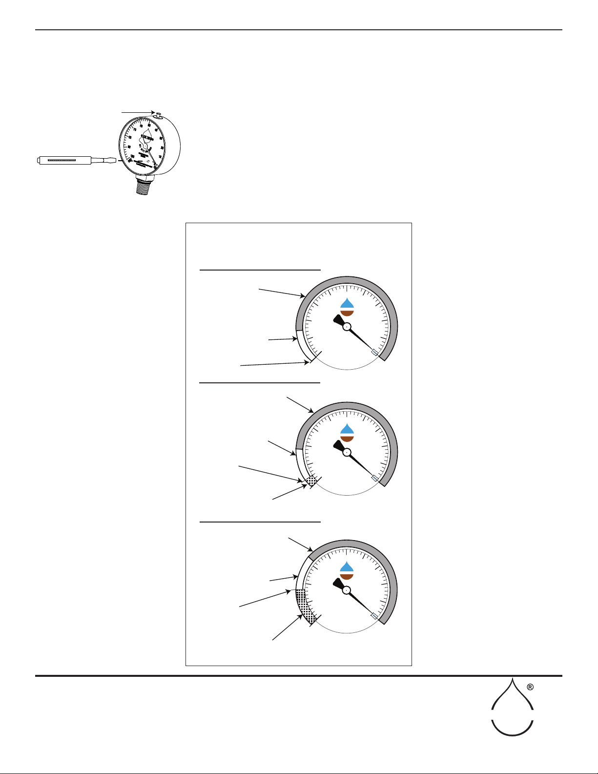
Venting and Adjusting
the Dial Gauge
The 2060FG dial gauge is hermetically sealed, therefore, the vent pin must be
pressed prior to use. Temperature or altitude changes could create internal pressure
which could give a less accurate reading.
First, simply press the vent pin located, at the top of the gauge, to release any col-
lected air. Located on the face of the gauge is an insertion point for a small at-
head screwdriver. If the gauge is reading high, turn the screwdriver clockwise an
estimated amount to correct the error. If the gauge reads low, turn the screwdriver
counterclockwise an estimated amount to correct the error. Repeat the process if
necessary until the pointer is on zero.
VENT PIN
EFFECTS OF ALTITUDE ON OPERATION OF THE PROBE
PRACTICAL READING RANGE
0 TO 85 CENTIBARS
IN THIS RANGE AIR COMING
OUT OF SOLUTION MAKES
READING INACCURATE
THEORETICAL LIMIT
OF READING
AT SEA LEVEL
PRACTICAL READING RANGE
0 TO 81 CENTIBARS
IN THIS RANGE AIR COMING
OUT OF SOLUTION MAKES
READING INACCURATE
THEORETICAL LIMIT
OF READING
IN THIS RANGE WATER
BREAKS INTO A VAPOR
CAUSING UNIT TO LOSE
ALL OF ITS WATER
AT 1000 FT.
ABOVE SEA LEVEL
CENTIBARS OF SOIL
SUCTION
SOILMOISTURE EQUIPMENT CORP
Santa Barbara, CA USA
90
80
70 60 50 40
30
20
10
0
DRY
WET
100
D
O
N
O
T
F
R
E
E
Z
E
SOILMOISTURE
CENTIBARS OF SOIL
SUCTION
SOILMOISTURE EQUIPMENT CORP
Santa Barbara, CA USA
90
80
70 60 50 40
30
20
10
0
DRY
WET
100
D
O
N
O
T
F
R
E
E
Z
E
SOILMOISTURE
AT 5000 FT.
ABOVE SEA LEVEL
CENTIBARS OF SOIL
SUCTION
SOILMOISTURE EQUIPMENT CORP
Santa Barbara, CA USA
90
80
70 60 50 40
30
20
10
0
DRY
WET
100
D
O
N
O
T
F
R
E
E
Z
E
SOILMOISTURE
PRACTICAL READING RANGE
0 TO 68 CENTIBARS
IN THIS RANGE AIR COMING
OUT OF SOLUTION MAKES
READING INAACURATE
THEORETICAL LIMIT
OF READING
IN THIS RANGE WATER
BREAKS INTO A VAPOR
CAUSING UNIT TO LOSE
ALL OF ITS WATER
The Reading Range is Reduced Approximately 3.5 Centibars
for Each 1000 Ft. Increase in Elevation
Figure 4 - Venting and adjusting the gauge
Figure 5 - Effects of Altitude
REQUIREMENTS PRIOR TO USE (CONT.)

7
SOILMOISTURE EQUIPMENT CORP.
P.O. Box 30025, Santa Barbara, CA 93105 U.S.A.
Telephone 805-964-3525 - Fax No. 805-683-2189
www.soilmoisture.com - sales@soilmoisture.com
SOILMOISTURE
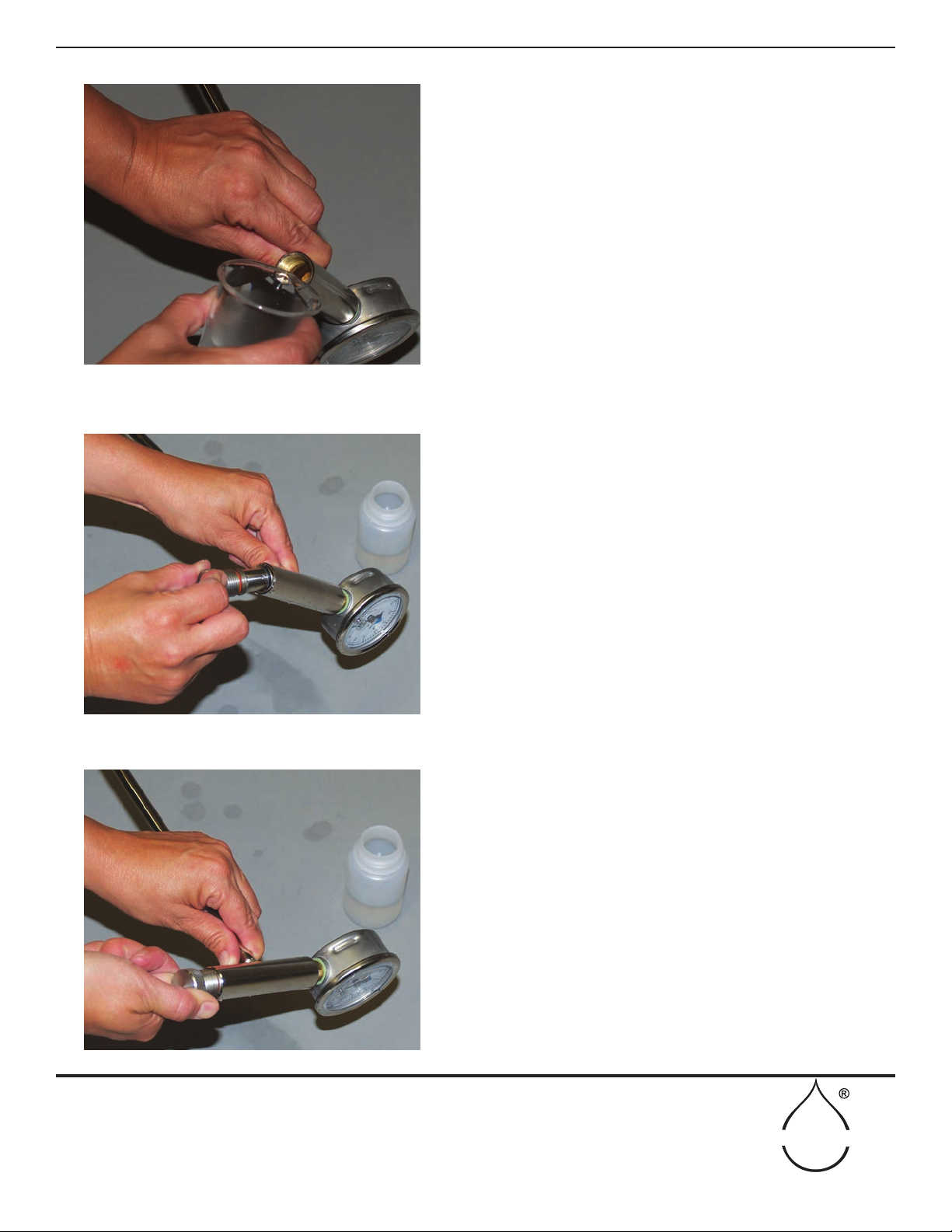
STEP 1
Turn Null Knob clockwise as far as it will go and then
insert the porous ceramic sensing tip in water.
STEP 2
Keep the sensing tip in water. Turn the Null Knob coun-
terclockwise until you just see the red ring.
On initial lling, the pointer will normally rise to a reading
of 40 to 50. Let the pointer drop to zero.
STEP 3
Keep the sensing tip in water. Continue to turn the Null
Knob slowly counterclockwise until it is loose and can be
removed.
REQUIREMENTS PRIOR TO USE / INITIAL FILLING
RED RING
Figure 8
Figure 7
Figure 6
8
SOILMOISTURE EQUIPMENT CORP.
P.O. Box 30025, Santa Barbara, CA 93105 U.S.A.
Telephone 805-964-3525 - Fax No. 805-683-2189
www.soilmoisture.com - sales@soilmoisture.com
SOILMOISTURE
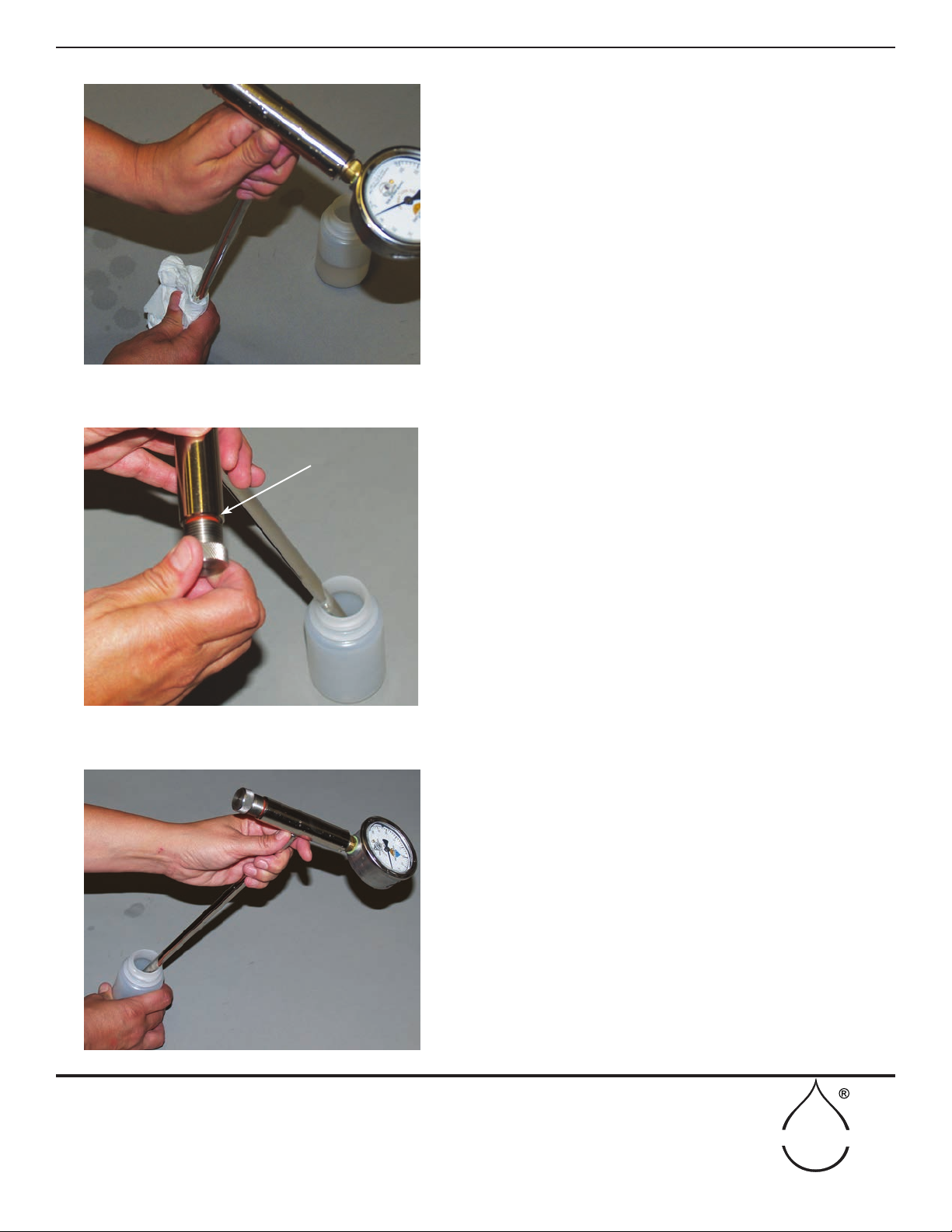
STEP 4
Fill the handle with water. A teaspoon works well for this
operation. Water should be poured into the handle slowly
and carefully so that air bubbles are not trapped. If you see a
bubble clinging to the smooth wall or bottom of the handle
cavity, nudge it free with the sharp end of a pencil.
STEP 5
Screw the Null Knob completely back in the Handle, which
will push out excess water.
While you are doing this, water will ooze out through the
porous ceramic tip and drip off the end.
STEP 6
Turn the Null Knob clockwise as far as it will go.
REQUIREMENTS PRIOR TO USE / INITIAL FILLING (cont.)
Figure 10
Figure 11
Figure 9
9
SOILMOISTURE EQUIPMENT CORP.
P.O. Box 30025, Santa Barbara, CA 93105 U.S.A.
Telephone 805-964-3525 - Fax No. 805-683-2189
www.soilmoisture.com - sales@soilmoisture.com
SOILMOISTURE
STEP 7
Remove the tip from the water and dry it with an absorbent
tissue. The dial pointer will rise to a reading of 20 or 30 as
moisture is pulled into the dry tissue.
STEP 8
Turn the Null Knob counterclockwise until you just see the
red ring. The pointer will normally rise to a reading of 80
or 90 centibars if you live at an elevation between sea level
and about 2000 ft. If you live at higher elevations, the maxi-
mum reading will be somewhat lower. See page 14, which
describes the effect of altitude on the operation of the Probe.
If the pointer does not rise it can mean that rough handling
has cracked the porous ceramic sensing tip. See section on
“Care and Maintenance” for corrective action.
STEP 9
Immerse the porous sensing tip again in water and wait until
the pointer drops to zero.
REQUIREMENTS PRIOR TO USE / INITIAL FILLING (cont.)
RED RING
Figure 13
Figure 12
Figure 14

10
SOILMOISTURE EQUIPMENT CORP.
P.O. Box 30025, Santa Barbara, CA 93105 U.S.A.
Telephone 805-964-3525 - Fax No. 805-683-2189
www.soilmoisture.com - sales@soilmoisture.com
SOILMOISTURE
STEP 10
Repeat Step 3, removing the Null Knob again while the sensing tip is in the
water. Repeat Steps 4, 5, and 6, again relling the handle with water. Insert
the Null Knob and turn it clockwise as far as it will go.
STEP 11
Check Response Time. To do this, wipe the Probe and porous ceramic tip
with absorbent tissue to remove all excess water. Turn the Null Knob until
the pointer reaches a reading of 50 on the dial. Now when you dip the sensing
tip in the water, the pointer will normally drop from a reading of 50 to 10 in
approximately one second - the time that it takes to say “one, one thousand”.
The Probe is ready for use if the response time is approximately one second.
STEP 12
Fill the Carrying Case tube, which is labeled “PROBE” with water and allow
it to stand for a minute or two (Fig.15). This will ll the sponge cartridge with
water. Empty out excess water and insert the Probe. The sponge cartridge in
the Carrying Case will now keep the porous ceramic sensing tip wet so it is
ready to use at any time in the eld. In the future, always keep the Probe in
the Carrying Case when not in use.
REQUIREMENTS PRIOR TO USE / INITIAL FILLING (cont.)
After initial lling, if the response time is considerably more than one second, it usu-
ally indicates that an air bubble has been trapped in the handle. To correct this, simply
repeat Steps 8 and 9, then Steps 3, 4, 5, and 6. Again look into the handle cavity after
lling to see if there are any bubbles clinging to the internal wall. In the event there
are bubbles, simply nudge them loose with the sharp end of a pencil. Fill the cavity in
the handle to the top, replace the Null Knob, wipe it dry, and again check the response
time.
NOTE: The pointer may have to be adjusted after the lling operation.
When the Probe is in the Carrying Case and is held vertically, the pointer on the dial
gauge should read zero. You will note, however, that if the Carrying Case is tipped
horizontally, the pointer on the dial gauge will read below zero. This is caused by the
shift in weight of the water column within the Probe. For normal use, the dial pointer
is set at zero when the Probe is held vertically and only when the ceramic sensing tip
is immersed in water. For pointer setting instructions, refer to page 6, "Venting and
Adjusting the Dial Gauge".
Response time is too
long
About the Dial Gauge
and Carrying Case
Figure 15 - Filling the probe with water
11
SOILMOISTURE EQUIPMENT CORP.
P.O. Box 30025, Santa Barbara, CA 93105 U.S.A.
Telephone 805-964-3525 - Fax No. 805-683-2189
www.soilmoisture.com - sales@soilmoisture.com
SOILMOISTURE
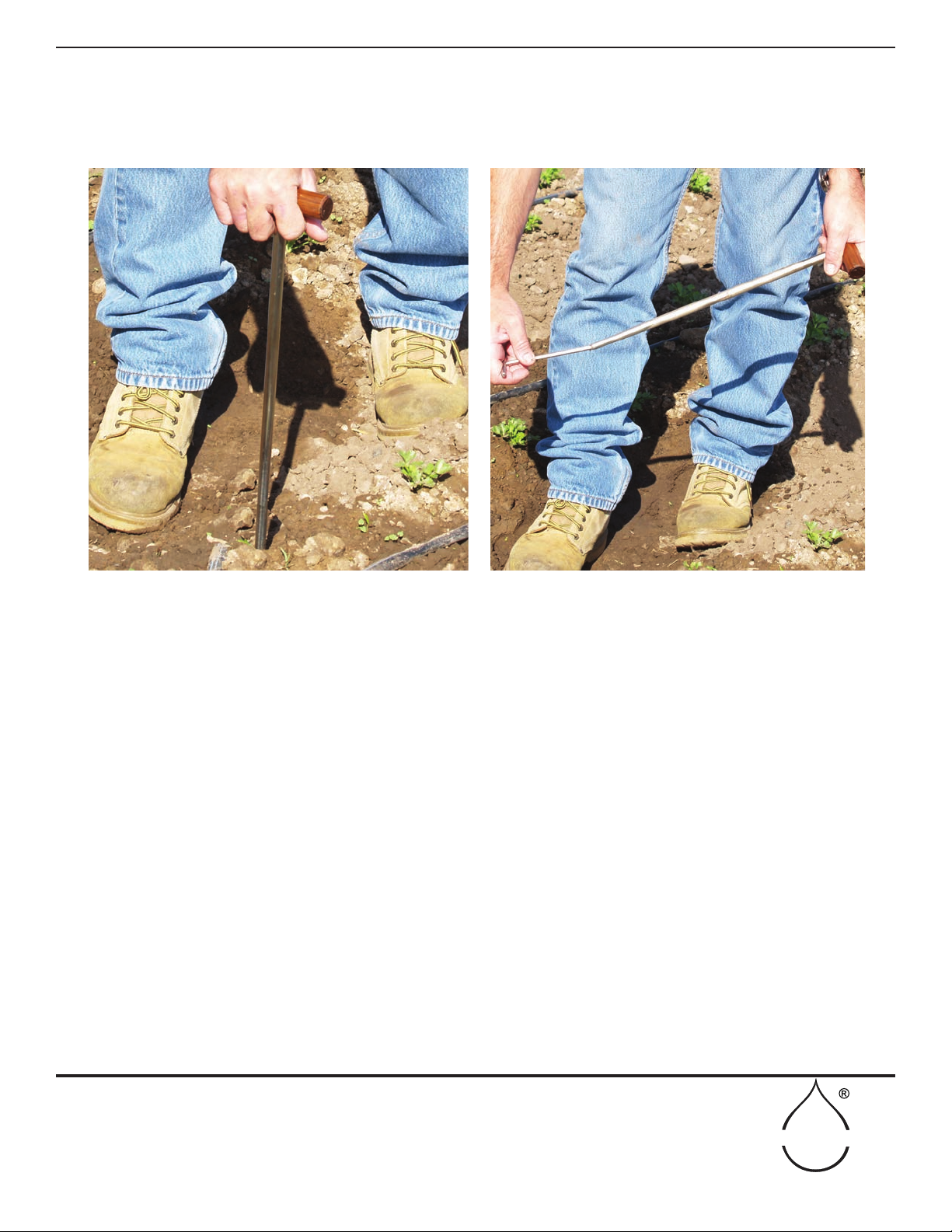
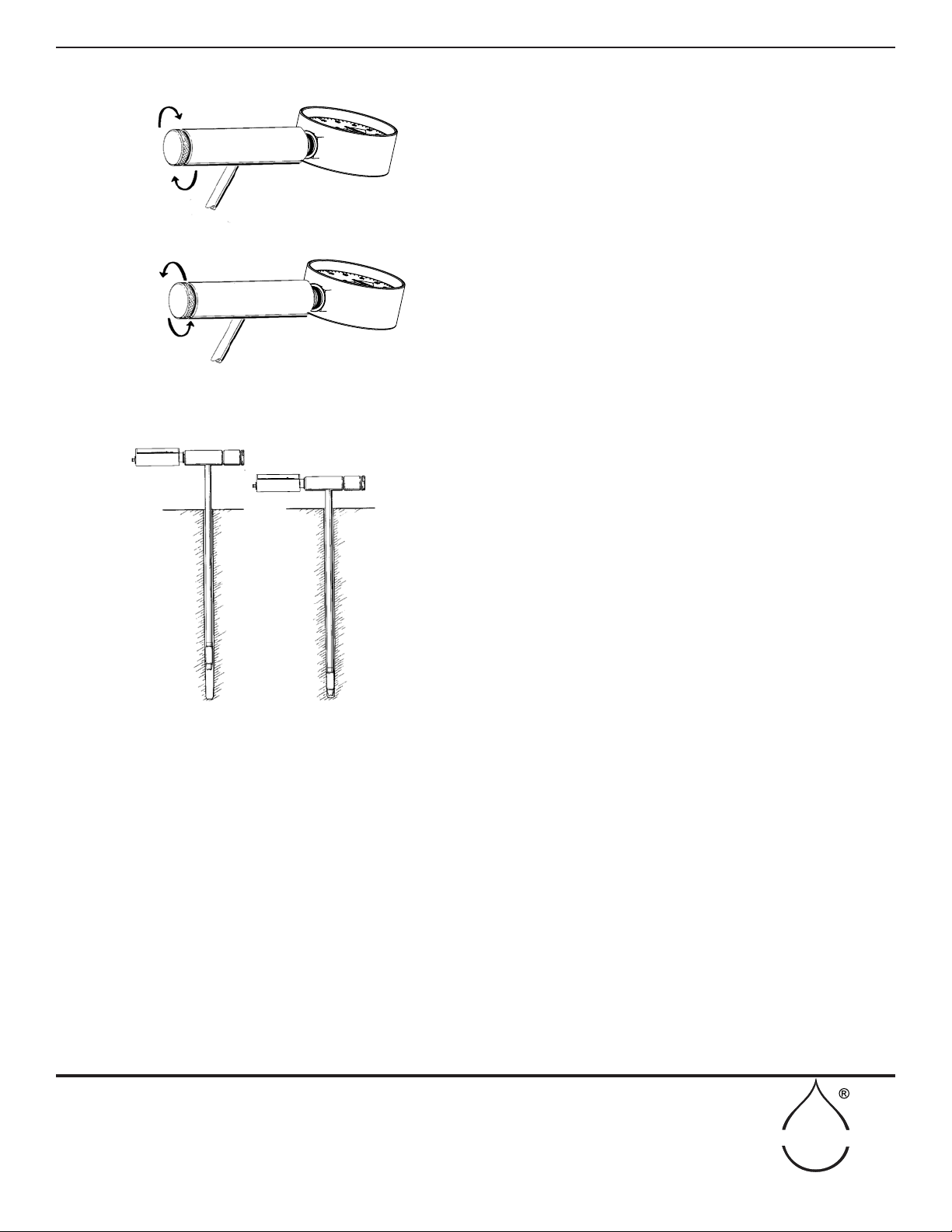
CORING A HOLE
The rst operation in taking a reading is to core a hole to accept the Probe using the Coring Tool. The Coring Tool
is pushed vertically into the soil (Fig. 16). After reaching the depth desired, the Coring Tool is removed. This opera-
tion will pull out the soil core and provide a proper sized hole for insertion of the Probe.
The soil should be cleaned from the coring tool after each coring operation to make sure that the succeeding core
will be properly cut. Remove the core by inverting the coring tool so the core can slip out of the handle end. The
core itself gives a good prole of the soil below the surface. The Cleaning Rod can be used to remove any remaining
soil from the cutting tip (Fig. 17). In the event the soil becomes lodged inside the Coring Tool, strike the side of the
steel Coring Tool with the side of the Cleaning Rod to jar the soil inside loose.
If an impediment is encountered, such as a rock or hard root, when coring the hole simply move to an adjacent loca-
tion and core another hole. After the reading has been made, no attempt should be made to plug the hole, since the
small hole is not detrimental and will provide desirable aeration.
The Coring Tool makes a hole in the soil, which is tapered at the bottom. The larger portion of the hole provides
clearance for the Probe when it is inserted into the hole until it reaches the proper depth for measurement. When
the sensing tip of the Probe reaches the bottom of the hole, push it rmly into the tapered portion of the hole so a
tight contact is made between the sensing tip and the soil. This tight contact is essential to make a good, soil suction
measurement.
The Coring Tool is made from strong, chromemoly steel, and will withstand considerable punishment. If the soil
surface is too hard or dry for the Coring Tool to penetrate, the surface soil can be broken with a larger soil sampling
tool or shovel. The Coring Tool can then be pushed into the hole created to provide a properly sized hole to accept
the Probe.
In loose, cultivated soils and planting mixes, the Probe can frequently be pushed directly into the soil without coring
a hole. When taking measurements in these loose soils make sure the porous ceramic sensing tip is in good contact
with the soil and the Probe is inserted without using undue force.
MAKING A SOIL MOISTURE MEASUREMENT
Figure 17 - Using the Cleaning Rod to remove excess soilFigure 16 - Coring a hole using the Coring Tool
12
SOILMOISTURE EQUIPMENT CORP.
P.O. Box 30025, Santa Barbara, CA 93105 U.S.A.
Telephone 805-964-3525 - Fax No. 805-683-2189
www.soilmoisture.com - sales@soilmoisture.com
SOILMOISTURE
FIRST: TURN CLOCKWISE ALL THE WAY
SECOND: TURN COUNTER-CLOCKWISE
ONE HALF TURN
CORING TOOL
PUSHED INTO SOIL
“TAPERED” HOLE
MADE IN SOIL
LARGE PORTION
OF HOLE PROVIDES
CLEARANCE FOR PROBE
“TAPERED” PORTION OF
HOLE ASSURES TIGHT
FIT BETWEEN SENSING
TIP AND SOIL
INSERTING THE PROBE
Prior to removing the Probe from the Carrying Case,
turn the Null Knob clockwise as far as it will go and
then undo the knob (counterclockwise) approximately
1/2 turn. This operation will provide the proper range
for the Null Knob when taking a reading (Fig. 18).
Next, remove the Probe from the Carrying Case and in-
sert it into the hole made by the Coring Tool. Push the
Probe into the cored hole so the sensing tip is in rm
contact with the soil (Fig. 19).
NOTE: If the Probe has been stored in a very hot envi-
ronment, such as the back of a truck, you should leave
the Probe in the initially cored hole for two to three
minutes to bring the Probe to approximate temperature
equilibrium with the soil. The Model 2900F Probe has
been designed to have very minimum temperature ef-
fects. However, it is desirable to eliminate extreme tem-
perature variations be-tween the soil and the Probe in
order to obtain the fastest response and ease of use. Af-
ter the initial temperature adjustment, when necessary
return the Probe to the Carrying Case to drop the pointer
reading to zero. Then core an adjacent hole and re-insert
the Probe.
If the soil is saturated with water, the pointer of the dial
gauge will remain at zero. Otherwise, the pointer will
immediately start to rise when the Probe is inserted into
the hole. After insertion, allow the Probe to remain un-
disturbed for approximately one minute. At the end of
one minute, observe the pointer reading.
MAKING A SOIL MOISTURE MEASUREMENT (cont.)
Figure 18
Figure 19
13
SOILMOISTURE EQUIPMENT CORP.
P.O. Box 30025, Santa Barbara, CA 93105 U.S.A.
Telephone 805-964-3525 - Fax No. 805-683-2189
www.soilmoisture.com - sales@soilmoisture.com
SOILMOISTURE
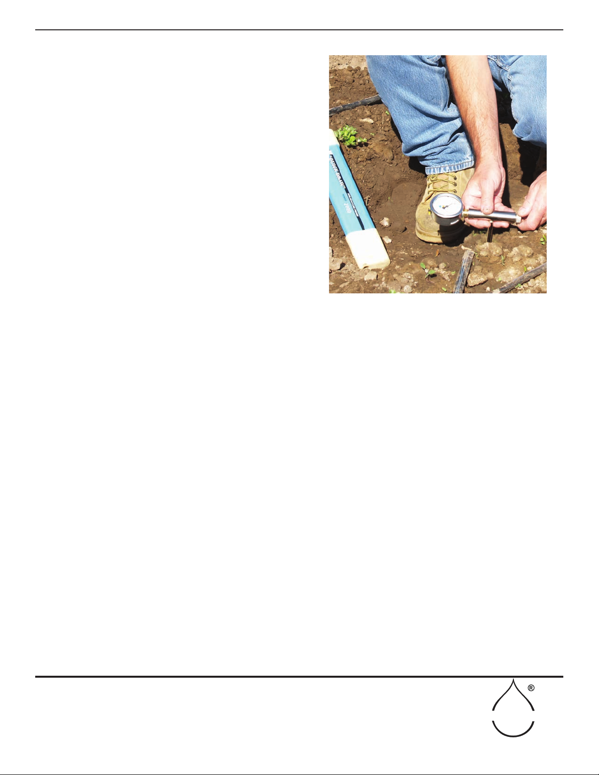
MAKING A SOIL MOISTURE MEASUREMENT (cont.)
(Figure 20)
MAKING A SOILMOISTURE READING – METHOD
ONE- with an example.
1.) Insert the probe in the ground and wait one minute then
note the reading – tap on the gauge occasionally.
Say our example yields 20 centibars.
2.) Take the reading and multiply it by 1.5
20 x 1.5 = 30.
3.) Use the null knob to dial in this new reading by turning
counter-clockwise.
Make it read 30 centibars.
4.) Wait another 15-30 second for wet soil (like 30) and
maybe 2 to 5 minutes in very dry (like 50) or clay soils.
Yawn.
5.) Observe if the needle moves to a higher or lower num-
ber – remember to tap on the gauge occasionally.
Say our needle drops to 28 centibars
6.) We are now bracketing in an know that the actual value
is in-between 28 and 20 so we pick the midpoint of 24 and
wait another 15-30 seconds also remembering to tap the
gauge a few times..
Use the null knob clockwise to go from 28 to 24 – tap on the gauge a couple of times.
7.) Say our needle climbs to 25. We know the real value is now between 25 and 28. One more dial should do it
and 26 is the dialing number. Wait and tap…………………….
Counter clockwise rotation increases from 25 to 26. The suspension is killing me!
8.) Say our needle moves up from 26-27 in 30 seconds while tapping the gauge.
Bingo – the answer is 27 cb for that location and depth.
ANOTHER EXAMPLE – METHOD TWO with an example
1.) Insert the probe in the ground and immediately dial 40 cb by rotating the null knob counter clockwise. Then
wait one minute tapping the gauge. As soon as we see the needle move in either direction we will make our next
move.
Say the needle move up from 40 cb to 40.5 cb.
2.) Immediately move our needle from 40 cb to 50 cb by rotating the null knob counter clockwise and wait 1-5
minutes to see if the gauge moves in either direction tapping on the gauge occasionally.
Say our needle moves from 50 cb to 50.5 cb.
3.) Immediately move our needle from 50 cb to 60 cb by rotating the null knob counter clockwise and wait 1-5
minutes to see if the gauge moves in either direction tapping on the gauge occasionally.
Say our needle moves down from 60 to 59.5
4.) We can now start the bracketing procedure in-between 50.5 cb and59.5 cb 55 cb being the best candidate rotat-
ing the null knob clockwise with waiting and tapping the gauge.
Say our needle goes up from 55 to 55.5.
5.) One more bracket point and one more wait should do it we pick 57.5 cb we rotate the null knob counter clock-
wise from 55.5 cb to 57.5 cb.
Drum roll while we wait …………………… the needle goes to 58 cb.
6.) 58 cb is declared our reading for that location and depth.
If, after the rst adjustment, the pointer continues to move up to a higher rather than a lower reading, you should
immediately move the pointer approximately 10 centibars higher and observe the pointer movement. If it contin-
ues to move up to a higher value, advance the pointer an additional 10 centibars. Once you reach a level where the
14
SOILMOISTURE EQUIPMENT CORP.
P.O. Box 30025, Santa Barbara, CA 93105 U.S.A.
Telephone 805-964-3525 - Fax No. 805-683-2189
www.soilmoisture.com - sales@soilmoisture.com
SOILMOISTURE
It has been our experience that accurate, reliable moisture readings can be made within
a few minutes at any one given location. In general, the readings can be made more
quickly when soil suction levels are in the low range than when they are in the high
range.
No problems in measurement will be encountered in sandy or sandy-loam soils. In the
event you are making measurements in extremely heavy clay soils, more time than
normal will be required to reach equilibrium because of the extremely slow movement
of water through this type of soil.
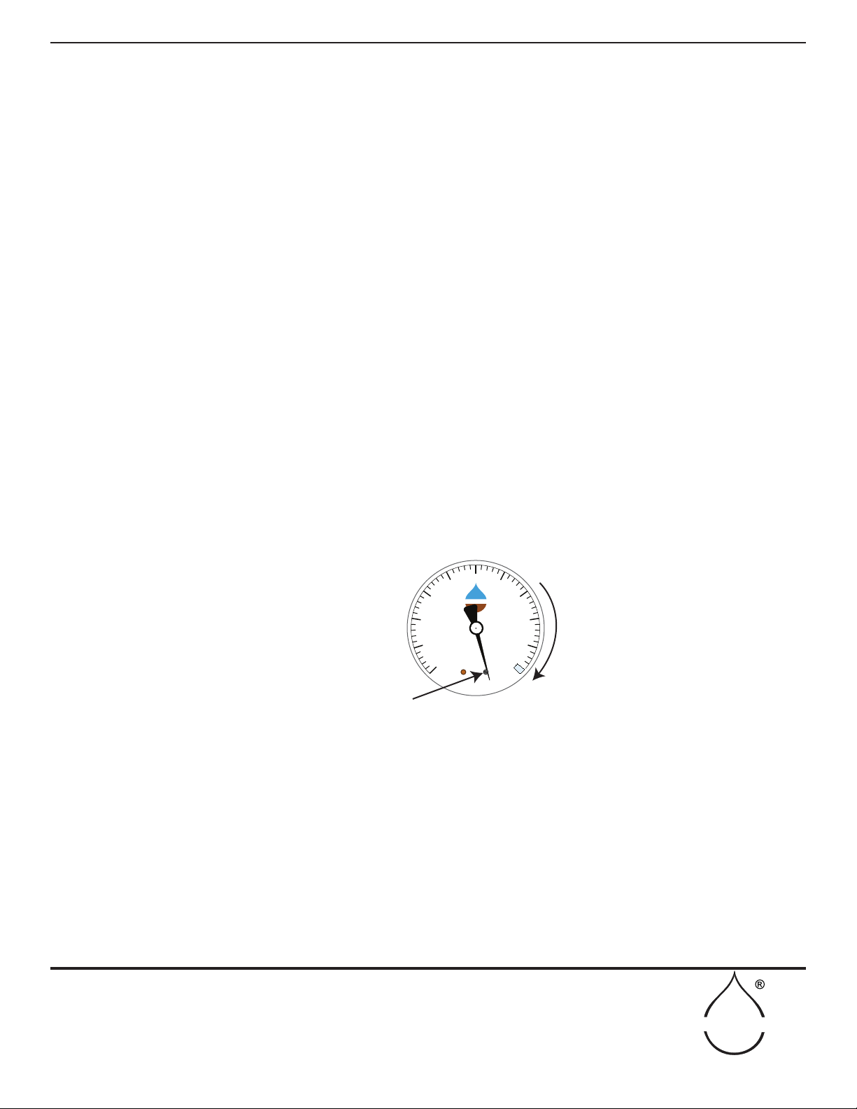
CAUTION!
In wet clay soils, the plastic soil itself can make an airtight closure around the sensing
tip as the Probe is being pushed into the soil. If this happens, pressure can be built up
in the Probe by the air trapped in front of the Probe. Since this air is sealed by the wet
clay soil, a high air pressure can develop as the Probe is pushed further and further into
the soil.
To detect such a condition, observe the dial pointer when pushing the Probe down
into the soil. If the pointer moves below the zero mark and touches the pin, pressure is
DIAL GAUGE
PRESSURE BUILD-UP
CAUTION!
MAKING A SOIL MOISTURE MEASUREMENT (cont.)
Figure 21 - Reading of pressure build up
CENTIBARS OF SOIL
SUCTION
www.soilmoisture.com
90
80
70 60 50 40
30
20
10
0
DRY
WET
100
D
O
N
O
T
F
R
E
E
Z
E
SOILMOISTURE
PIN
DIAL GAUGE
PRESSURE
BUILD UP
pointer starts to move back down, you have “bracketed” the reading, and adjustments
can be made, as described above, to arrive at the correct value.
In many moist soils, the Probe will come to equilibrium very quickly without any ap-
preciable adjustment of the Null Knob.
Through experience in using the Probe in your soils, you will soon be able to esti-
mate the nal dial gauge reading by the speed the pointer moves after insertion of
the Probe. It is best to minimize the use of the Null Knob to limit disturbing the soil
moisture conditions being measured.
After making a reading, the Soilmoisture Probe should be wiped free of surplus cling-
ing soil and immediately returned to the Carrying Case so the sensing tip remains
moist by being in contact with the water storage sponge, with the dial gauge reading
zero. When making eld measurements, if the soil suction value exceeds the highest
operating value corresponding to your elevation, the Probe should not be left in the
soil for extended periods.
Soil moisture values can vary considerably within a given area because of differences
in root action, drainage and exposure. For this reason, it is desirable to make several
readings in a given area in order to fully evaluate the soil moisture conditions.
15
SOILMOISTURE EQUIPMENT CORP.
P.O. Box 30025, Santa Barbara, CA 93105 U.S.A.
Telephone 805-964-3525 - Fax No. 805-683-2189
www.soilmoisture.com - sales@soilmoisture.com
SOILMOISTURE
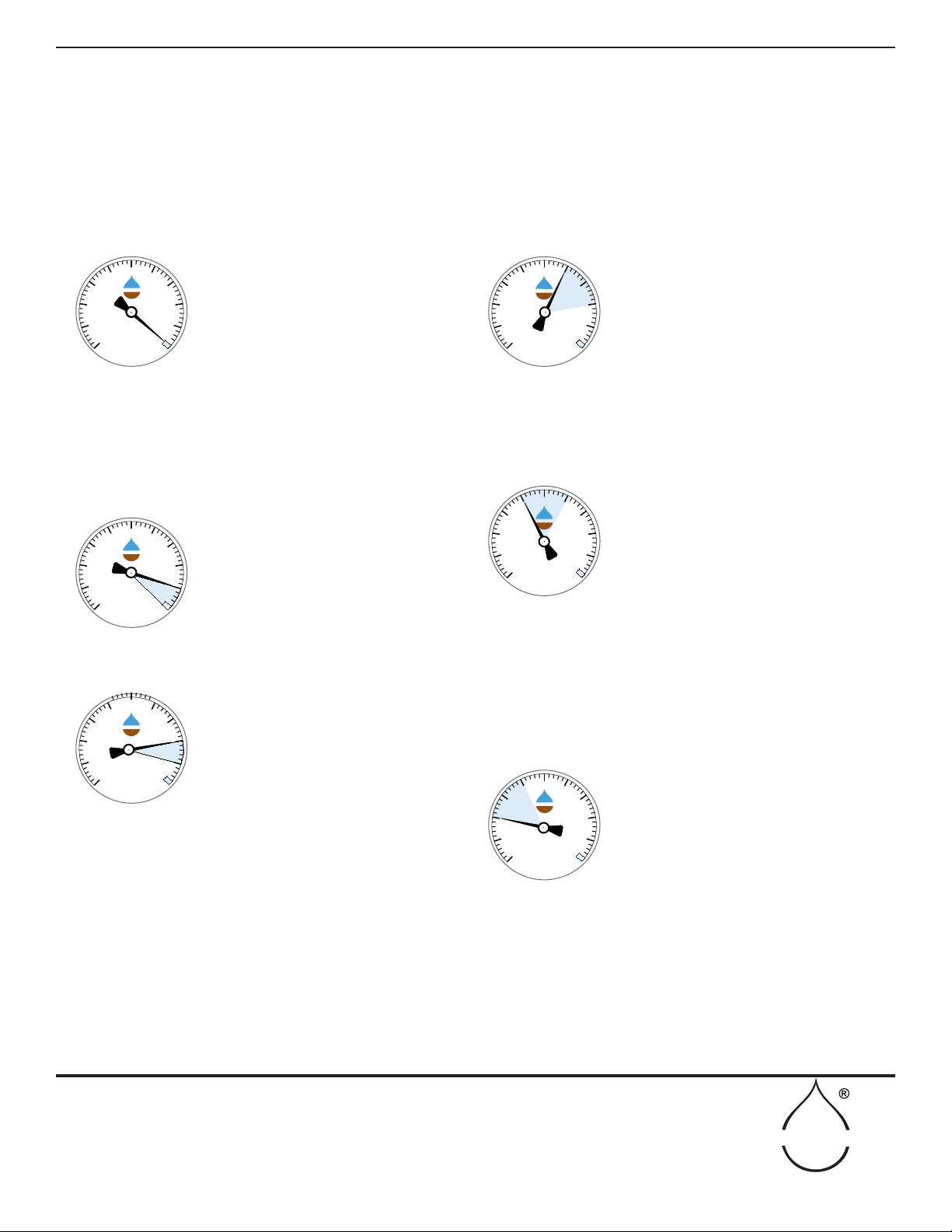
ZERO:
0-10 CENTIBARS:
10-20 CENTIBARS:
20-40 CENTIBARS:
40-60 CENTIBARS:
60-80 CENTIBARS:
CENTIBARS OF SOIL
SUCTION
SOILMOISTURE EQUIPMENT CORP
Santa Barbara, CA USA
90
80
70 60 50 40
30
20
10
0
DRY
WET
100
D
O
N
O
T
F
R
E
E
Z
E
SOILMOISTURE
CENTIBARS OF SOIL
SUCTION
SOILMOISTURE EQUIPMENT CORP
Santa Barbara, CA USA
90
80
70 60 50 40
30
20
DRY
WET
100
10
0
D
O
N
O
T
F
R
E
E
Z
E
SOILMOISTURE
CENTIBARS OF SOIL
SUCTION
SOILMOISTURE EQUIPMENT CORP
Santa Barbara, CA USA
90
80
70 60 50 40
30
20
DRY
WET
100
10
0
D
O
N
O
T
F
R
E
E
Z
E
SOILMOISTURE
CENTIBARS OF SOIL
SUCTION
SOILMOISTURE EQUIPMENT CORP
Santa Barbara, CA USA
90
80
70 60 50 40
30
20
DRY
WET
100
10
0
D
O
N
O
T
F
R
E
E
Z
E
SOILMOISTURE
CENTIBARS OF SOIL
SUCTION
SOILMOISTURE EQUIPMENT CORP
Santa Barbara, CA USA
90
80
70 60 50 40
30
20
DRY
WET
100
10
0
D
O
N
O
T
F
R
E
E
Z
E
SOILMOISTURE
CENTIBARS OF SOIL
SUCTION
SOILMOISTURE EQUIPMENT CORP
Santa Barbara, CA USA
90
80
70 60 50 40
30
20
DRY
WET
100
10
0
D
O
N
O
T
F
R
E
E
Z
E
SOILMOISTURE
A gauge reading of zero means the
surrounding soil is completely saturated
with water, regardless of the type of soil.
Zero readings can be expected after a
heavy rain or deep irrigation. If the zero
reading persists after a long period of
time, there will be oxygen starvation to
plant roots and development of diseases.
A persistent zero reading after irrigation
indicates poor drainage conditions which
should be investigated and corrected.
Gauge readings in the range of 0-10 cb
indicated a surplus of water for plant
growth. Water held by the soil in this
range drains off within a few days. Persis-
tent readings in this range indicate poor
drainage conditions which should be
corrected to obtain healthy plant growth.
Gauge readings in the range of 10-20cb
indicate that there is ample moisture and
also air in the soil for healthy plant growth
in all types of soils. This range is often
referred to as the “field capacity” range
for soils, which means that the soil has
reached its “capacity” and cannot hold
anymore water for future plant growth.
When soils are at “field capacity”, any
additional water that is added drains out
of the root zone within a day or two before
it can be used by the growing plant. If
irrigation has been in process, it should
be stopped when gauge drops to this
level, since any further additional water
will be quickly drained from the root zone
and wasted, carrying with it valuable
fertilizer.
Available moisture and aeration good
for plant growth.
HEAVY CLAY SOILS: No irrigation
required.
MEDIUM TEXTURED SOILS: No
irrigation required.
SANDY SOILS: Irrigation started for
coarser sandy soils in the 20-30 cb
range. For finer sandy soils in the
30-40 cb range.
Available moisture and aeration are
good for plant growth in finer textured
soils.
HEAVY CLAY SOILS: No irrigation
required.
MEDIUM TEXTURED SOILS: Irriga-
tion started in this range. The finer the
texture the higher the reading before
start of irrigation.
SANDY SOILS: Too dry. Hot windy
conditions can force soil suction to
high reading quickly and damage
plants.
Readily available moisture scarce,
except in heavy clay soils.
HEAVY CLAY SOILS: Start of irriga-
tion desirable as soil suction values
reach 70-80 cb.
MEDIUM TEXTURED SOILS:Too dry.
Hot, windy conditions can force soil
suction to high reading quickly and
damage plants.
SANDY SOILS: Too dry. Damage to
plants will occur before irrigation can
be applied.
GAUGE READINGS (cont.)
building up (Fig. 21). Stop pushing and pull the Probe up to relieve the pressure. Then push the Probe down and pull
up again in short strokes to enlarge the hole in the sensing tip area, which will prevent the entrapment of air. Then
push the Probe to full depth and make a reading.
IRRIGATION SCHEDULING
16
SOILMOISTURE EQUIPMENT CORP.
P.O. Box 30025, Santa Barbara, CA 93105 U.S.A.
Telephone 805-964-3525 - Fax No. 805-683-2189
www.soilmoisture.com - sales@soilmoisture.com
SOILMOISTURE
The QuickDraw can be used for different types of measurements; for spot checks and measures from a permanent
location:
a) Use for spot checks to determine the wetting area from drippers or to determine if there is enough moisture for
germination in the seed-bed. Simply use the coring tool to shape the hole at the depth of measurement. Insert the
QuickDraw and wait for the reading to become steady.
b) One can make routine measurements at a given depth in the same hole each time measurements are necessary.
Use ½˝ PVC as a riser from the depth to measure to the soil surface. Place the pipe at the depth of measurement,
minus an inch or so. Use an end cap or aluminum foil to prevent irrigation from a sprinkler from entering the pipe
and wetting the soil at depth instead of from surface inltration. Remove the cap and insert the QuickDraw and
force the ceramic tip into the soil at the depth of measurement. Make your measurement as normal. Re-cap the riser
pipe when nished.
Use the null knob to adjust the vacuum in the tensiometer to your set point for irrigation particular to
the soil and crop being monitoring. The advantage of adjusting the null knob is to quickly determine if the set point
has been reached or not and the question "is it time to irrigate?" can be easily determined.
If the vacuum dial gauge exceeds the set point, then it is denitely time to schedule the irrigation. If the vacuum
dial gauge decreases in vacuum, then the soil is more moist than your set point for irrigation and your decision is
to not irrigate.
Using this approach, allows the user to rapidly make management decisions. Absolute, at equilibrium, measure-
ments are not required using this approach.
ROUTINE MEASUREMENTS
The Model 2900F Soilmoisture Probe is particularly
valuable in determining moisture conditions in potted
plants such as those in commercial buildings or nurs-
eries. The Probe responds quickly in planting mixes
used in potted plants and usually can be pushed direct-
ly down into the root zone without coring a hole. Its
portability eliminates vandalism, which is not true of
xed moisture measuring instruments. With the Mod-
el 2900F, a thoughtful plan can be developed to keep
maintenance and water costs to a minimum.
For frequent evaluation of moisture conditions in large irrigated elds, the use of sev-
eral Probes can speed up the work. As an example, an agricultural consultant who
programs irrigation for his client can insert a number of Probes in a eld without tak-
ing immediate readings. When the crop is high, the Probes would be agged with a
red cloth on a wire stake so they can be easily found. The consultant can then make
his other crop observations. After completing his other work, he would return to pick
up the Soilmoisture Probes. By this time, the Probes would have reached equilibrium,
and the readings would be quickly noted.
Using a number of
Probes at the same
time
Potted Plants
(Figure 37)

17
SOILMOISTURE EQUIPMENT CORP.
P.O. Box 30025, Santa Barbara, CA 93105 U.S.A.
Telephone 805-964-3525 - Fax No. 805-683-2189
www.soilmoisture.com - sales@soilmoisture.com
SOILMOISTURE
The successful operation of the Model 2900F Soilmoisture Probe is due to its structural
rigidity and the fact that the air has been almost completely removed from the water
and the internal structure of the Probe. For these reasons, any small amount of move-
ment of water through the porous ceramic sensing tip will result in a substantial change
of the vacuum level within the Probe. This very responsive action coupled with the use
of the Null Knob, results in only a small disturbance to the water lms in the surround-
ing soil, which are being measured. Hence, accurate measurements of soil suction can
be made quickly.
If air is present in the unit, then a substantial amount of water must ow through the
wall of the porous ceramic sensing tip to change the vacuum level within the Probe. The
air within the Probe expands as the pressure is reduced (centibar reading in-creased),
which causes a larger amount of water to move in and out of the surrounding soil. The
result is a less responsive movement of the pointer on the dial gauge, a “spongy” ac-
tion of the Null Knob, and a longer time to obtain an accurate soil moisture measure-
ment. The response time is dened as the time required for the dial pointer to drop
from 50 centibars to 10 centibars when the porous ceramic sensing tip is plunged into
a container of water.
Over a period of many months or years, the pores in the ceramic sensing tip have a
tendency to become clogged with deposits, which decreases the permeability of the
ceramic. Such clogging will, of course, slow down the response time of the Probe. If
the Probe has been carefully lled with water to remove all accumulated air, and the re-
sponse time is still in excess of 2 seconds, it is advisable to replace the porous ceramic
sensing tip with a new one (see page 17).
Substantial change in
the vacuum level
Lack of reponse from
gauge
TROUBLESHOOTING
50 centibars can not be
reached
If, at any time, the operation of the Probe appears to be “spongy” and excessive time
is required to make a soil suction reading, simply remove the Probe from the Carrying
Case. Wipe the porous sensing tip with an absorbent tissue and turn the Null Knob so
the pointer on the dial gauge registers 50 centibars. Then plunge the sensing tip of the
Probe into a container of water and note the time required for the pointer to drop from
50 centibars to 10 centibars. If it is appreciably more than one second, it indicates that
there is air accumulated within the Probe. To remove the air from the Probe and restore
the fast response time, rell the Probe with water as described under “Initial Filling”,
page 2.
If the porous ceramic sensing tip as been cracked during use, it will permit air to enter
the system. A very ne crack not be readily observed. Usually under these circum-
stances, it is not possible to obtain a reading of 50 centibars to conduct the response
time test. If a dial reading of 50 centibars cannot be reached by drying the sensing tip
and turning the Null Knob, there is too much air in the system, and there may also be
a crack in the sensing tip. To replace the porous ceramic sensing tip, see the section on
this.

18
SOILMOISTURE EQUIPMENT CORP.
P.O. Box 30025, Santa Barbara, CA 93105 U.S.A.
Telephone 805-964-3525 - Fax No. 805-683-2189
www.soilmoisture.com - sales@soilmoisture.com
SOILMOISTURE
If the porous ceramic sensing tip has been broken or cracked during use or if the pores of the ceramic have become
clogged resulting in too long Probe response time, it can be readily replaced with a new one. The O-ring seals must
also be replaced when you replace the ceramic sensing tip.
To replace the sensing tip, rst remove the slotted cap nut at the end of the Probe. Use a large screwdriver that ts
the slot in the cap nut, or the small pointer-adjusting screwdriver can be used, by inserting the side of the screw-
driver in the slot in the nut (Fig. 22).
When facing the end of the Probe, turn the cap nut COUNTERCLOCKWISE to loosen it. Completely remove the
cap nut, the porous ceramic sensing tip, and the two O-ring seals at either end of the sensing tip. When you remove
the parts, be sure that the smooth surfaces on the cap nut and on the stem of the Probe, where the O-rings seat, are
not scratched or marred. It is essential that these surfaces are kept smooth to assure a complete vacuum seal when
the new sensing tip is installed. Clean off any accumulated corrosion from the stem of the Probe.
The O-ring seals, porous ceramic sensing tip and slotted cap nut are arranged (see Fig. 23) in the same manner as
they t on to the stem of the Probe. (Continued on next page)
Figure 22 - Removing the slotted cap nut Figure 23
REPLACING THE POROUS CERAMIC SENSING TIP

19
SOILMOISTURE EQUIPMENT CORP.
P.O. Box 30025, Santa Barbara, CA 93105 U.S.A.
Telephone 805-964-3525 - Fax No. 805-683-2189
www.soilmoisture.com - sales@soilmoisture.com
SOILMOISTURE
Figures 24 through 28 show the successive operations in
mounting the parts on the stem of the Probe.
In the nal assembly operation, screw on the slotted cap nut
and tighten it securely with a screwdriver. The slotted cap
screw should be tightened as far as it will go. Parts have been
carefully machined so the O-ring seals are properly squeezed
when the slotted cap nut is screwed completely on until it
seats on the end of the Probe stem. The O-rings make a vac-
uum-tight seal between the brass surfaces of the Probe stem
parts and the ends of the porous ceramic sensing tip.
The ends of the porous ceramic sensing tip have been ma-
chined smooth to assure a vacuum-tight seal. When you
mount the porous ceramic sensing
tip on the Probe, make sure that the sensing tip is not scratched
or chipped.
The Porous Ceramic Sensing Tip is supplied with a tapered
conguration. The taper matches the taper of the Coring Tool.
The taper assures better contact with the soil, which increases
sensitivity and speed of response.
When you replace the tip, special care must be taken to see
that the “top” arrow marked on the tip points in the direction
as shown in Fig. 29.
After replacing the tip, ll the Probe as described in “Initial
Filling” (see page 7).
Replacing the Porous Ceramic Sensing Tip (cont.)
Figure 24
Figure 25
Figure 26
Figure 27
Figure 28 Figure 29
20
SOILMOISTURE EQUIPMENT CORP.
P.O. Box 30025, Santa Barbara, CA 93105 U.S.A.
Telephone 805-964-3525 - Fax No. 805-683-2189
www.soilmoisture.com - sales@soilmoisture.com
SOILMOISTURE
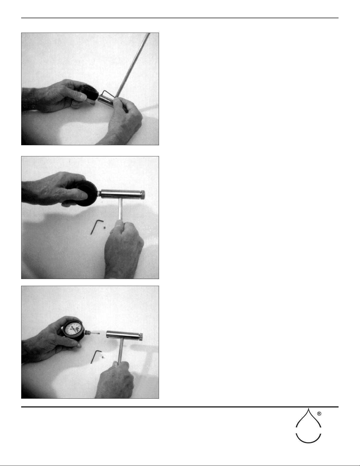
Replacing The Dial Gauge
If the dial gauge has been mechanically damaged making it
inoperative, it may be replaced in the eld.
First remove the socket head set screw from the handle,
as shown in Fig. 30. This is an “Allen” head set screw that
accepts a 3/32” size Allen wrench, which is supplied in the
Accessory Kit.
Then grasp the dial gauge rmly, as shown in Fig. 31, and turn it
counterclockwise until it is free from the handle.
Fig. 32 shows the dial gauge removed from the handle.
The internal connecting tube usually remains in the dial
gauge. Carefully pull out the internal connecting tube from the
dial gauge.
Figure 30
Figure 31
Figure 32
Table of contents
Other Soilmoisture Equipment Laboratory Equipment manuals


Popular Laboratory Equipment manuals by other brands

Ametek
Ametek VersaSTAT MC Hardware manual

Agilent Technologies
Agilent Technologies G1701EA Familiarization guide

Thermo Scientific
Thermo Scientific MATRIX PLATEMATE 2x3 user manual

Buchi
Buchi Rotavapor R-220 Operation manual

Thermo Scientific
Thermo Scientific VARIOMAG MINI 07 operating manual

Nippon Genetics
Nippon Genetics FASTGENE ELECTRONIC PIPETTE-200 manual

PASCO
PASCO EM-6720 instruction sheet

Buchi
Buchi HydrolEx H-506 Operation manual

Lumascape
Lumascape PowerSync PS installation instructions

Agilent Technologies
Agilent Technologies 11970 Series user guide

Micromeritics
Micromeritics Mercury QuikVac 090 Operator's manual

WPI
WPI NANOLITER2020 instruction manual


