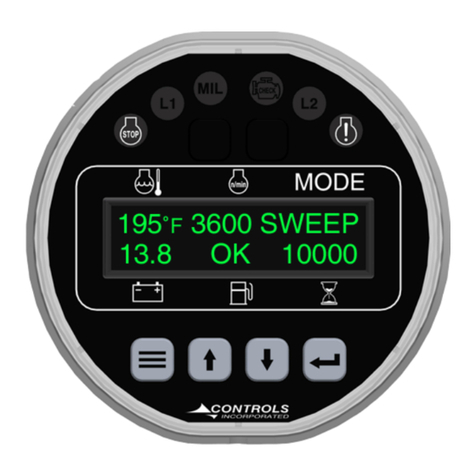
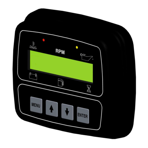
Controls iMech Series User manual

Product Manual
iMech Series
Microprocessor-BasedEngineManagement System
For Mechanical Engines
Part Number: C3M-100-AS
Revision: 1.2
______________________________________________________________________________________________________________________________________
Copyright Controls, Inc.
P.O. Box 368 • Sharon Center, OH 44274
Phone 330.239.4345 • Fax 330.239.2845 • www.controlsinc.com

CONTROLS, INCORPORATED
C O N T R O L S Y S T E M S & S O L U T I O N S
- 1 -
1) Introduction
1.1 The C3M-100-AS is a sealed microprocessor-based engine control system for industrial engines. It is based
on the Controls, Inc. iMech series controller platform with a Freescale 8 bit processor.
1.2 The product is packaged into a water tight, polycarbonate enclosure for maximum durability. The controller
is plug & play with a sealed bulkhead engine connector incorporated into the case.
1.3 The digital display is 1”H x 4”W with two rows of 16 characters. Character height is approximately ½”. The
display has automatic temperature compensation for optimal viewing across the entire operating
temperature range of –20C to +70C. Backlight intensityis also adjustable. An extreme temperature option
is available, which extends the operating temp to –45C to +85C and the storage temp to –55C to +95C.
1.4 The unit monitors all critical engine functions and has full time display of Oil Pressure, Engine Temperature,
Engine Speed, Battery Voltage, Fuel Level and Engine Hours.
1.5 Analog Input is available for fuel level monitoring or can be used as a digital switch input. OEM
Programming is available for other parameter monitoring.
1.6 Digital Flex Input is available for Auto Start.
1.7 The controller with corresponding amber or red LED illuminations above the digital displaymonitors engine
safetyalarms. Text messages are displayed automatically.
iMech™ C3M-100-AS

CONTROLS, INCORPORATED
C O N T R O L S Y S T E M S & S O L U T I O N S
- 2 -
2) Interface
2.1 Display–The backlit digital display is 1”H x 4”W with two rows of 16 characters. Character height is
approximately ½”.
2.2 DisplayParameters –The six full-time displayparameters are:
∙ Water Temperature ∙ BatteryVoltage
∙ Engine RPM ∙ Fuel Level
∙ Oil Pressure ∙ Engine Hours
2.3 Menu & Enter Buttons –To access and scroll menus.
2.4 Up & Down Buttons –For menu navigation and engine speed if configured.
2.5 Amber (Prealarm) LED and Red (Alarm) LED located above the digital display.
2.6 Harness Connector –Ampseal 14 pin, White

CONTROLS, INCORPORATED
C O N T R O L S Y S T E M S & S O L U T I O N S
- 3 -
3) Enclosure
3.1 Sealed Polycarbonate Enclosure
3.2 O-Ring Seal
3.3 Four 10-32 Brass bosses used to mount unit to sheet metal or vibration isolators.
3.4 Two Hole Require if mounting directlyto sheet metal

CONTROLS, INCORPORATED
C O N T R O L S Y S T E M S & S O L U T I O N S
- 4 -
4) Panel Operation
4.1.1 Power Up –Unit performs a power up self-test. Initialization screen displays firmware version. LEDs
are illuminated for operation verification.
4.1.2 Preheat Cycle –If programmed, the unit will energize the preheat circuit. A countdown message will
be displayed.

CONTROLS, INCORPORATED
C O N T R O L S Y S T E M S & S O L U T I O N S
- 5 -
4.1.3 Acquiring Information –Panel begins monitoring sensor inputs. Values are displayed. If no
information is available due to a sensor not being connected, the display shows dashed lines.
4.1.4 Typical Operating Screen –After the operator has started the engine using the keyswitch, the
panel displays and updates engine information continuously. Parameters such as oil pressure and
engine temperature can be configured to be displayed in Metric or English units. Fuel level is
displayed in percentage.

CONTROLS, INCORPORATED
C O N T R O L S Y S T E M S & S O L U T I O N S
- 6 -
4.1.5 Engine Warning –When the iMech detects a parameter is outside of its normal operating range, the
amber LED will illuminate and the value will flash on the display. These settings are user
programmable.
4.1.6 Engine Shutdown –When the iMech detects a parameter has exceeded its normal operating range
for a period of time, the red LED will illuminate and a shutdown will occur. A text message will be
displayed on the LCD screen and remain there until the power is cycled. These settings are user
programmable.

CONTROLS, INCORPORATED
C O N T R O L S Y S T E M S & S O L U T I O N S
- 7 -
4.1.7 Alarm Logging –Anytime a warning or shutdown condition occurs, the panel willstore the event in
non-volatile memory. The last 16 events willbe stored with a running time stamp for reference.
Clearing of the log requires entering the password.
4.1.8 Operation Logging –Anytimethe engine is started or stopped, the panel will log the event. The last
16 events will be stored with a running time stamp for reference. Clearing of the log requires entering
the password.

CONTROLS, INCORPORATED
C O N T R O L S Y S T E M S & S O L U T I O N S
- 8 -
4.1.9 Throttle Operation –When using the iMech to control engine speed, a third partygovernor or other
actuator device must be used.
4.1.9.1 Hi - Lo: LCD Messages of “Throttle Hi” and “Throttle Low” will be used to indicate if the assigned
relay has closed. An open / closed signal will be generated by the panel. 5-ampmax.
4.1.9.2 Momentary: Directional arrows will be used to indicate when the operator has pressed the Up or
Down arrows buttons. Assigned relays will close upon activation. 5-amp max.
Up Arrow
Down
Arrow

CONTROLS, INCORPORATED
C O N T R O L S Y S T E M S & S O L U T I O N S
- 9 -
5) External Connectors
5.1 C3M-100 Module Connector - The C3M-100 module is connected to the internal wiring harness
via a 14-pin TYCO plug. To add additional wires to any available position, please use pins
770854-1. Individual 12” wires with crimped pins are available from CI. P/N 70-0302
Pin
Function
Pin
Function
1
Fuel Solenoid (10 Amp)
8
MPU+ or Tach Signal
2
Engine Temp Sender
9
Battery Positive Common
3
Battery Positive Common
10
Auto Position Detect*
4
Auto Crank Signal* (10 Amp)
11
Switched Power to C3M
5
Pre Heat Signal (5 Amp)
12
Battery Negative
6
N/O of Relay1** (Ground Signal)
13
Fuel Level Sender
7
Oil Press Sender
14
Flex Digital Input
‘* When used in auto start configurations. Do not apply power to 11 when auto mode is desired.
** Common tied to battery minus.
AMPSEAL
776262-1

CONTROLS, INCORPORATED
C O N T R O L S Y S T E M S & S O L U T I O N S
- 10 -
6) Controller Menus
6.1 The control panel has menus to view engine and controller parameters. Thesemenus are accessible via the
four-button pad located on the face of the control panel.
6.2 Menu Rings
Menu Category
Use
Operation Event Log
View last 16 events
Alarms Event Log
View last 16 alarms
Auto Start Configuration*
Set time delays and cycles.
Sender Configuration
Set units, senders, and limits.
Module Configuration
Set logic, relays, inputs, hours
Calibration
Set speed signal to engine.
Module Information
Viewmodel and firmware version
*When used in auto start configurations.
6.3 Menu Access & Navigation
6.3.1 Accessing Menus
1. Press and hold the MENU key & simultaneously press the ENTER key.

CONTROLS, INCORPORATED
C O N T R O L S Y S T E M S & S O L U T I O N S
- 11 -
6.3.2 Navigation
1. Press MENU to select the next menu category.
2. Press UP to view or edit the specific screen(s) in the category.
3. Press Down to step through logged events.
4. Use the UP and DOWN keys to move among the screens in the category.
5. Press MENU at any time within a category to jump back to the inner ring.
Stepping through menu categories
Entering into category
Viewing logged events

CONTROLS, INCORPORATED
C O N T R O L S Y S T E M S & S O L U T I O N S
- 12 -
6.3.3 Password Entry
The password screen is provided to restrict the edit of sensitive values to authorized personnel.
Not entering a password permits viewing, but no editing of restricted values. Upon encountering
the password screen, a series of dashes will be displayed. To enter the password: [4345].
Entering password
1. Press ENTER to begin editing. The password zeroes will be bracketed.
2. Use the UP and DOWN keys to set the first (leftmost) digit, as you would for a cylinder
combination lock.
3. Press ENTER to freeze that digit and move to the next one on the right.
4. Repeat steps 2 and 3 until all four digits have been set. After the final digit is set, the brackets
automatically disappear.
5. Press the UP key to proceed to the next screens.
If the correct password was entered earlier, navigating back over the password entry screen will
show the password as a row of stars. The password approval state is retained as long as the
panel is powered up.
6.3.4 Editing
Some screens permit parameter changes.
1. Press ENTER to start editing. The value on the screen will be surrounded by brackets. On
password-protected screens, brackets appear only when the correct password was entered
earlier.
2. Use the UP and DOWN keys to adjust the value. In the case of a selection list, the various
possible selections will be shown in a ring. In the case of a variable number, press the
appropriate key to step up/down. For larger changes, press and hold the UP or DOWN key.
(The value will step faster as the key is held down. Stepping will stop when preset value limits
are reached or the key is released.)
3. Press ENTER to save the new value. The brackets will disappear.
4. To skip the edit and retain the old value, press MENU instead of ENTER.
Leaving during editing will abandon the edit, and the old value will be retained.

CONTROLS, INCORPORATED
C O N T R O L S Y S T E M S & S O L U T I O N S
- 13 -
6.3.5 Exiting
1. Press and hold the MENU key & simultaneously press the ENTER key.
Exiting the menus
Exiting has no effect on the password approval. To clear the approved password state,
power cycle the panel.

CONTROLS, INCORPORATED
C O N T R O L S Y S T E M S & S O L U T I O N S
- 14 -
7) Module Configuration
Allows the user or OEM to set up the proper behavior and functionalityof the module. Options include the
following. Defaults in [ ].
7.1 Preheat Time –Programmable in minutes and seconds. [0.00]
7.2 Hour Meter –Programmable in hours. [0]
7.3 Clear Op Log –Yes, [No]
7.4 Clear Alarm Log –Yes, [No]
7.5 Throttle Type –[None], Hi/Low, Momentary
7.6 Relay 1 Function –[None], Prealarm, Alarm, Engine Run, Switch Trip, Fuel/Run, Preheat, Throttle
B0, Throttle B1, StartWarning, Crank*
7.7 Relay 1 Polarity- [Positive], Invert
7.8 Relay 1 Init State –[Off], On
7.9 Relay 2 Function –None,Prealarm, Alarm, Engine Run, Switch Trip, [Fuel/Run], Preheat, Throttle
B0, Throttle B1, StartWarning, Crank*
7.10 Relay 2 Polarity- [Positive], Invert
7.11 Relay 2 Init State –Off, [On]
7.12 Relay 3 Function –None, Prealarm, Alarm, Engine Run, Switch Trip, Fuel/Run, [Preheat], Throttle
B0, Throttle B1, StartWarning, Crank*
7.13 Relay 3 Polarity- [Positive], Invert
7.14 Relay 3 Init State –[Off], On
7.15 Relay 4 Function –[None], Prealarm, Alarm, Engine Run, Switch Trip, Fuel/Run, Preheat,Throttle
B0, Throttle B1, StartWarning, Crank*
7.16 Relay 4 Polarity- [Positive], Invert
7.17 Relay 4 Init State –[Off], On
7.18 Input (Flex Digital) Normally –[Open], Closed
7.19 Trip Action –[Nothing], Prealarm, Alarm
7.20 Input Check –[Never], Always, Run
7.21 Trip Message –[None], LowWater, Low Oil, Hi Temp,Low Press, Custom.
7.22 Top Line Message –Write your own.
7.23 Bottom Line Message –Write your own.
7.24 LCD Contrast –0-100%, [55%], Automatic adjustment based on temperature.
7.25 LCD Backlight –0-100%, [100%]
*When used in auto start configurations.

CONTROLS, INCORPORATED
C O N T R O L S Y S T E M S & S O L U T I O N S
- 15 -
8) Sender Configuration
Allows the user or OEM to set up the proper sender types and engine safety limits of the module. Options
include the following. Defaults in [ ].
8.1 Press & Temp Units –Metric, [English]
8.2 Sender Check Bypass–5 –60 Sec, [10]
8.3 Fuel Sender–VDO, [S-W]
8.4 Fuel Level Check –Never, Always, [Run]
8.5 Low Fuel Prealarm –0-100% [20]
8.6 Low Fuel Alarm –0-100% [1%]
8.7 Fuel Alarm Delay- 0 –100 Sec, [5]
8.8 Low Oil Press Check –Never, Always, [Run]
8.9 Low Oil Press Prealarm –0-100 PSI [15]
8.10 Low Oil Press Alarm –0-100 PSI [10]
8.11 Oil Press Alarm Delay- 0 –100 Sec, [5]
8.12 Temp Check –Never, Always, [Run]
8.13 Low Temp Prealarm –0 - 300 F [0]
8.14 Low Temp Alarm ––0 - 300 F [0]
8.15 High Temp Prealarm –0 - 300 F [220]
8.16 High Temp Alarm ––0 - 300 F [230]
8.17 Temp Alarm Delay- 0 –100 Sec, [5]
8.18 Battery Volts Check –[Never], Always, Run
8.19 Low Bat Prealarm –0.0 –40.0 VDC [12.0]
8.20 Low Bat Alarm –0.0 –40.0 VDC [0.0]
8.21 High Bat Prealarm - 0.0 –40.0 VDC [15.0]
8.22 High Bat Alarm –0.0 –40.0 VDC [40.0]
8.23 Bat Alarm Delay- 0 –100 Sec, [5]
8.24 Over Speed Check –[Never], Always, Run
8.25 Over Speed Alarm –0-5000 PSI [3000]
9) Calibration
Allows the user or OEM to trim specific parameters of the module. Defaults in [ ].
9.1 Battery Trim –0-1000mV, [500mV]
9.2 Flywheel Teeth –1-200, [100]
9.3 Auto Set Teeth? -Yes, [No]

CONTROLS, INCORPORATED
C O N T R O L S Y S T E M S & S O L U T I O N S
- 16 -
10) Warranty
CONTROLS, INC. is herein called “Seller”. The person, firm or corporation to whom or
which the sale is made is herein called “Buyer”. Seller warrants to the Buyer that all
products furnished under this order will conform to Seller’s specification, drawings as
described in its current catalog or quotation and will be free from defects in materials
and workmanship. Seller must approve other special requirements asked for by the
Buyer in its purchase order in writing. Parts replaced or repaired in the warranty period
shall carry the unexpired portion of the original warranty. The foregoing is subject to the
provisions that in no case will the total warranty period extend beyond twelve (12)
months from date seller ships equipment from point of sale.
The Liability of Seller hereunder is limited to replacing or repairing at Seller’s factory
any part or parts which have been returned to the Seller and which are proved by buyer
as defective or not conforming to Seller’s specifications, drawings or other written
descriptions, accepted by Seller, provided that such part or parts are returned by the
buyer within thirty (30) days after such defect is discovered. All items returned to Seller
for repair or replacement must be sent freight prepaid to its factory. Buyer must obtain
Seller’s Return Merchandise Authorization # prior to returning items. The above
conditions must be met if warranty is valid. Seller will not be liable for any damage
done by unauthorized repair work, or unauthorized misapplication in non-suitable
environment.
In no event shall the Seller be liable for loss, damage, or expense directly or indirectly
arising from the use of the units, or from any other cause, except as expressly stated in
the warranty. Seller makes no warranties, express or implied, including any warranty
as to merchantability of fitness for a particular purpose or use. Seller is not liable for
and buyer waives any right or action it has or may have against seller for any
consequential or special damages arising out of any breach of warranty, and for any
damages buyer may claim for damage to any property or injury or death to any person
arising out of its purchase or the use, operation or maintenance of the product. Seller
will not be liable for any labor subcontracted or performed by buyer for preparation of
warranted item for return to Seller’s factory or for preparation work for field repair or
replacement. The Seller will not consider invoicing of Seller for labor either performed
or subcontracted by buyer as a liability. This warranty shall be exclusive of any and all
other warranties express or implied and may be modified only by a writing signed by an
officer of the Seller. With respect to accessories supplied by Seller, but manufactured
by others, there is no warranty of any kind, express or implied, and specifically there is
no warranty of merchantability or fitness, except as may be set forth in any warranty the
manufactures have made to Seller and which can be passed to the Buyer.
Other manuals for iMech Series
1
Table of contents
Other Controls Laboratory Equipment manuals
Popular Laboratory Equipment manuals by other brands

Raven
Raven Sidekick Pro ISO Installation & operation manual

Waters
Waters Andrew+ quick start guide

Harvard Bioscience
Harvard Bioscience BTX Tweezertrodes user manual

CEM
CEM Razor Installation and operation instructions

Cuisinart
Cuisinart CS-7 SERIES user manual

Parker Research Corp
Parker Research Corp DA-1500 operating instructions