Soilmoisture Equipment 3000F01 User manual
SOILMOISTURE EQUIPMENT CORP.
P.O. Box 30025, Santa Barbara, CA 93105 U.S.A.
Telephone 805-964-3525 - Fax No. 805-683-2189
sales@soilmoisture.com - www.soilmoisture.com
SOILMOISTURE
OPERATING
INSTRUCTIONS
Plant Water Status Console February 2011
Model 3000F01
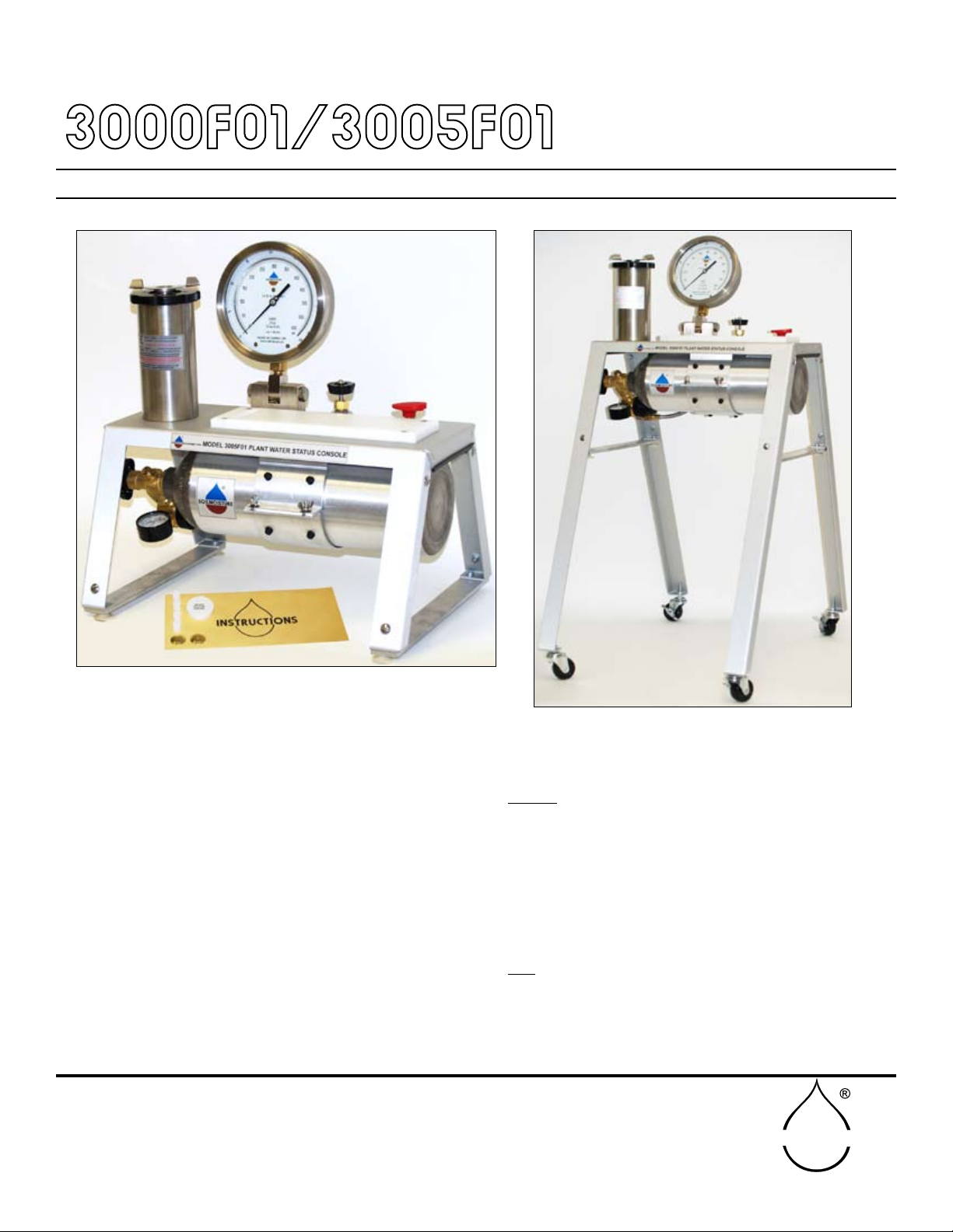
The Plant Water Status Console, Model 3000F01, is supplied without the compressed gas cylinder or the pres-
sure regulator, but does come with a 5-foot long, exible, high pressure (3,000 psi working pressure) stainless
steel connecting hose to connect to your pressure source. One end of the connecting hose is sealed to the
pressure inlet of the console. The other end can be tting with standard 1/4-inch pipe ttings to connect to your
regulated pressure source. We recommend you use brass pipe and tube ttings that have a 3,000 psi working
pressure. The regulated pressure that you supply to the console must not exceed the maximum pressure reading
of the pressure readout gauge of the console. For standard units this pressure is 600 psi.
Model 3005F01
The Plant Water Status Console, Model 3005F01, is supplied with a compressed gas cylinder and connected
pressure regulator for eld operation. The pressure regulator has been set at the factory for the maximum operat-
ing pressure of the unit which, for standard units, is 600 psi.
Fig. 01 - Model 3005F01 Plant Water Status Console - Table top
Fig. 02- Model 3005F01 Plant Water Status Console
(EXTENSION LEGS ATTACHED)

SOILMOISTURE EQUIPMENT CORP.
P.O. Box 30025, Santa Barbara, CA 93105 U.S.A.
Telephone 805-964-3525 - Fax No. 805-683-2189
sales@soilmoisture.com - www.soilmoisture.com
SOILMOISTURE
2
Soilmoisture Equipment Corp. (SEC) warrants all products manufactured by SEC to be free from defects
in materials and workmanship under normal use and service for twelve (12) months from the date of
invoice provided the section below has been met.
Soilmoisture Equipment Corp. (SEC) is not liable for any damages, actual or inferred, caused by misuse
or improper handling of its products. SEC products are designed to be used solely as described in these
product operating instructions by a prudent individual under normal operating conditions in applications
intended for use by this product.
WARRANTY & LIABILITY
TABLE OF CONTENTS
UNPACKING
The Plant Water Status Console was thoroughly tested before shipment. When packed, it was in per-
fect working order. Unpack with care being sure to remove all packing material. Follow the instructions
carefully in order to ensure long, trouble-free service.
Any damage found upon receipt should be reported immediately to the transport carrier for
claim. It is important to save the shipping container and all evidence to support your claim.
Be sure to read all operating instructions thoroughly before operating the unit.
The Plant Water Status Console comes fully assembled. See page 4 for instructions on how to as-
semble the leg extensions for laboratory use.
As with any pressure system, use reasonable caution. Be sure all valves are off before trans-
porting. Do not lean directly over the specimen holder. Leave it to a qualied technician to do
the repairs. Have the unit serviced at least once a year. DOT standards on aluminum pressure
vessels require hydrostatic testing every 5 years.
CAUTIONS & WARNINGS
Unpacking .............................................................................................................................................2
Cautions & Warnings..............................................................................................................................2
Warranty & Liability.................................................................................................................................2
General specications............................................................................................................................3
Theory of operation................................................................................................................................3
Acquaint Yourself with the parts.............................................................................................................4
Leg Extension Assembly...........................................................................................................5
Speciman holder and Pressure Vessel.....................................................................................5
Gauge.......................................................................................................................................6
Prep Board................................................................................................................................7
Valve Controls........................................................................................................................7-8
How to use and/or operate unit.........................................................................................................9-11
General care and maintenance............................................................................................................12
How to replace the compressed gas cylinder..........................................................................12
How to rell the compressed gas cylinder...............................................................................13
Helpful hints during normal use............................................................................................................14
Troubleshooting....................................................................................................................................14
Minor Adjustments................................................................................................................................14
Use and application of product options................................................................................................15
Specimen Holders and Grommets..................................................................................................15-18
Notes....................................................................................................................................................19
Replacement parts and accessories list.........................................................................................20-21

3
SOILMOISTURE EQUIPMENT CORP.
P.O. Box 30025, Santa Barbara, CA 93105 U.S.A.
Telephone 805-964-3525 - Fax No. 805-683-2189
sales@soilmoisture.com - www.soilmoisture.com
SOILMOISTURE
22 cubic foot aluminum DOT-3AL aluminum cylinder with CGA-580 tting rated for 2216 psi – requires •
hydrostatic testing every 5 years.
Single stage, step-down regulator set to 600 psi at the factory (can be reset by user if necessary).•
Standard pressure vessel 7˝, 0.5 liter volume, 2.4 kg, 40 or 80 bars. Cam lock. Specimen holder •
with safety valve. Internal diameter 2.73˝ with vertical useable height 5.837˝.
12˝ and 20˝ vessels also available. 12˝, 3.8 kg, 1 liter volume, 10.837” height. 20”, 6.3 kg, 1.8 liter, •
19.837˝ height.
All vessels 2.73˝ diameter and rated for 80 bars with cam lock and safety valve features. Made of •
stainless steel for a lifetime of use.
6˝ scientic test gauge with beryllium copper movement and stainless steel case, ¼ of 1% full scale •
accuracy and the highest quality you can buy for many years of service.
600 psi gauge, 40 bars. Subdivisions 2 psi, 0.2Bars, 20 kPa.•
Resolution ½ a division. Dual scale psi + kPa, Parallax mirror and adjustable needle to re-zero if •
necessary.
1500 psi gauge, 80 bars. Subdivisions 10 psi, 0.5 Bars, 50 kPa.•
Resolution ½ a division. Dual scale psi + kPa, Parallax mirror and adjustable needle to re-zero if •
necessary.
THEORY OF OPERATION
GENERAL SPECIFICATIONS
The roots of a plant are using reverse osmotic forces to overcome the matrix potential of the soil. The
stomates on the leaves of a plant are transpiring at different rates throughout the day. The resulting
tension in the xylem column can be measured using a plant water status console device.
The petiole of a leaf or stem is placed in a rubber grommet so the leaves are inside the pressure chamber
and the stem is outside at atmospheric pressure. By pressurizing the chamber and watching the point
where the sap oozes out of the stem at atmospheric pressure the 2 forces are in balance – the reading
on the gauge and the tension in the xylem column. This value can vary from the bottom to the top of the
plant and at different times of the day due to temperature, humidity, sunlight, and wind. By stressing
the plant, better crops can be produced and water use better managed.
4
SOILMOISTURE EQUIPMENT CORP.
P.O. Box 30025, Santa Barbara, CA 93105 U.S.A.
Telephone 805-964-3525 - Fax No. 805-683-2189
sales@soilmoisture.com - www.soilmoisture.com
SOILMOISTURE
44
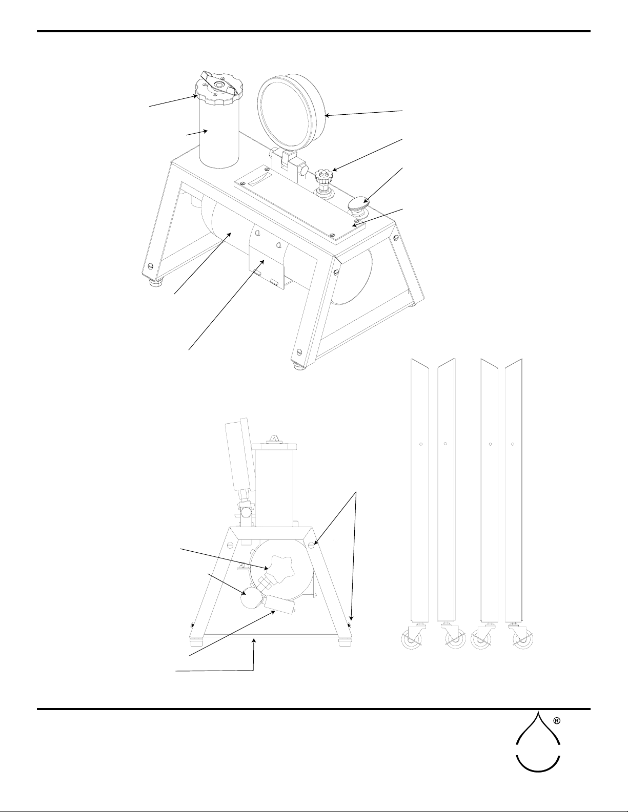
AQUAINT YOURSELF WITH THE PARTS
SIDE VIEW Model 3005
PRESSURE GAUGE
COMPRESSED
GAS CYLINDER
(Model 3005 only)
PREPARATION
BOARD
3-WAY
CONTROL VALVE
METERING VALVE
TEST GAUGE
PRESSURE VESSEL
SPECIMEN
HOLDER
TANK
MOUNT BRACKET
(Model 3005 only)
Model 3005 PLANT WATER STATUS CONSOLE
SEALING VALVE
PRESSURE REGULATOR
SUPPORT BAR LEG EXTENSIONS (2 FRONT / 2 BACK)
ROUND HEAD BOLTS
(FOR LEG EXTENSION
ASSEMBLY - 8 PER UNIT)
Fig. 03 - Plant Water Status Console primary parts
5
SOILMOISTURE EQUIPMENT CORP.
P.O. Box 30025, Santa Barbara, CA 93105 U.S.A.
Telephone 805-964-3525 - Fax No. 805-683-2189
sales@soilmoisture.com - www.soilmoisture.com
SOILMOISTURE
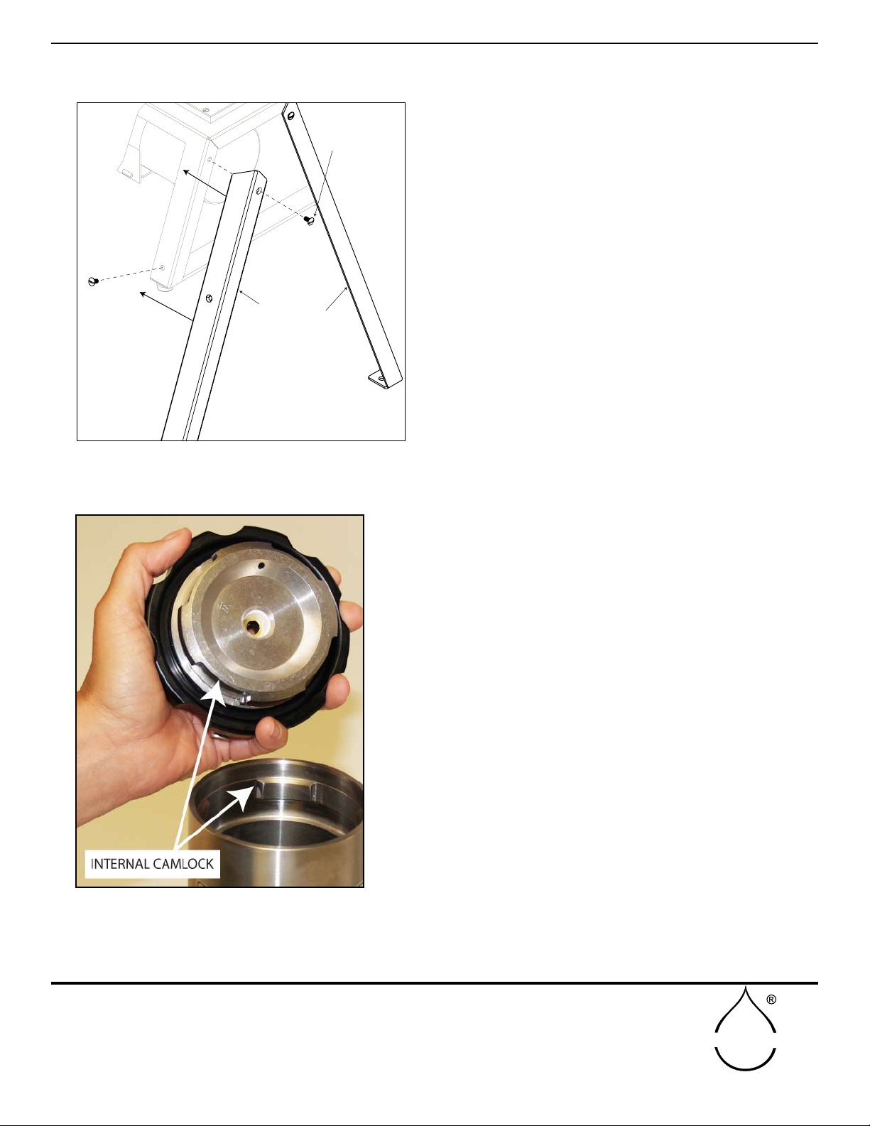
Assembly may require assistance depending on the size of
pressure vessel and total weight of unit.
(Fig.04)
Unscrew round head bolts on each leg. (Total of 8 bolts 1.
included solely for the leg extensions)
Gently lay unit on front or back side. The unit may be 2.
resting on the pressure vessel. Although the pressure
vessel is bolted securely on the chassis, be careful not
to add any additional pressure.
Match legs to bolt holes. Re-insert bolts through bolt3.
holes and tighten.
Gently turn unit over and repeat steps 2 & 3 with the nal 4.
two legs.
The specimen holder is held securely in place with four internal
cams at the top of the vessel. The vessel’s high pressure gas inlet
is in the center of the vessel base. Remove the specimen holder by
turning the closing cap counterclockwise 45° and pulling the holder
upward (Fig. 05). To insert the specimen holder for a run, turn the
specimen holder 45° clockwise to lock it in place.
When the specimen holder is removed the rst time, it may require
considerable force. The “O” ring used to make the pressure seal
tends to “seize” to the metal surface if it is allowed to remain in
the compressed position for a considerable time. To minimize this
problem, apply a thin coat of light grease, such as stopcock grease
or Vaseline, to the “O” ring. Then, after the specimen holder is re-
moved for the rst time, it will enter and close.
AQUAINT YOURSELF WITH THE PARTS (cont.)
LEG EXTENSION ASSEMBLY
SPECIMEN HOLDER AND PRESSURE VESSEL
ROUND HEAD BOLTS
(2 EACH LEG)
FRONT LEG EXTENSION
BACK LEG EXTENSION
Fig. 04 - Leg extension assembly
Fig. 05- Specimen Holder

6
SOILMOISTURE EQUIPMENT CORP.
P.O. Box 30025, Santa Barbara, CA 93105 U.S.A.
Telephone 805-964-3525 - Fax No. 805-683-2189
sales@soilmoisture.com - www.soilmoisture.com
SOILMOISTURE
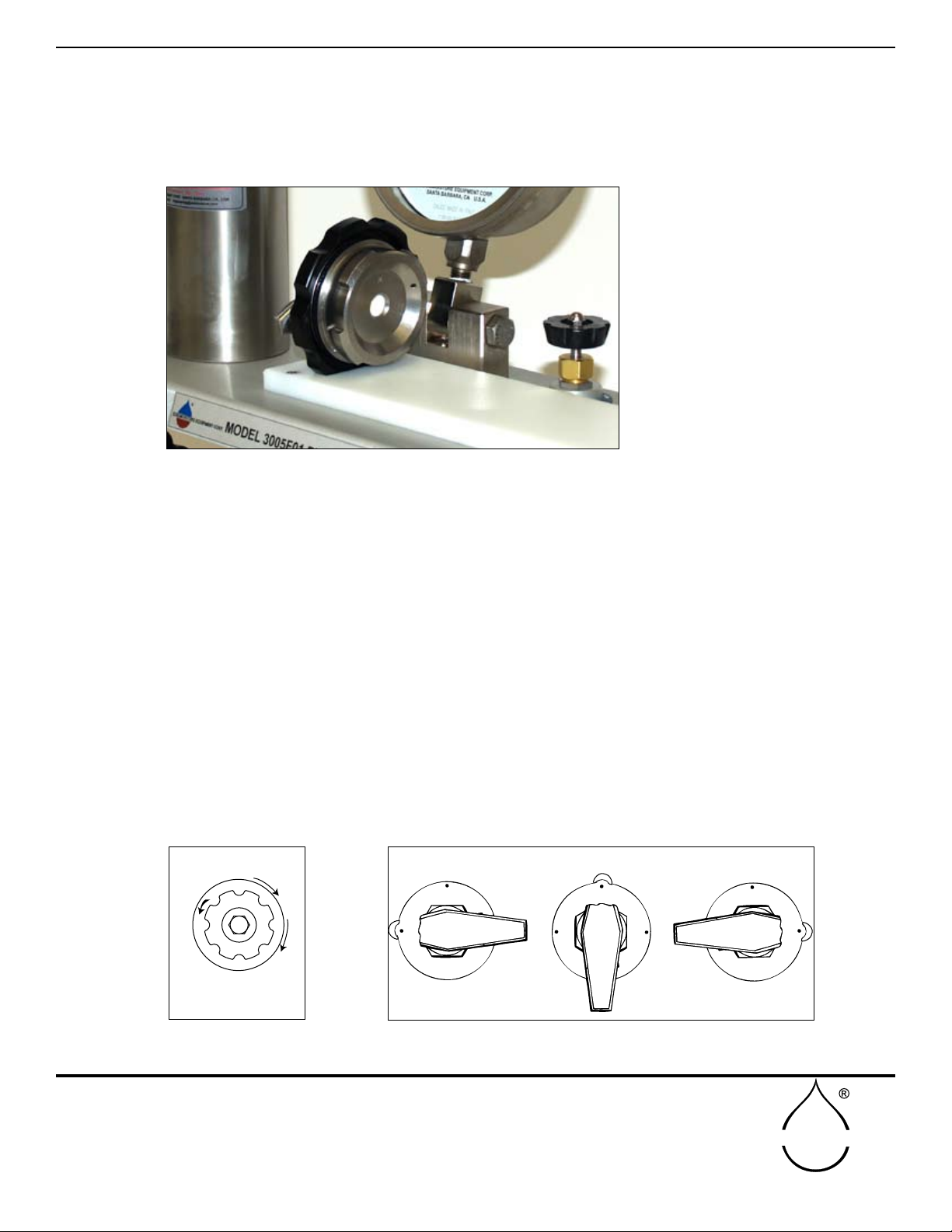
The fail safe valve (Fig. 6), in line with the pressure vessel cams, prevents build up of pressure in the
pressure vessel unless the specimen holder is completely locked in place.
The sealing knob (Fig. 6) on the specimen holder actuates the collet-type closure that pressure seals
the specimen and sealing sleeves during a run. Turning the sealing knob clockwise seals the specimen.
Turning counterclockwise releases the seal. (Sealing sleeves and grommets are discussed on pages
15-18.)
GAUGE
The 6 inch dial face, 1/4 +/- of 1% accuracy test gauge, graduated in both psi (pounds per square inch)
and in bars, indicates the pressure within the pressure vessel at all times. The swivel support base pro-
vides a detent to hold the gauge in two reading positions and one position for transport (Fig.07). A zero
pointer position adjusting screw is provided for zeroing the pointer in the event it is jarred out of place.
AQUAINT YOURSELF WITH THE PARTS (cont.)
Fig. 06- Specimen Holder
FAIL SAFE VALVE
SEALING KNOB
SEALING SLEEVE
GROMMET
Fig. 07- Test gauge with swivel base
7
SOILMOISTURE EQUIPMENT CORP.
P.O. Box 30025, Santa Barbara, CA 93105 U.S.A.
Telephone 805-964-3525 - Fax No. 805-683-2189
sales@soilmoisture.com - www.soilmoisture.com
SOILMOISTURE
The metering valve controls the rate at which pressure is built up in the pressure vessel. The valve is
usually adjusted so that the rate of pressure increase is in the range of 5-10 psi per second. Turning the
valve counterclockwise increases the rate of ow. During routine tests, this valve can be left at one xed
position to give uniform pressure building up on all samples. When the metering valve is closed (by
turning clockwise) care should be taken not to exert excessive closing force since this tends to damage
the valve seat and the long tapered valve which provides the sensitive gas ow control (Fig. 09).
The control valve directs the ow of gas into or out of the pressure vessel or seals the gas within the
pressure vessel (Fig. 10). When the control valve is in the “OFF” position, high pressure gas within the
pressure vessel is sealed in and no gas can enter or leave. When the control valve is in the “PRESSUR-
IZE” position, high pressure supply air from the pressure regulator ows through the metering valve,
through the control valve and into the pressure vessel. When the control valve is in the “EXHAUST”
position, the high pressure gas within the pressure vessel exhausts immediately to the atmosphere.
VALVE CONTROLS
PREPBOARD
The high density polyethylene preparation board provides a convenient cutting block for the prepara-
tion of leaf samples. The notch at the end holds the specimen holder during the loading operation to
minimize possibilities of damage (Fig. 08).
P
R
E
S
S
U
R
I
Z
E
O
F
F
P
R
E
S
S
U
R
I
Z
E
O
F
F
E
X
H
A
U
S
T
O
F
F
E
X
H
A
U
S
T
PRESSURIZE OFF EXHAUST
AQUAINT YOURSELF WITH THE PARTS (cont.)
Fig. 08- Specimen holder on prep board
Fig. 09- Metering valve settings
T
O
I
N
C
R
E
A
S
E
F
L
O
W
M
E
T
E
R
I
N
G
V
A
L
V
E
C
L
O
S
E
Fig. 10- Control valve settings
8
SOILMOISTURE EQUIPMENT CORP.
P.O. Box 30025, Santa Barbara, CA 93105 U.S.A.
Telephone 805-964-3525 - Fax No. 805-683-2189
sales@soilmoisture.com - www.soilmoisture.com
SOILMOISTURE
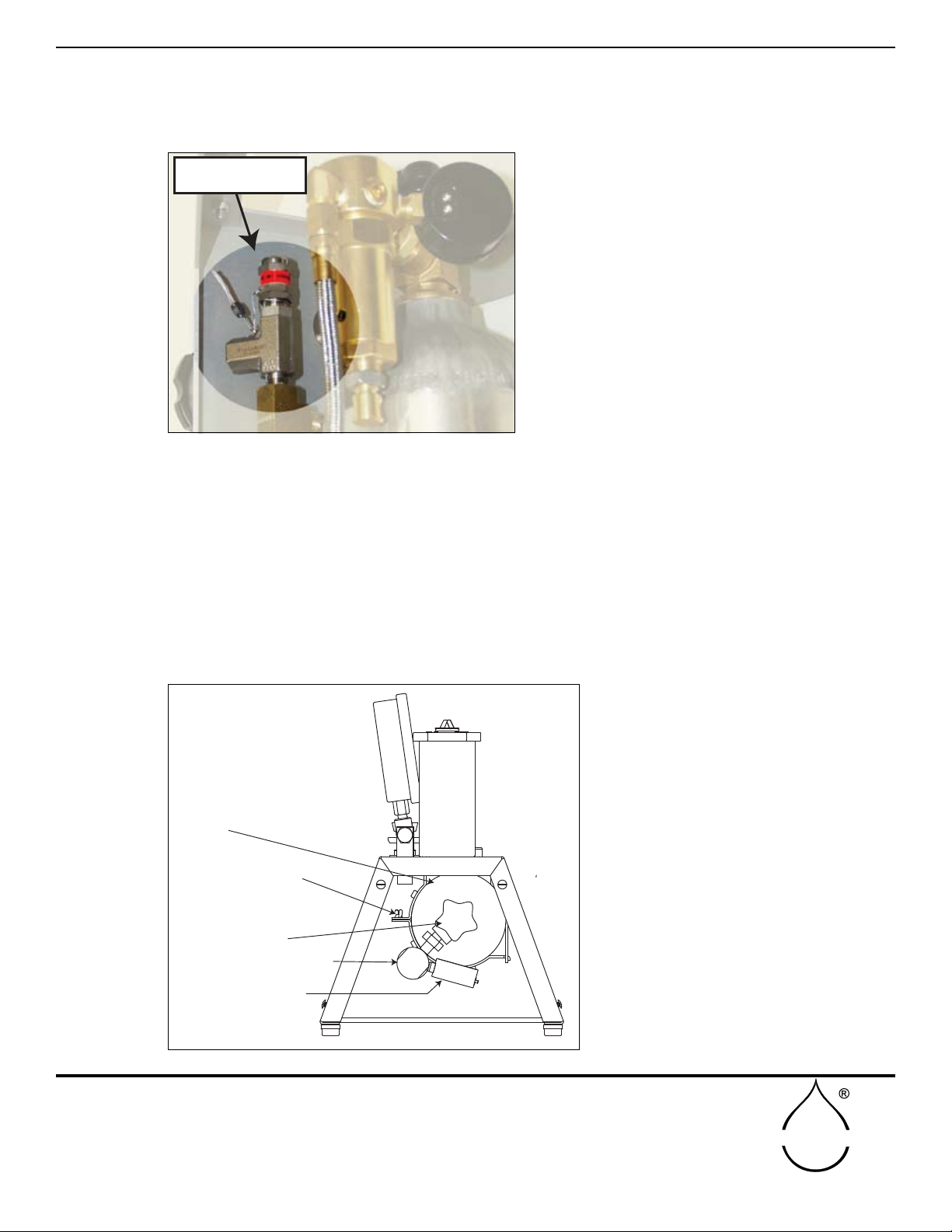
Underneath the panel a safety relief valve is incorporated in the system to prevent damage from any
excess buildup of pressure. The relief valve is set at the factory so that pressure will be released when
it exceeds the maximum operating range of the console (Fig. 11).
The pressure regulator is connected to the compressed gas cylinder. It can readily be removed for re-
placement or relling of the cylinder. The output pressure on the regulator has been set at the factory
at 600 psi for standard consoles.
The small pressure gauge, screwed into one of the ports of the regulator indicates the pressure within
the compressed gas cylinder and is used as a guide to indicate when the cylinder needs relling
(Fig. 12).
The rellable 2,216 psi, 22 cubic feet capacity, compressed gas cylinder is held securely by the tank
mounting bracket beneath the chassis. When empty, it can be lled in place without removing it from the
chassis. The sealing valve at the end of the tank should be kept closed (turn clockwise) except when
the console is in use.
AQUAINT YOURSELF WITH THE PARTS (cont.)
Fig. 11 - Safety relief valve
Fig. 12 - Parts under chassis
SAFETY RELIEF VALVE
(BOTTOM OF UNIT VIEW)
PRESSURE GAUGE
SEALING VALVE
PRESSURE REGULATOR
TANK MOUNTING
BRACKET
TANK

9
SOILMOISTURE EQUIPMENT CORP.
P.O. Box 30025, Santa Barbara, CA 93105 U.S.A.
Telephone 805-964-3525 - Fax No. 805-683-2189
sales@soilmoisture.com - www.soilmoisture.com
SOILMOISTURE
Step 1
Close the metering valve, turning clockwise (Fig. 09).
Step 2
The rellable 2,216 psi, 22 cubic feet capacity, compressed gas cylinder is held securely by the bottle
bracket beneath the chassis. When empty, it can be lled in place without removing it from the chassis.
The sealing valve at the end of the tank should be kept closed (turn clockwise) except when the console
is in use (Fig. 12).
Step 3
Open compressed gas cylinder sealing valve, by turning counterclockwise (Fig. 12).
Step 4
Remove specimen holder from pressure vessel, as described earlier, and place in notch of sample
preparation board (Fig. 08).
Step 5
Select sample leaf to run.
On initial run to check the unit and to acquaint yourself with its operation, you can substitute a round
rod for the leaf sample in order to seal the specimen holder. A nail, rivet, dowel pin, or round 1/8-inch to
1/4 inch in diameter may be used. If the diameter to be sealed is less than 1/8-inch, select the sup-port
washer with the 9/64-inch hole. If the diameter to be sealed is greater than 1/8 inch select the support
washer with the 1/4 inch hole. Next, select one of the rubber sealing sleeves that best ts the stem
diameter.
Step 6
Arrange the sealing sleeve on the stem, as shown,
and insert into the specimen holder, as shown. Turn
the sealing knob clockwise until the compressing
grommet squeezes the sealing sleeve sufciently
around the stem to hold it securely (Fig. 13).
Step 7
Holding the specimen holder by the closing cap, in-
sert the leaf sample into the pressure vessel and
then push the specimen holder down into place in
the pressure vessel. Pushing down with both thumbs
(one thumb on either side of the specimen holder, is
a good way to secure the specimen holder in place.)
Then, turn the specimen holder 45° clockwise, us-
ing the closing caps to lock it under the cams of the
pressure vessel.
Step 8
Tighten the sealing knob further, if necessary, to
be sure that the sealing sleeve is sealing properly
around the stem.
HOW TO USE AND/OR OPERATE THE UNIT
Fig. 13 - Stem insertion into the specimen holder
10
SOILMOISTURE EQUIPMENT CORP.
P.O. Box 30025, Santa Barbara, CA 93105 U.S.A.
Telephone 805-964-3525 - Fax No. 805-683-2189
sales@soilmoisture.com - www.soilmoisture.com
SOILMOISTURE
Step 9
Turn the control valve to the PRESSURIZE position (Fig. 10).
Step 10
Slowly open the metering valve, by turning it counterclockwise, and observe the pressure buildup on
the readout gauge (Fig. 09). Adjust valve until rate of increase is in the range of 5-10 psi per second or
at the rate you desire for the test.
Step 11
To stop the build up of pressure within the vessel at any time, simply turn the control valve (Fig.10) to
the “OFF” position. To resume build up of pressure, turn the control valve slowly to the “PRESSURIZE”
position.
Note: if the control valve is turned quickly to the “PRESSURIZE” position after an interruption in pres-
sure build up, as above, there will be a quick jump in pressure of a few pounds within the pressure
vessel. This is caused by the high pressure gas that builds up in the connecting tube between the
metering valve and the control valve while the control valve is in the “OFF” position. When the control
valve is opened quickly, this small volume of high pressure gas (supply pressure -600 psi) discharges
immediately into the pressure vessel. Thereafter, the metering valve limits the ow.
Step 12
The build up of pressure within the vessel can also be stopped or reduced at any time by turning the
metering valve in a clock-wise direction. Once you know the approximate value for the equilibrium
pressure for the plant specimen being tested, it is usually desirable to reduce the rate of pressure build
up as you approach the equilibrium pressure so that the equilibrium value can more accurately be
determined.
Step 13
As pressure builds up in the pressure vessel, carefully observe the cut end of the petiole of the sample.
(Fig. 14)
If you hear air escaping around the sealing area of the sam-
ple, or if the stem seems to be “extruding” or moving up out of
the sealing sleeve, simply tighten the sealing knob further to
exert higher sealing pressure to stop the leak or movement.
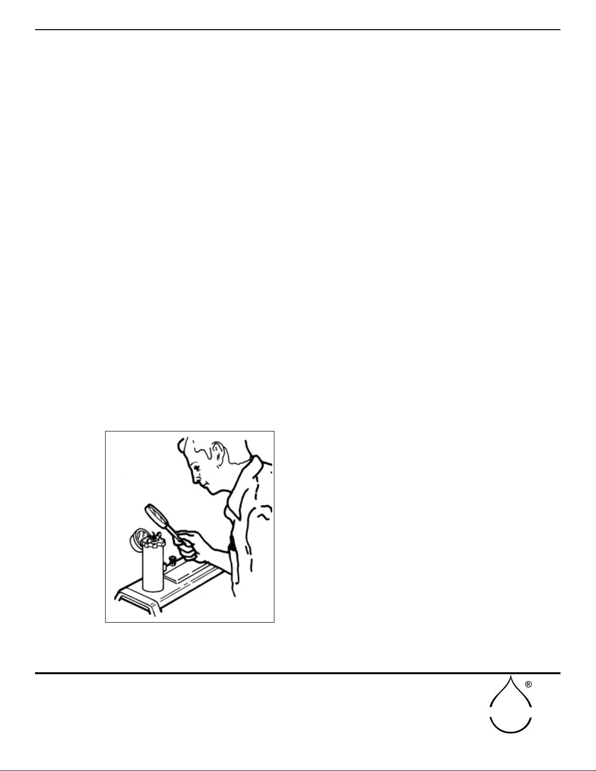
CAUTION: Never put your eye directly over the center
of the pressure vessel during a run. Always observe the
sample stem from the side. Remember you are dealing
with high pressures and it is possible that a sample -
such as an individual needle from a pine tree - can be
ejected from the holder. It is recommended that the end
of the cut petiole be observed through a low-power mag-
nifying glass. The glass will give a better view and also
offers protection for the eyes.
Step 14.
The equilibrium pressure for the individual sample is reached
when sap starts to ow from the exposed cut end of the sam-
ple.
Fig. 14 - Observing the cut petiole of the sample
HOW TO USE AND/OR OPERATE THE UNIT (cont.)

11
SOILMOISTURE EQUIPMENT CORP.
P.O. Box 30025, Santa Barbara, CA 93105 U.S.A.
Telephone 805-964-3525 - Fax No. 805-683-2189
sales@soilmoisture.com - www.soilmoisture.com
SOILMOISTURE
After the sample has been mounted in the Plant Water Status Console(PWSC), and during the initial
stages of the pressure build up within the PWSC, the cut end will appear relatively dry. However, when
the equilibrium pressure is reached, the end will slicken up and be shiny and wet in appearance as sap
starts to ow from the end of the sample. If pressure is further increased, small bubbles may be formed
and arise in the extruded sap.
The build up of pressure should be stopped immediately when the cut end of the sample starts to
slicken in appearance by the extrusion of sap. The pressure reading at this point is the equivalent to
the negative force with which the plant water is held within that particular sample. After the equilibrium
pressure has been reached, one can verify the pressure immediately by dropping the pressure in the
pressure vessel below the equilibrium value. When this is done, you will note that the sap stops owing
immediately, pulls back into the stem of the sample, and the cut surface acquires the relatively dry ap-
pearance again. The build up can then be resumed again at a slow rate until sap again begins to ow.
You will note that the second equilibrium obtained matches very closely the rst reading.
Step 15
After this equilibrium value, sometimes referred to as plant
water potential or plant water stress, has been determined
and noted, pressure in the pressure vessel is exhausted
through the control valve by turning it to the “EXHAUST”
position.
The exhausting gas will make an appreciable noise de-
pending upon the pressure in the extraction vessel. The
exhaust port is underneath the control panel (Fig. 15) and
bafed by the end castings that hold the leg. The exhaust-
ing gas presents no hazard to the operator.
Step 16
Remove the sample by loosening the sealing knob slightly when the specimen holder is still in the pres-
sure vessel. Then, turn the closing cap of the specimen holder 1/8 turn (45 °) in a counterclockwise
direction.
Pull the specimen holder, with the specimen still in place, directly up out of the pressure vessel. Further
release the sealing pressure on the specimen by turning the sealing knob counter-clockwise until the
specimen and sealing sleeve can be readily removed.
The thrust washer will tend to remain in place in the specimen holder and can be left there to accept a
subsequent sample.
Step 17
If no further samples are to be run, shut off the compressed gas cylinder sealing valve. Remaining high
pressure gas within the system beyond the storage tank valve can be cleared, if desired, by turning the
control valve to the “PRESSURIZE” position with the metering valve opened somewhat. Under these
conditions, the gas in the system beyond the storage tank will exhaust through the pressure vessel.
After exhausting the pressure, turn the control valve again to the ‘OFF” position.
EXHAUST PORT
Fig. 15 - Exhaust Port
HOW TO USE AND/OR OPERATE THE UNIT (cont.)
12
SOILMOISTURE EQUIPMENT CORP.
P.O. Box 30025, Santa Barbara, CA 93105 U.S.A.
Telephone 805-964-3525 - Fax No. 805-683-2189
sales@soilmoisture.com - www.soilmoisture.com
SOILMOISTURE
HOW TO REPLACE THE COMPRESSED GAS CYLINDER
The compressed gas cylinder can be easily replaced with a full
tank or the tank can be lled from a larger supply tank without
removing it from the console.
Step 1
Set the console on end and support it so that it doesn’t fall over.
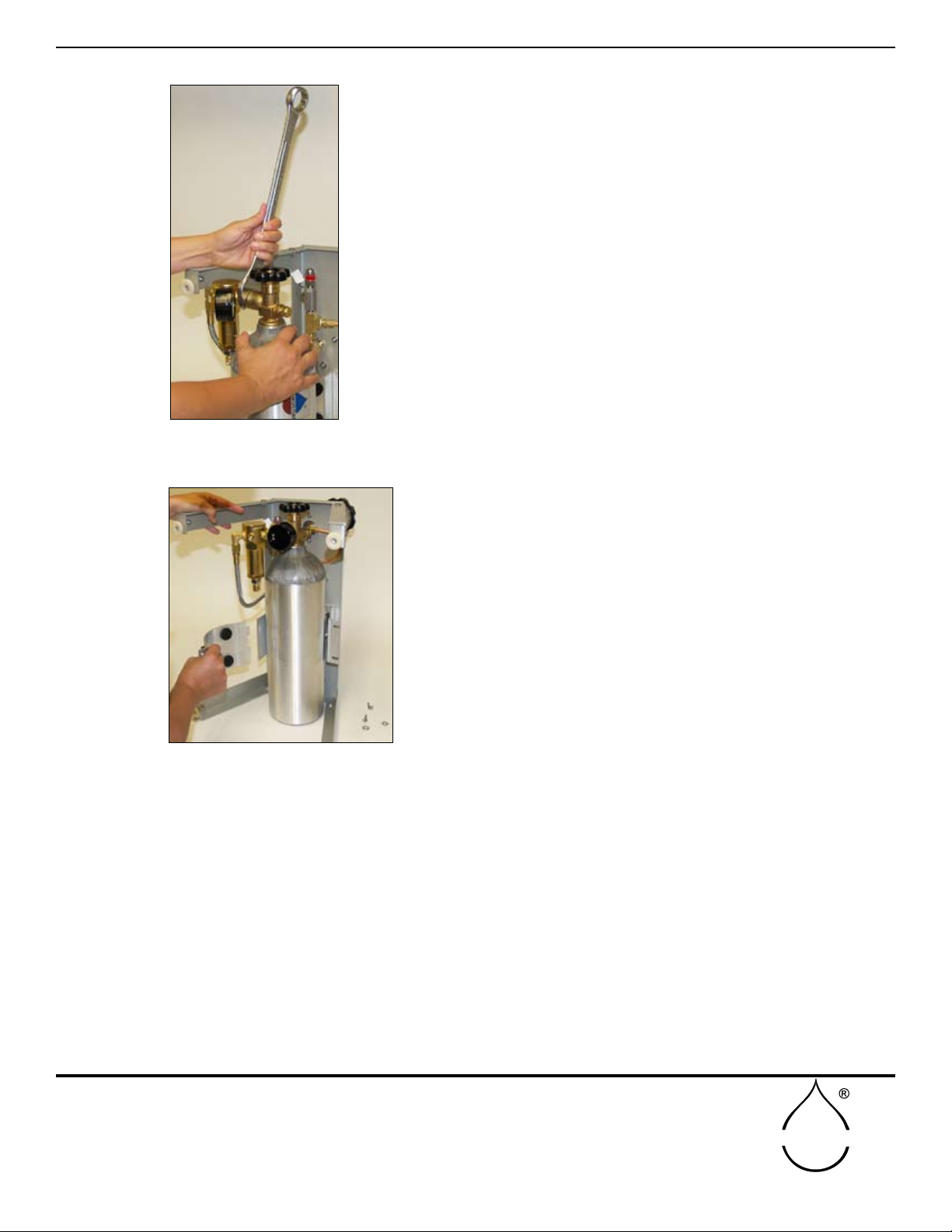
Step 2
Loosen and undo the 1-1/8 inch lock nut that holds the tank. A
1-1/8 inch open-end wrench or a crescent wrench of sufcient size
is required for this operation (Fig. 16). This lock nut has a right-
hand thread and therefore the nut must be turned in a counter-
clockwise direction to undo it.
When the lock nut is completely removed from the storage tank t-
ting, the pressure regulator will separate from the gas cylinder and
can be left hanging from its stainless steel connecting tube.
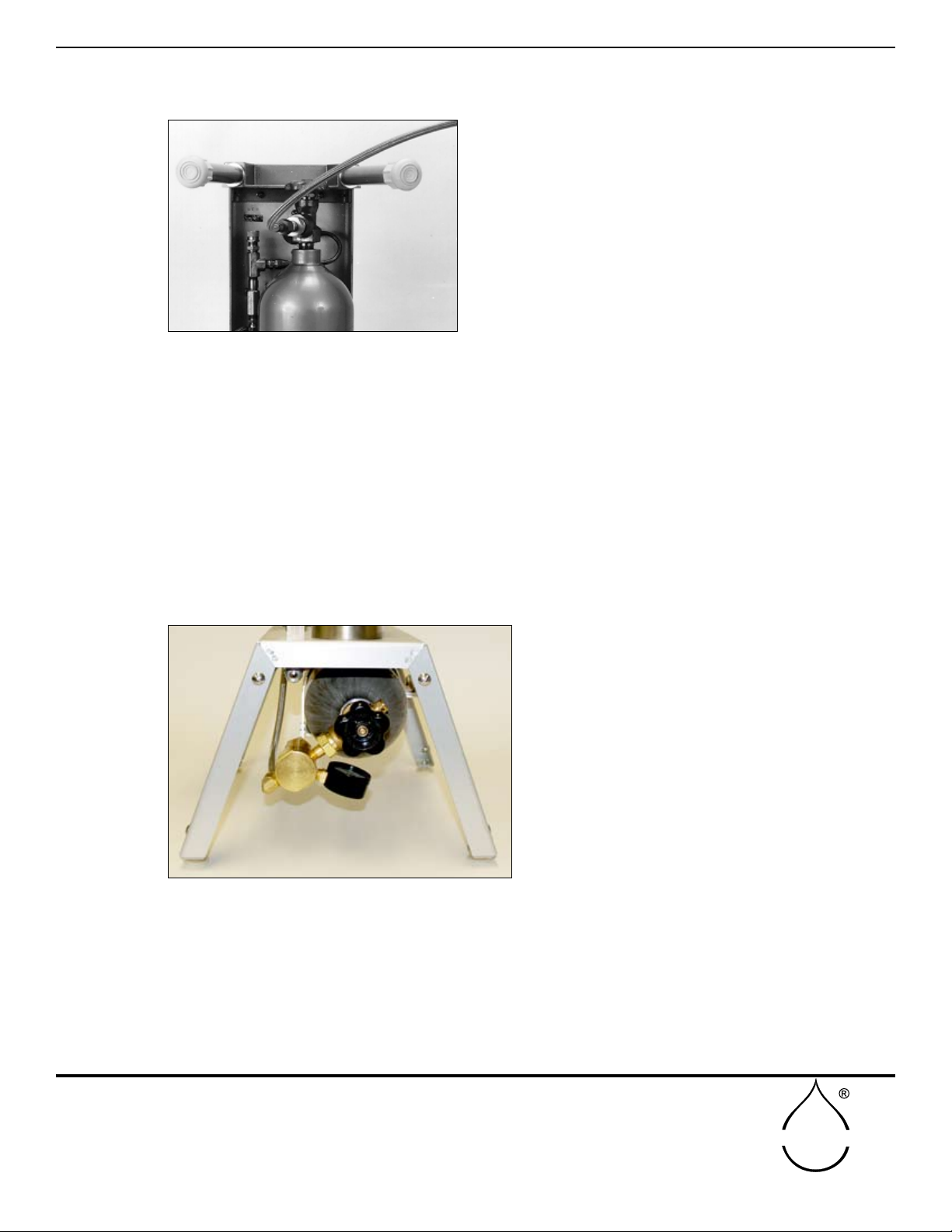
If the storage tank needs to be removed completely, loosen the
bottle bracket wing nut, then swing the closure bolt free from the
hinged bracket (Fig. 17).
The compressed gas cylinder can be relled with gas while it is
still mounted to the console after the regulator has been removed.
GENERAL CARE AND MAINTENANCE
Fig. 16 - Removing the tank by
loosening the bolt.
Fig. 17 - Disconnect the bracket
13
SOILMOISTURE EQUIPMENT CORP.
P.O. Box 30025, Santa Barbara, CA 93105 U.S.A.
Telephone 805-964-3525 - Fax No. 805-683-2189
sales@soilmoisture.com - www.soilmoisture.com
SOILMOISTURE
HOW TO REFILL THE COMPRESSED GAS CYLINDER
To ll the storage tank from a larger supply tank, our Model
0777L60 valved ller hose is used (Fig.18). The lock nuts
on the ends of the exible hose are tightened securely in
place on both tanks, using a 1-1/8” open-end wrench or
the equivalent. The tank valve on the small storage tank is
now opened rst.
The valve on the larger pressure supply tank is then
opened slowly so that the high pressure air from the large
tank can ow to the small tank. After a period of time, when
no further ow noise of gas is observed, the valve on the
large tank is sealed shut. The valve on the smaller tank is then closed securely. After the valves on both
tanks are closed, the lock nut on one end of the hose is loosened slowly. High pressure gas within the
exible hose will drain out of the loosened end. Thereafter, the exible high pressure hose is removed
from both tanks. After lling, the pressure regulator is again connected to the compressed gas cylin-
der. The round nose on the connection tting of the pressure regulator makes the pressure seal to the
compressed gas cylinder. The lock nut serves only to hold this round nose securely in contact with the
mating tting on the tank. The threads of the lock nuts themselves do not make a pressure seal.
Tighten the lock nut securely.
NOTE: If the compressed gas cylinder has
been removed from the console, be sure that
it is oriented in the proper position (Fig. 19), so
that the regulator ts correctly below the con-
sole.
The pressure gauge on the pressure regula-
tor should be in a "face up" position when the
storage tank is oriented properly.
Fig. 18 - Valve ller hose
Fig. 19 - Angle of the pressure regulator
GENERAL CARE AND MAINTENANCE (cont.)
14
SOILMOISTURE EQUIPMENT CORP.
P.O. Box 30025, Santa Barbara, CA 93105 U.S.A.
Telephone 805-964-3525 - Fax No. 805-683-2189
sales@soilmoisture.com - www.soilmoisture.com
SOILMOISTURE
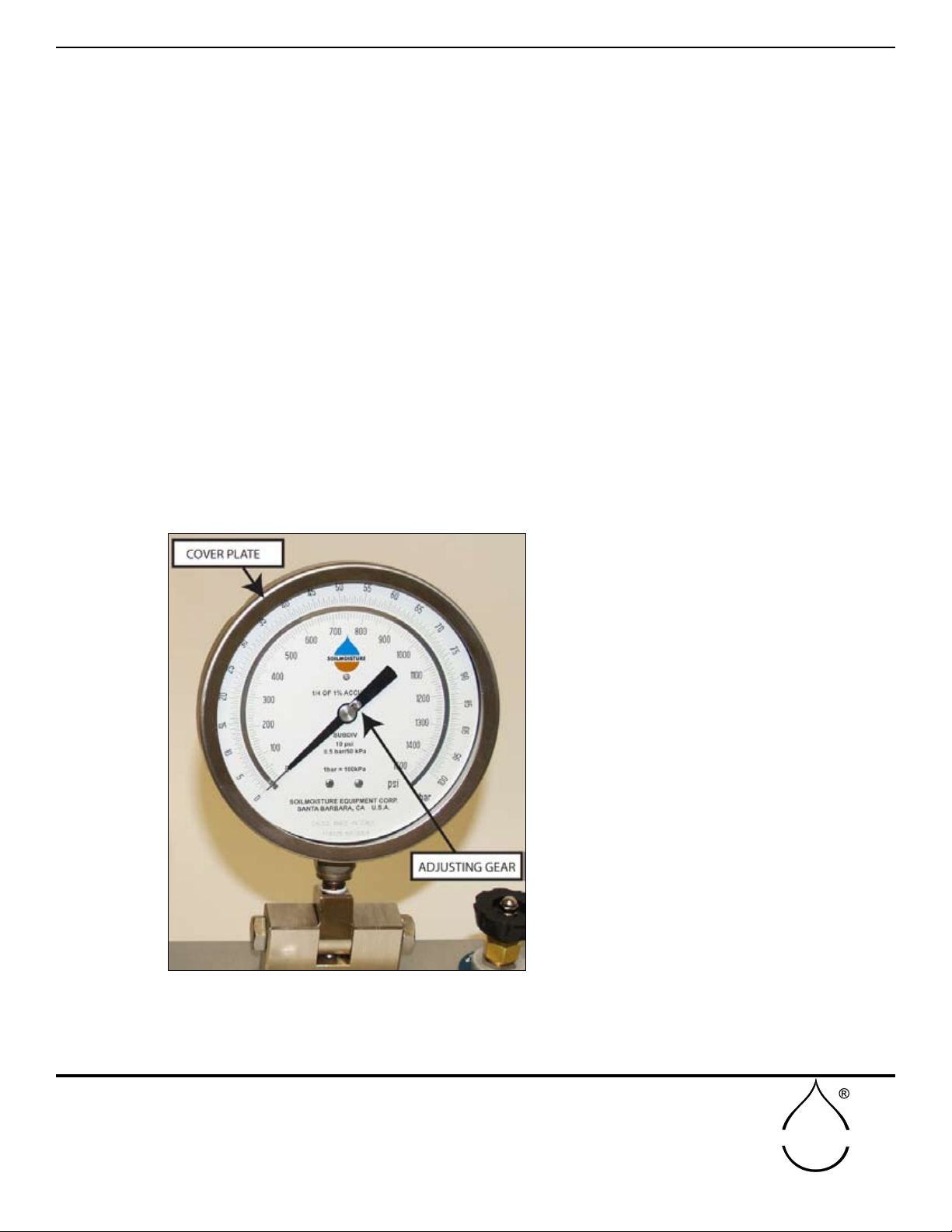
TO ADJUST THE ZERO POSITION OF THE PRESSURE READOUT GAUGE
In the event the pointer is jarred off of the zero position during transportation and handling, it can be
re-zeroed easily. To do this, unscrew the cover plate of the test gauge by turning it counterclockwise.
The zero adjusting gear (Fig. 20) on the gauge
pointer is then turned clockwise or counter-
clockwise with the adjusting tool supplied with
the unit to bring the pointer back to the zero po-
sition.
Replace the cover plate by screwing it on in a
clockwise position. Tighten securely to prevent
inltration of dust into the gauge.
Note: On special units the readout pressure
gauge is sometimes supplied with a friction-type
adjustable pointer. If this type of gauge is on
your unit, the zero position of the pointer is ad-
justed by grasping the knurled disc at the center
of the pointer and moving the pointer itself with
respect to this disc until the desired zero posi-
tion is obtained.
MINOR ADJUSTMENTS
Fig. 20 - Zero adjust
Keep the cam area and specimen holder "O" ring area and relief valve areas clean and free of •
dirt.
Do not block the bottom of the pressure vessel that could prevent air exhaust.•
Do not leave the pressure vessel pressurized while not in use.•
HELPFUL HINTS IN NORMAL USE
TROUBLESHOOTING
Leaking at the valve stem on the 3-way ball valve or metering valve
Remove handle and either remove stem nut to remove the stem assembly for cleaning, lubricating with
light oil and re-assembly or just tightening of the valve stem nut to stop the leaking. You may want to
just tighten the nut rst to see if that is all that is needed to stop the leak.
Locating leaks elsewhere when the unit is not holding pressure
Use soapy water and a small brush and check every joint in the system for leaks. Fix where possible.

15
SOILMOISTURE EQUIPMENT CORP.
P.O. Box 30025, Santa Barbara, CA 93105 U.S.A.
Telephone 805-964-3525 - Fax No. 805-683-2189
sales@soilmoisture.com - www.soilmoisture.com
SOILMOISTURE
Specimen Holders and Specified Grommets
SEALING
SLEEVES
STEM GROMMETS
(use with petioles)
LEAF GROMMETS
(use with leaves or grasses)
SUPPORT
WASHERS
3018G4BLKPKG05
1/2”OD,
BLANK
3018G4D062PKG05
1/2”OD,
1/16”DIAM. HOLE
3018G4D125PKG05
1/2”OD,
1/8”DIAM. HOLE
3018G4D187PKG05
1/2”OD,
3/16”DIAM. HOLE
3018G4D250PKG05
1/2”OD,
1/4”DIAM. HOLE
3019G4DBLKPK5
BLANK
3019G4D062PK5
1/16”DIAM. HOLE
3019G4D093PK5
3/32”DIAM. HOLE
3019G4D125PK5
1/8”DIAM. HOLE
3019G4D187PK5
3/16”DIAM. HOLE
3019G4D375PK5
3/8”DIAM. HOLE
3019G4D500PK5
1/2”DIAM. HOLE
3019G4UTE01PK5
1/16”WIDE x 1/4” ELIPSE
3019G4UTS01PK5
.050”WIDE x 1/2” SLOT
3019G4UTE02PK5
1/8”WIDE x 1/2” ELIPSE
3019G4UTA01PK5
1/8”WIDE x 1/2” ARC
3020G4BLKPK5
BLANK
3020G4D141PK5
9/64” DIAM. HOLE
3020G4D250PK5
1/4” DIAM. HOLE
3020G4D375PK5
3/8” DIAM. HOLE
3020G4D500PK5
1/2” DIAM. HOLE
3020G4UTE01PK5
1/16”WIDE x
1/2” SLOT
3020G4UTE02PK5
1/8”WIDE x
1/2” SLOT
3019G4D250PK5
1/4”DIAM. HOLE
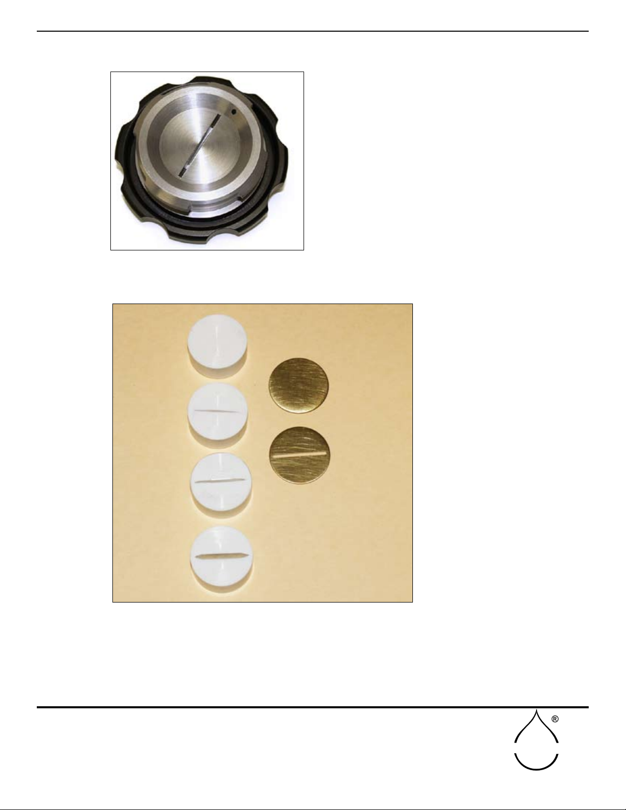
(Fig. 22) - Complete G4 Grommet kit (3019G4K3) shown above
The G4 Specimen Holder (Fig. 21) is a General Purpose Holder. It can be
set up to accept round petioles from 1/32 inch diameter to 1/2 inch diameter;
for short petioles from 1 cm long; and for blade-type leaves up to 1/2 inch
wide and on mid-vein of larger leaves. Above, (Fig. 22) are the range of
Grommets, Sealing Sleeves, and Support Washers used with the Plant Water Status Console using
the G4 Specimen Holder.
The rst stem Grommet, second column, (Fig. 22),a solid Grommet (no hole), can be used for testing
the system for leakage or to make your own Grommet. The next ve Grommets in the same column,
are used for testing petioles from the size of pine needles up to thick leaves, selection based on the size
of the petiole to be tested. The last item in the row, with the very large hole, is a Grommet that accepts
the sealing sleeves shown in the rst column (Fig. 22).
Rather than disassembling the specimen holder for each test, the sealing sleeves can be quickly taken
in and out of the Grommet for fast sampling.
The Grommets with slits in them, third column, (Fig. 22), are usually used for testing large leaves or
grass blades.
The G4 Series Brass Support Washers, fourth column, (Fig. 22), are used in conjunction with the
Grommets to protect the Grommet when the knob is tightened, thereby providing equal pressure over
the entire surface of the Grommet. The Support Washers also prevent the Grommet from being pushed
out of the specimen holder when pressurized.
(Fig.21) Model 3015G4
Specimen Holder
16
SOILMOISTURE EQUIPMENT CORP.
P.O. Box 30025, Santa Barbara, CA 93105 U.S.A.
Telephone 805-964-3525 - Fax No. 805-683-2189
sales@soilmoisture.com - www.soilmoisture.com
SOILMOISTURE
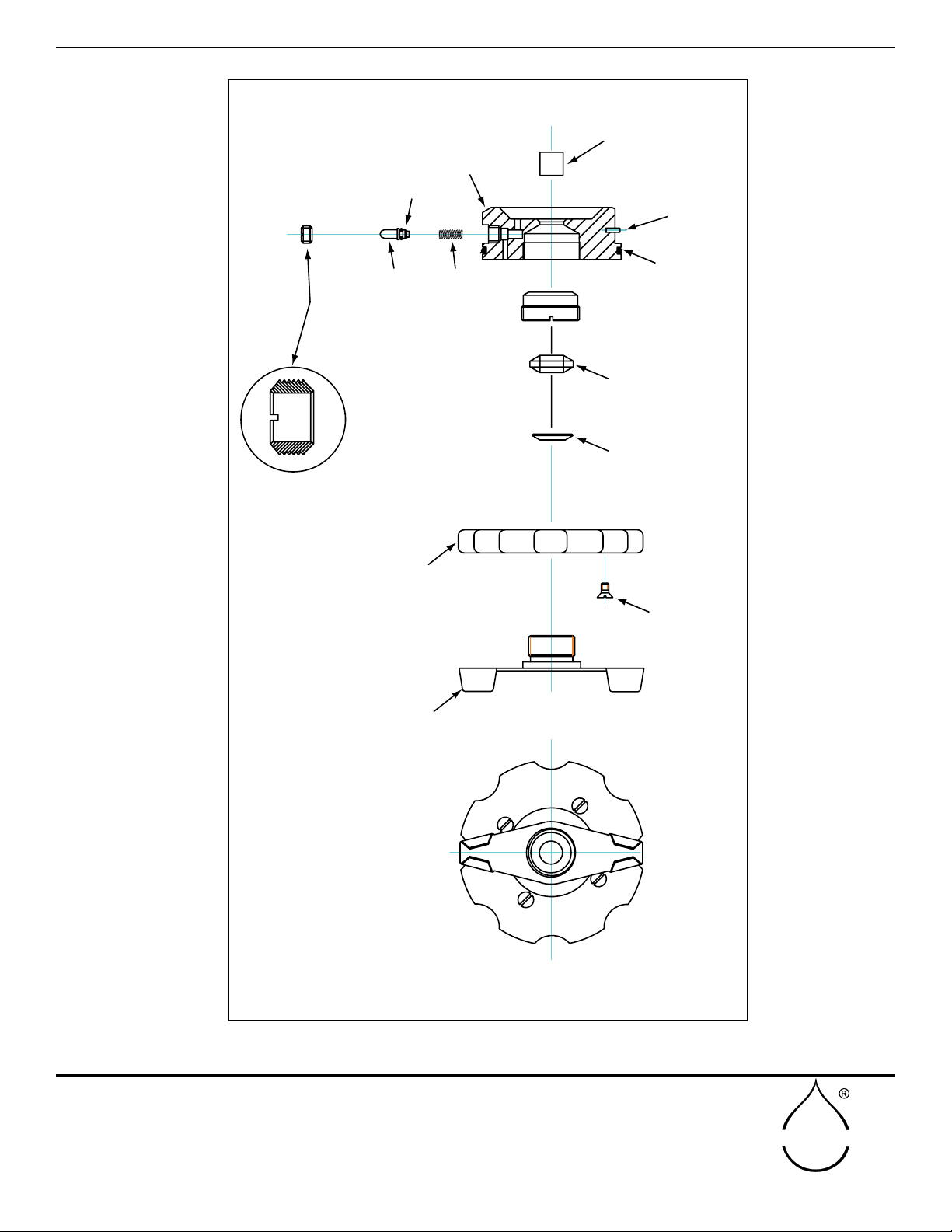
3015G4-100
M802X003
M802X149PKG04
MSL014-005
MSM002-002
Q0832CAQ05
3015G1-004
3015G4-001
3015G4-003
3015G4-002
SEALING KNOB
O-RING
PIN 3/32 DIA x 5/16
SCREW, FLT HD 8-32 x 5/16
SPRING
O-RING
SUPPORT WASHER
SEALING SLEEVE
GROMMET
HOUSING
CLOSING RING
INSERT
PISTON
DESIGNED TO ACCEPT ROUND PETIOLES FROM 1/32”DIA. TO 1/2” DIA.
Model 3015G4 Specimen Holder Assembly
Z3015G1-005
RETAINING COLLAR
(LARGER VIEW)
Fig. 23 - Replacement parts for Model 3015G4
Specimen Holder Assembly
G4 Specimen Holder REPLACEMENT PARTS
17
SOILMOISTURE EQUIPMENT CORP.
P.O. Box 30025, Santa Barbara, CA 93105 U.S.A.
Telephone 805-964-3525 - Fax No. 805-683-2189
sales@soilmoisture.com - www.soilmoisture.com
SOILMOISTURE
3017G2WBLKPKG05
BLANK
3017G2WRZRPKG05
RAZOR CUT
3017G2W090PKG05
SLOT 1.5” X .094
3017G2W050PKG05
SLOT 1.15” X .050
3021G2-000K1
BLANK
3021G2-001K1
1/16” SLOT
GROMMETS
SUPPORT
WASHERS
The G2 Specimen Holder (Fig. 25) is used specically for blade-type leaves up to 1 inch in width.
The items shown in the left column of (Fig. 24), are called Grommets. They are for use with broad
leaves or grasses; and the brass items shown, in the right column, are called Support Washers.
NOTE: The 3017G2 Series Grommets can only be used with the G2 Specimen Holder.
(Fig.24) MODEL 3017G2K1
G2 Series Complete Grommet Kit
G2 Specimen Holder (used for Blade-type Leaves)
(Fig.25) Model 3015G2
Specimen Holder
18
SOILMOISTURE EQUIPMENT CORP.
P.O. Box 30025, Santa Barbara, CA 93105 U.S.A.
Telephone 805-964-3525 - Fax No. 805-683-2189
sales@soilmoisture.com - www.soilmoisture.com
SOILMOISTURE
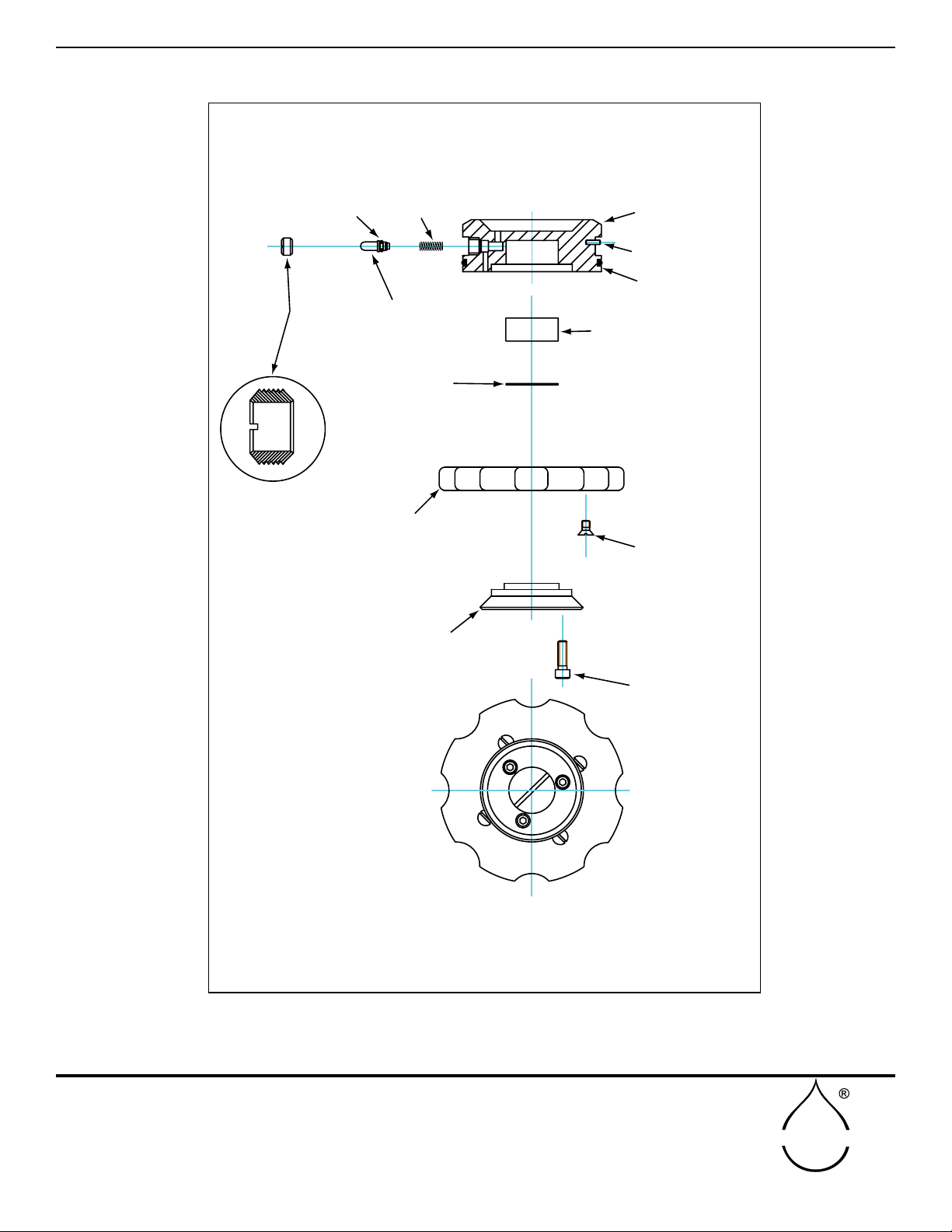
3015G4-003
MSM002-002
Q1024CAF10
Q0832CAQ05
M802X003PKG05
M802X149PKG04
MSL014-005
3015G1-004
Z3015G1-005
3015G2-002
3015G2-001
CLOSING RING
SCREW, FLT. HD. 8-32 X 5/16
SCREW, SOC.HD.CAP
10-24 X 5/8
SPRING
SEALING SLEEVE
SUPPORT WASHER
0-RING
O-RING
ROLL PIN
COMPRESSION RING
RETAINING COLLAR PISTON
HOUSING
DESIGNED TO ACCEPT BLADE-TYPE LEAVES UP TO 1” IN WIDTH.
Model 3015G2 Specimen Holder Assembly
(LARGER VIEW)
Fig. 26 - Replacement parts for Model 3015G2
Specimen Holder Assembly
G2 Specimen Holder REPLACEMENT PARTS

19
SOILMOISTURE EQUIPMENT CORP.
P.O. Box 30025, Santa Barbara, CA 93105 U.S.A.
Telephone 805-964-3525 - Fax No. 805-683-2189
sales@soilmoisture.com - www.soilmoisture.com
SOILMOISTURE
NOTES

20
SOILMOISTURE EQUIPMENT CORP.
P.O. Box 30025, Santa Barbara, CA 93105 U.S.A.
Telephone 805-964-3525 - Fax No. 805-683-2189
sales@soilmoisture.com - www.soilmoisture.com
SOILMOISTURE
NOTES
This manual suits for next models
1
Table of contents
Other Soilmoisture Equipment Laboratory Equipment manuals


Popular Laboratory Equipment manuals by other brands

V&P Scientific
V&P Scientific VP 710U5 Operation manual

Swegon
Swegon REACT Va Instructions for use

Sartorius
Sartorius Vivaspin 500 operating instructions

PreOmics
PreOmics BeatBox user manual

Nickel-Electro
Nickel-Electro NE4-T Series manual

Thermo Electron
Thermo Electron 3911 Operating and maintenance manual


Welch Allyn
Welch Allyn RetinaVue 100 Imager Directions for use

Binder
Binder C 170 operating manual

Hettich
Hettich MIKRO 200 operating instructions

Cole Parmer
Cole Parmer Geno/Grinder HG-600 quick start guide

VERDER
VERDER Carbolite Gero HTMA 7/220 Installation, operation and maintenance instructions

Drawell
Drawell Gentier 96E user manual