Soilmoisture Equipment PR16 User manual
September 2023
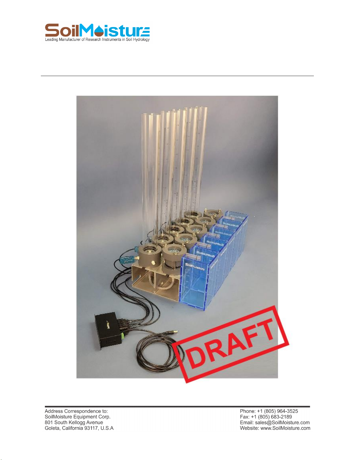
PR16
QUICK START GUIDE
The Next Generation of the Chameleon Laboratory Permeameter

2
P.O. Box 30025, Santa Barbara, CA 93130 U.S.A. | Phone: (805) 964-3525 | Fax: (805) 683-2189
Email: sales@soilmoisture.com | Website: http://www.soilmoisture.com
UNPACKING
Your PR16 Lab Permeameter has been thoroughly tested before shipment. When packed, it was in
perfect working order. Unpack with care, being sure to remove all packing material. Follow the
instructions carefully in order to ensure long, trouble-free service. Any damage found upon receipt
should be reported immediately to the transport carrier for claim. It is important to save the shipping
container and all evidence to support your claim. Be sure to read all operating instructions thoroughly
before operating the unit.
WARRANTY & LIABILITY
Soilmoisture Equipment Corp. (SEC) warrants all products manufactured by SEC to be free from defects
in materials and workmanship under normal use and service for twelve (12) months from the date of
invoice provided the section below has been met. Soilmoisture Equipment Corp. (SEC) is not liable for
any damage, actual or inferred, caused by misuse or improper handling of its products. SEC products are
designed to be used solely as described in these product operating instructions by a prudent individual
under normal operating conditions in applications intended for use by this product.

3
P.O. Box 30025, Santa Barbara, CA 93130 U.S.A. | Phone: (805) 964-3525 | Fax: (805) 683-2189
Email: sales@soilmoisture.com | Website: http://www.soilmoisture.com
Features
The PR16 Lab Permeameter is an accurate and fully automated laboratory system for measuring soil
core saturated hydraulic conductivity (Ksat). The PR16 is capable of performing Ksat measurement
according to Falling-Head Method and also Constant-Head Method procedures. Thanks to the Monitor®
Precision Pressure Transducer, and the Chameleon Software Application, both measurement methods
are fully automated. The PR16 comes with all required components (computer is NOT included in the
standard kits).
Applications:
Laboratory hydraulic conductivity measurement is a very common measurement method used in
educational applications, agricultural research, irrigation projects, construction projects, mining sites
studies, oil industry, environmental studies, geological studies and more.
Specifications
Standard Reservoir:
Reservoir Inside Diameter: 5.13 cm
Reservoir Increments: 5 cm to 45 cm, 1 mm resolution.
Reservoir Cross-Sectional Area: 20.67 cm2
Reservoir Volume: 930 mL
50 mm ID Sample Ring (Model PR16 and Model PR16-5)
Sample Ring Inside Diameter: 5.0 cm
Sample Ring Height: 5.0 cm
Sample Ring Inside Cross-Sectional Area: 19.6 cm2
Sample Ring Volume: 98.2 mL
80 mm ID Sample Ring (Model PR16-81, PR16-85)
Sample Ring Inside Diameter: 8 cm
Sample Ring Height: 5.0 cm
Sample Ring Cross-Sectional Area: 50.3 cm2
Sample Ring Volume: 251.3 mL
Pressure Transducer: Monitor™Precision Transducer (-100 kPa to +100 kPa). Please refer to the product
manual for more details.
System Resolution: 0.1 cmH2O (0.01 kPa)
Software Application: Please refer to Monitor Transducer Software Application manual.
NOTE: The Chameleon Software Application (for PC) can control up to independent 20 independent
units simultaneously.

4
P.O. Box 30025, Santa Barbara, CA 93130 U.S.A. | Phone: (805) 964-3525 | Fax: (805) 683-2189
Email: sales@soilmoisture.com | Website: http://www.soilmoisture.com
System Options
Model PR16: Single Unit, Flow Cell: 5.0 cm ID, 5.0 cm Length
Model PR16-5: Five Independent Units, Flow Cell: 5.0 cm OD, 5.0 cm Length
Model PR16-81: Single Unit, Flow Cell: 8.0 cm ID, 5.0 cm Length
Model PR16-85: Five Independent Units, Flow Cell: 8.0 cm ID, 5.0 cm Length
Acquaint Yourself with the PR16 Components
Major Components of the PR16 Setup.
5
P.O. Box 30025, Santa Barbara, CA 93130 U.S.A. | Phone: (805) 964-3525 | Fax: (805) 683-2189
Email: sales@soilmoisture.com | Website: http://www.soilmoisture.com
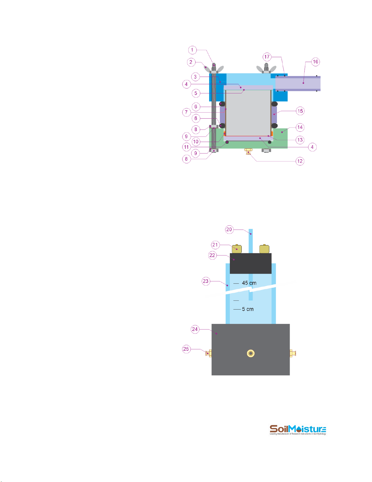
PR16 Flow Cell
1. Flow Cell Stud
2. Stud Wingnut
3. Flow Cell Cap
4. Perforated Plate
5. Mesh Screen
6. Cylinder O-ring
7. Sample Ring
8. Stud Nut
9. Stud Washer
10. Paper Filter Retainer
11. Flow Cell Base O-ring
12. Flow Cell Base Port
13. Paper Filter
14. Flow Cell Base
15. Spacer Cylinder
16. Drainage Pipe
17. Drainage Pipe O-ring
PR16 Reservoir
20. Air Tube
21. Top Port
22. Stopper
23. Body Pipe
24. Base
25. Side Port
6
P.O. Box 30025, Santa Barbara, CA 93130 U.S.A. | Phone: (805) 964-3525 | Fax: (805) 683-2189
Email: sales@soilmoisture.com | Website: http://www.soilmoisture.com
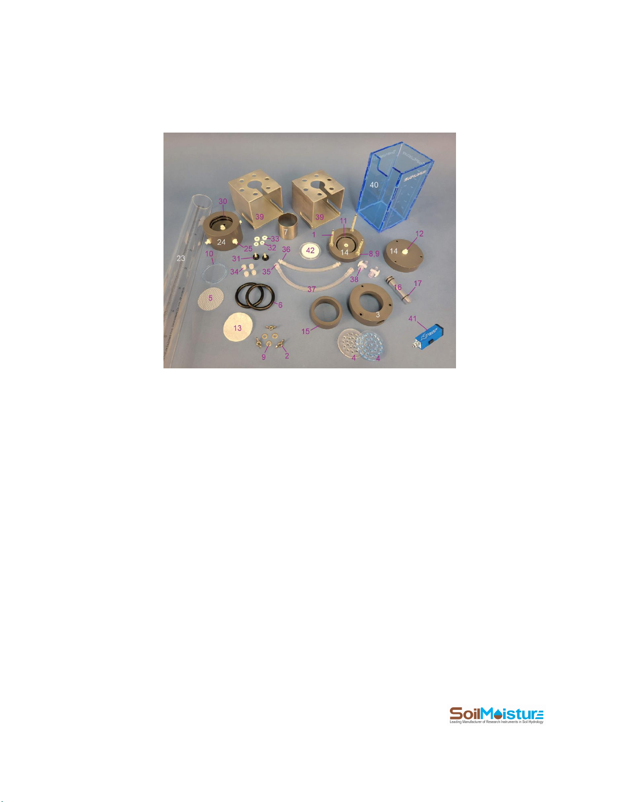
PR16 Parts
30. Reservoir O-ring
31. Stand Knob
32. Knob Centralizer
33. Knob Spacer
34. Port Plug
35. Male Luer hose Connection
36. Female Luer Hose Connection
37. Tubing
38. Stopcock
39. Stand
40. Receiver
41. Monitor™Precision Pressure Transducer
42. Extraction Plate (not included, not needed for Ksat
measurement)
7
P.O. Box 30025, Santa Barbara, CA 93130 U.S.A. | Phone: (805) 964-3525 | Fax: (805) 683-2189
Email: sales@soilmoisture.com | Website: http://www.soilmoisture.com
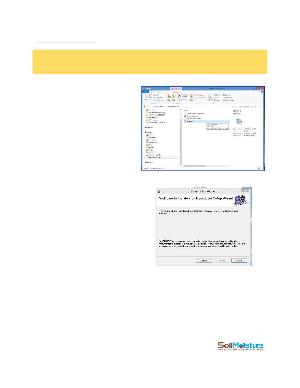
Software Installation
NOTE: The latest version of the Chameleon Software Application can always be downloaded for free from the
SoilMoisture webpage below.
https://www.soilmoisture.com/resources/Software-Downloads/
+ Open the Windows Explorer, go to the USB drive
and run “setup.exe” file.
+ Click “Next” in the “Monitor Transducer”
window.
8
P.O. Box 30025, Santa Barbara, CA 93130 U.S.A. | Phone: (805) 964-3525 | Fax: (805) 683-2189
Email: sales@soilmoisture.com | Website: http://www.soilmoisture.com
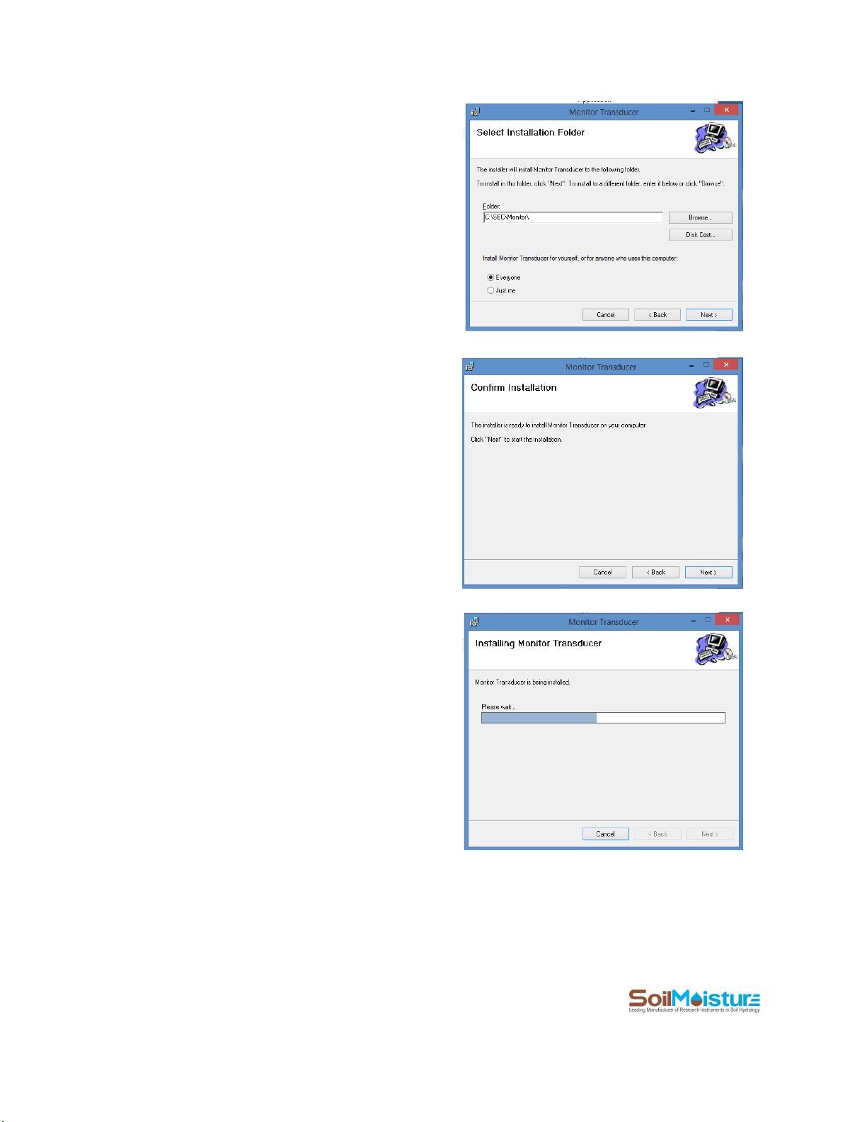
+ Click the “Browse” Button in the “Select Installation
Folder” window to select the installation folder.
We recommend the default folder
“C:\SEC\Monitor\”. Click the “Disk Space” to see a list
of your drives and space available on each of them.
Select “Everyone” if you would like other people to
access to the program. Otherwise select the “Just
me” option.
Click “Next” when you are done.
+ Select “Next” in the “Confirm Installation” window if
you would like the software to get installed on your
computer.
+ The following window pops up. Please wait. The
installation process should not take longer than a
couple of minutes.
9
P.O. Box 30025, Santa Barbara, CA 93130 U.S.A. | Phone: (805) 964-3525 | Fax: (805) 683-2189
Email: sales@soilmoisture.com | Website: http://www.soilmoisture.com
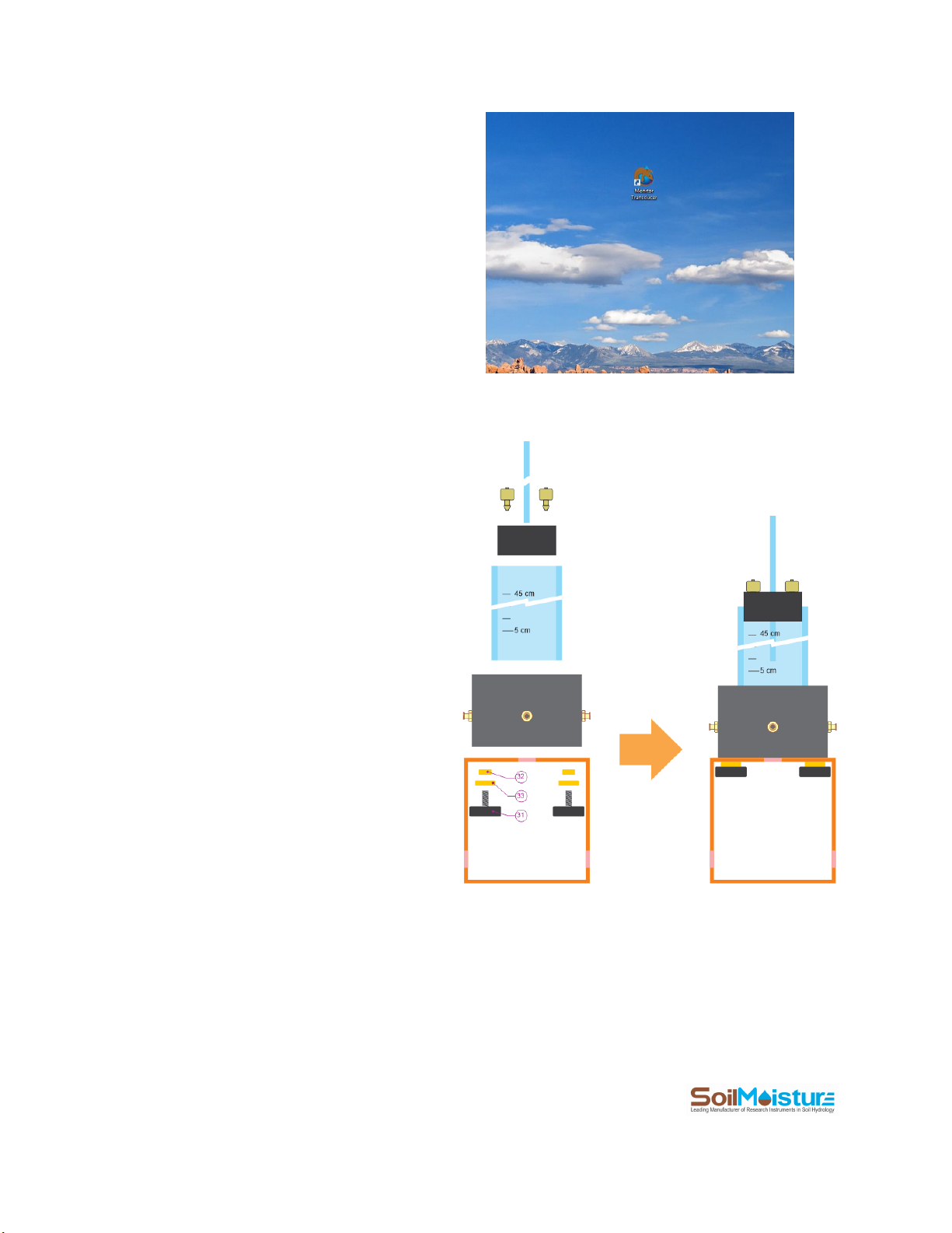
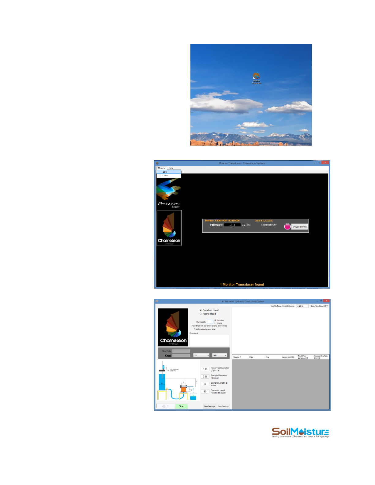
+ Click “Close” in the “Installation Complete” window.
A Windows Shortcut (Monitor Transducer) will be
created on your computer Desktop.
Assemble the Reservoir
Assemble the Reservoir according to the
schematic.
Use a small amount of Vacuum Grease to lubricate
the Air Tube and insert it in the central hole of the
Stopper.
Scure the Base to Stand using Stand Knobs and
items 31 and 32.
Before attaching the Body Pipe to the Base make
sure that the Reservoir O-rings are in place.
Lubricate the O-rings with Vacuum Grease if
needed.
Scure the Stopper to the top of the Pipe and make
sure that it is sealed to the Pipe (airtight).
10
P.O. Box 30025, Santa Barbara, CA 93130 U.S.A. | Phone: (805) 964-3525 | Fax: (805) 683-2189
Email: sales@soilmoisture.com | Website: http://www.soilmoisture.com
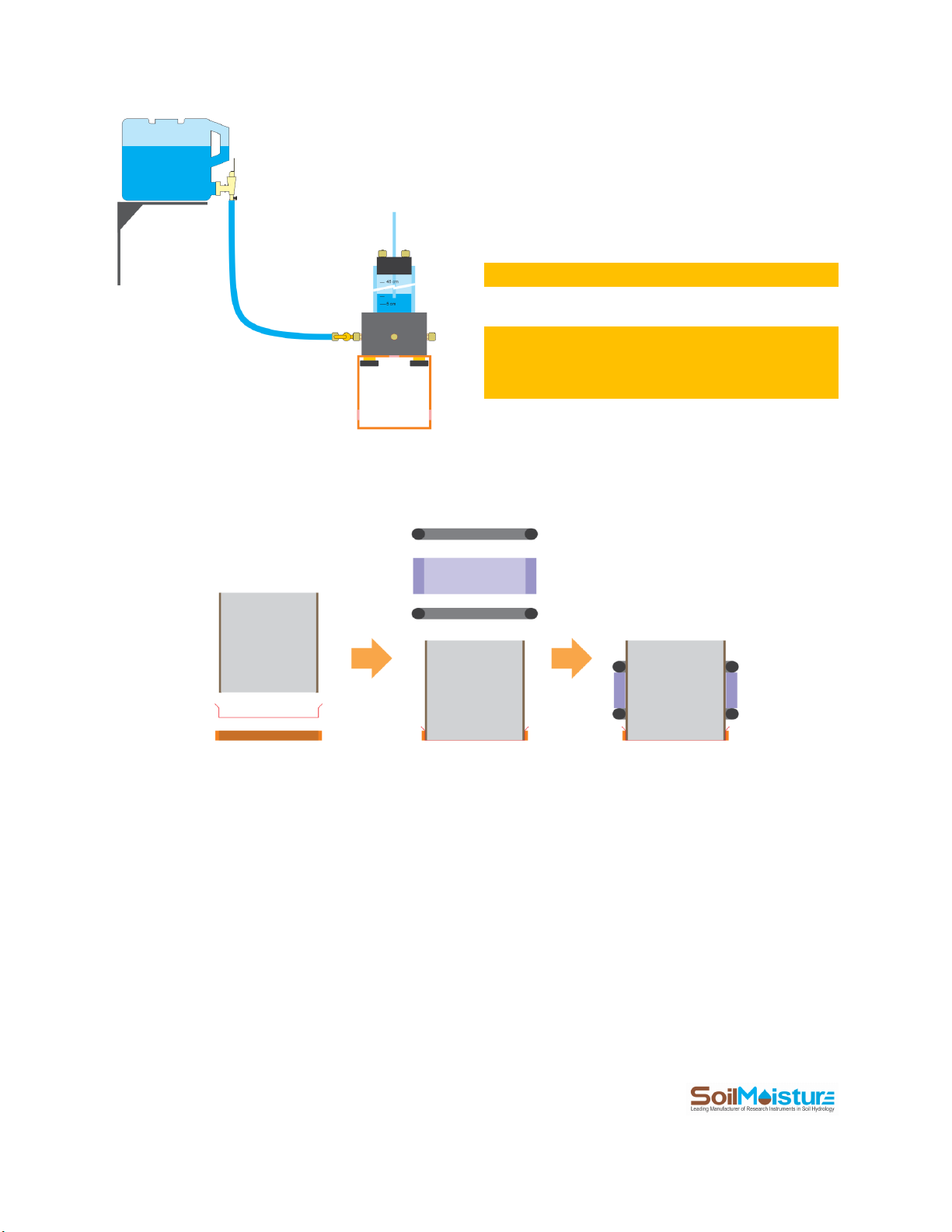
The Reservoir has 4 side ports. One of them can be
used for refilling the Reservoir. This eliminates the
need to remove the Stopper for refilling.
You can connect the Reservoir to tap water, or to
an elevated water reservoir (see the schematic).
NOTE: the “elevated reservoir”is NOT included.
NOTE: in case you connect the Reservoir to a
water tap, close the water faucet after each
refilling.
Assemble the Sample Ring
Place the Paper Filter Retainer over an even surface like tabletop. Then place a Paper Filter over it. Try to center
the Filter with the Retainer. Now, carefully place the Sample Ring over the Paper Filter and gently push it into the
Paper Filter Retainer. If the Paper Filter torn, try again with a new Filter
Insert the Cylinder O-rings and Spacer Cylinder around the Sample Ring (see the schematic above).
11
P.O. Box 30025, Santa Barbara, CA 93130 U.S.A. | Phone: (805) 964-3525 | Fax: (805) 683-2189
Email: sales@soilmoisture.com | Website: http://www.soilmoisture.com
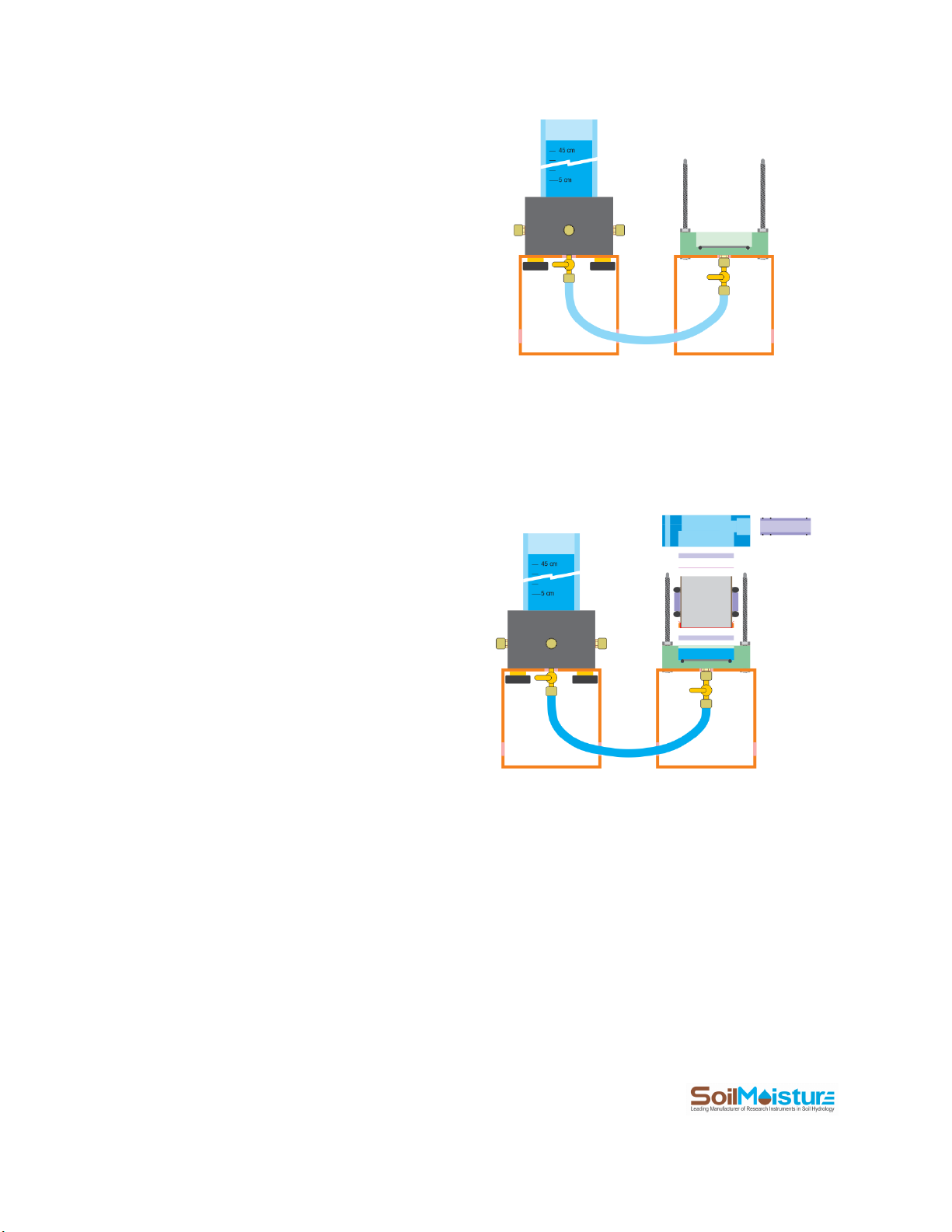
Saturate the Soil Sample
Connect a Stopcock to the Flow Cell Base and
another Stopcock to the Reservoir Base.
Then connect the Reservoir to the Flow Cell Base
using the Tubing provided.
Considering the vertical and horizontal distance of
the Reservoir and the Flow Cell, cut the tubing to
a length that is convenient and not too long. A
length of 15 to 20 cm is recommended.
Open the Stopcocks and let water flow freely and
fill up a bout ¾ of the Flow Cell Base.
You also need to get rid of all bubbles in the water
path between the Reservoir and the Flow Cell
Base. You’ll be able to do this effectively with a
little practice. Note that very small bubbles that
do not limit the flow rate significantly do not
create any issues.
Make sure that the Flow Cell O-ring is in place.
Submerge one of the Perforated Plates in the
water collected inside the Flow Cell Base.
Make sure that all three Drainage Pipe O-rings are
in place. Connect the Drainage Pipe to the Cap.
Carefully place the Sample Ring (containing soil)
on top of the Perforated Plate. Try not to trap air
bubbles under the Sample Ring.
Once the Sample Ring sits in place, carefully place
the Mesh Screen on top of it. Now, place the
second Perforated Plate over the Mesh Screen.
Align the Felow Cell Cap with the three Studs and
gently push it down. Centralize the Perforated
Plate and the Mesh Screen to go into the Cap. The
12
P.O. Box 30025, Santa Barbara, CA 93130 U.S.A. | Phone: (805) 964-3525 | Fax: (805) 683-2189
Email: sales@soilmoisture.com | Website: http://www.soilmoisture.com
bottom of the Cap should easily touch the
Cylinder O-ring.
Once the Cap is in place, put the Wingnuts over
the Studs and secure them “half turn at a time”.
This method is like securing the spare tire of a car.
It ensures even progress among the Wingnuts.
Please note that there is no need for
overtightening the Wingnuts. Do NOT use any
tools or leverage for tightening the Wingnuts!
Secure the Stopper to the top of the Reservoir.
Adjust the Air Tube at the 5 cm mark. This creates
a small overhead pressure. Connect Stopcocks to
the Stopper ports and close the Stopcocks.
Now open the Stopcocks connected to the Tubing. Water starts flowing from the Reservoir to the Flow Cell due to
the head height difference. The Air Tube should also start bubbling, which indicates water consumption from the
Reservoir.
Place the Receiver next to the Flow Cell to collect the drainage water.
Wait until the soil is completely saturated. Depending on the soil type, and the length of the sample, this might
take from several minutes to several days. Most ‘regular’soils need a day to get saturated.
Detecting free water on top of the soil sample and in the Drainage Pipe are signs that the soil is saturated.

13
P.O. Box 30025, Santa Barbara, CA 93130 U.S.A. | Phone: (805) 964-3525 | Fax: (805) 683-2189
Email: sales@soilmoisture.com | Website: http://www.soilmoisture.com
Measurement Campaign:
Constant Head Method
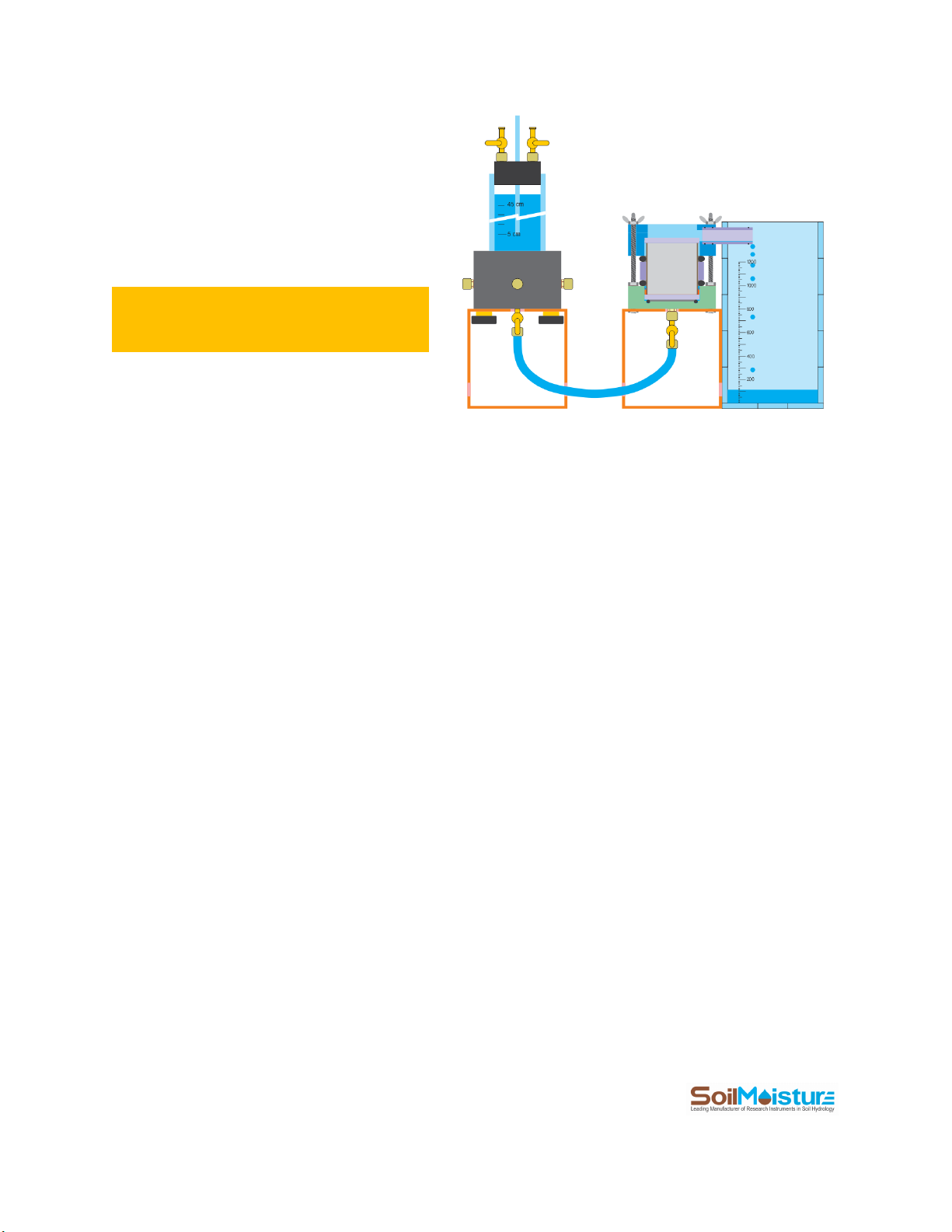
Constant-Head Setup
+ Set up the system according to the schematic attached.
+ Connect the Monitor Transducer to your computer using the USB cable provided with the system.
+ Open the Monitor Transducer program.
+ Make sure that Valve B is open (schematic above). This is to expose the pressure sensor to ambient air.
14
P.O. Box 30025, Santa Barbara, CA 93130 U.S.A. | Phone: (805) 964-3525 | Fax: (805) 683-2189
Email: sales@soilmoisture.com | Website: http://www.soilmoisture.com
+ Open the Monitor Transducer from your Desktop.
+ If the Monitor sensor reads a pressure
other than zero, go to “Monitor” menu
then click “Zero”. The pressure reading
should go to zero.
+ Once the sensor is zeroed, click on the
“Measurement” button to go to the “Lab
Saturated Hydraulic Conductivity
System” window. Here you can perform
your measurement campaign.
+ Select the “Constant Head” method.
+ In the “Log File Name” field, enter your
log file name. This is the file that will
contain your reading information. Try to
come up with descriptive names for your
reading files.
15
P.O. Box 30025, Santa Barbara, CA 93130 U.S.A. | Phone: (805) 964-3525 | Fax: (805) 683-2189
Email: sales@soilmoisture.com | Website: http://www.soilmoisture.com
+ In the “Reservoir Diameter” field enter Reservoir inside diameter (D). The PR16 Reservoir has an inside diameter
of 5.13 cm. Please also note that the outside diameter of Air Tube is assumed to be 0.635 cm (you are not able to
change it).
+ In the “Sample Diameter” field enter Sample Ring inside diameter (d). The inside diameter of PR16 ring is 5.0 cm.
+ In the “Sample Length” field enter sample length (Ls). The length of the PR16’s sample ring is 5.0 cm.
+ Adjust the head height (H). The Constant Head schematic contains some useful dimensions.
+ Select a unit for measured Saturated Hydraulic Conductivity (Ksat) using dropdown menus in front of Ksat.
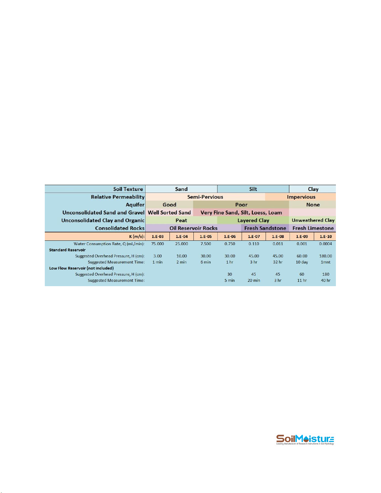
+ In the “Run test for” field, enter the duration of your measurement. As a rule of thumb, finer soils (more clay
content) need longer measurement time. While coarser soils (more sand content) need shorter measurement
time. The table below provides suggested head height and measurement time for each type of soil.
Suggested measurement parameters for standard Constant-head PR16 setup. Look up the suggested head height (H) and measurement time (T)
based on measured Water Consumption Rate (Q). Note that the table is created based on Sample Diameter (D) of 5 cm and Sample Length (L)
of 5 cm. Suggested Measurement Time is for making at least 5 consecutive readings.
16
P.O. Box 30025, Santa Barbara, CA 93130 U.S.A. | Phone: (805) 964-3525 | Fax: (805) 683-2189
Email: sales@soilmoisture.com | Website: http://www.soilmoisture.com
+ Make sure that the system is set up correctly. Valves A, B, C and D should be closed.
+ Open Valve D.
+ Open Valve A.
+ Wait until the Air Tube starts bubbling.
+ Wait for 5 more seconds for the system to stabilize.
+ Click the “Start” button to start a measurement.
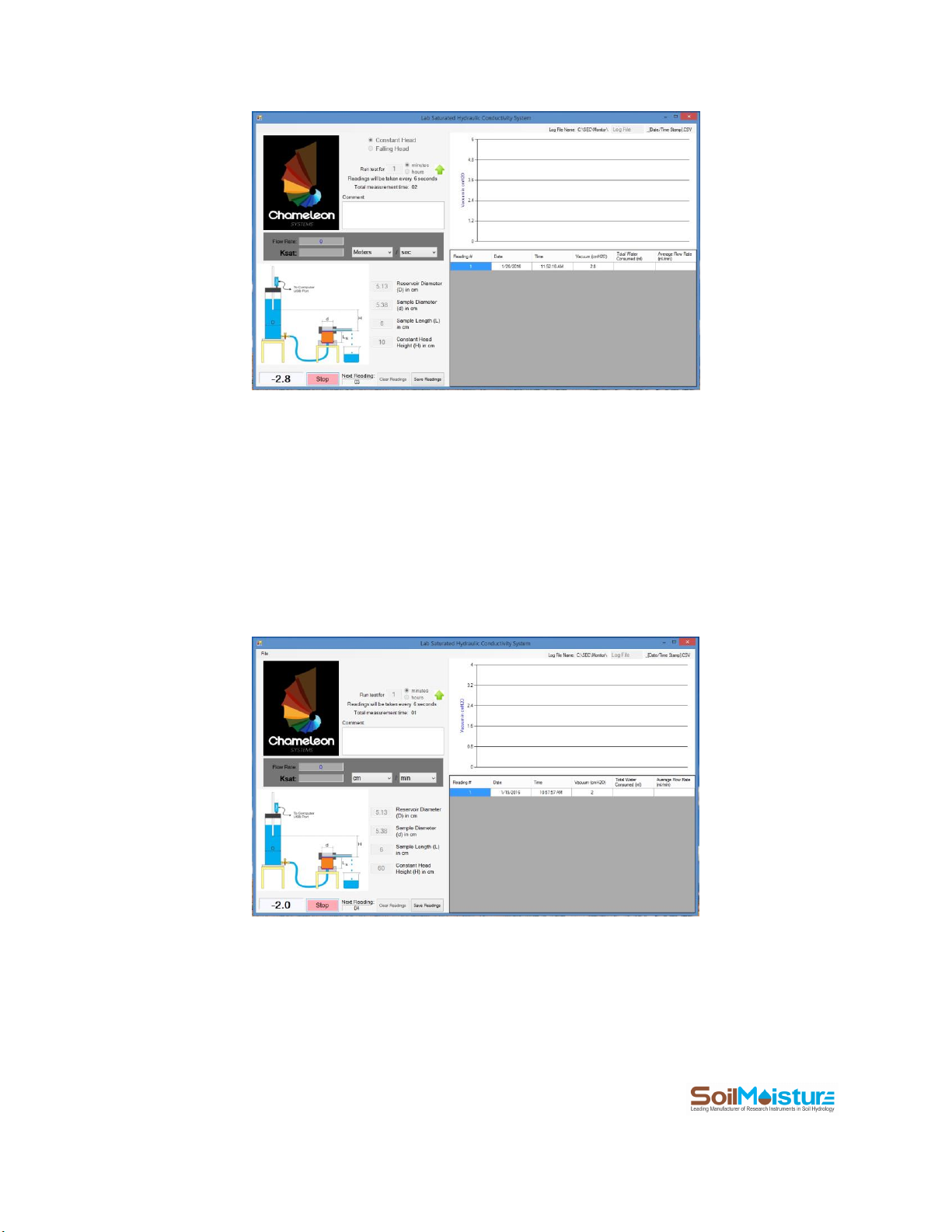
+ The first reading is made immediately. The software then divides the reading period into 10 equal increments
and makes a reading at the end of each time increment. If the increments are too short, the readings graph is
going to have a “step-like” trend (picture below). In that case you may want to increase the measurement time.

17
P.O. Box 30025, Santa Barbara, CA 93130 U.S.A. | Phone: (805) 964-3525 | Fax: (805) 683-2189
Email: sales@soilmoisture.com | Website: http://www.soilmoisture.com
A step-like reading graph is an indication of a too short measurement time.
+ Once you get the first Average Flow Rate values, compare them with the measurement parameters table. If you
need to readjust the head height or the measurement duration, do so and restart the measurement.
For example, looking at the reading graph in image above (one-minute measurement time), you are still able to see
some “step-like” effect. In other words, some readings have similar reading values. A Step-like graph suggests that
perhaps longer measurement duration gives you a more representative graph. Please note that a step-like graph
does not mean that the measurement is wrong. We increased the measurement duration to 2 minutes for the
same sample and restarted the measurement campaign. See how readings trend improved (image below).

18
P.O. Box 30025, Santa Barbara, CA 93130 U.S.A. | Phone: (805) 964-3525 | Fax: (805) 683-2189
Email: sales@soilmoisture.com | Website: http://www.soilmoisture.com
+ The Ksat value appears on the screen once the reading time is over (see the example screenshot above).
NOTE: The first reading and the last reading (green highlight in the Readings Table) are used for measuring the
Average Flow Rate and then Ksat.
The software keeps reading until you press “Stop”. This is a handy feature when you decide to keep going with the
measurement even after the designated measurement time is over. In case you need to increase the initial
measurement time to a longer interval, use the green up arrow right beside measurement duration field.
+ Click “Stop” whenever you would like to stop the reading process. The software gives you an option to use the
very last reading as the end point of your measurement. Click “Yes” if you would like to do so.
+ Click “Save”to save the readings and the results in a CSV file. The file address can be found at the top right
corner of the measurement window. You can open the reading file in MS-Excel or other similar programs. Below is
an example data file generated by the Chameleon software application.

19
P.O. Box 30025, Santa Barbara, CA 93130 U.S.A. | Phone: (805) 964-3525 | Fax: (805) 683-2189
Email: sales@soilmoisture.com | Website: http://www.soilmoisture.com

20
P.O. Box 30025, Santa Barbara, CA 93130 U.S.A. | Phone: (805) 964-3525 | Fax: (805) 683-2189
Email: sales@soilmoisture.com | Website: http://www.soilmoisture.com
Calculations
Since the soil sample is already saturated at the beginning of the measurement, the Average Flow Rate at the end
of measurement campaign can be considered as the steady flow rate (Q). At each time increment, the Average
Flow Rate is calculated using the first reading, the last reading and the elapsed time between the two readings:
( )
( )
n
nee tt hhA
thA
t
V
Q−
−
=
=
=
0
0
Where Qis the steady-state flow rate (cm3/min), Vis the volume of water consumed (cm3), Aeis the Reservoir
effective cross-sectional area (cm2), H0is the reservoir’s water level (the vacuum level) at the beginning of the
measurement (cmH2O), H1is the vacuum reading at the end of the measurement campaign (cmH2O), t0is time at
the beginning of the measurement (min) and tnis time at the end of the measurement. Also Aeis:
ace AAA −=
Where Acis the Reservoir cross-sectional area calculated from the Reservoir inside diameter and Aais the Air Tube
cross-sectional area calculated from the Air Tube’s outside diameter. Please note that the Chameleon software
assumes that the Air Tube’s outside diameter is 0.635 cm.
Once Qis calculated, Ksat can be calculated as:
HA LQ
K
s
sat
=
Where Ksat is the saturated hydraulic conductivity, Qis the steady-state flow rate, Lis the sample length, Asis the
sample cross-sectional area and His the hydraulic head difference applied to the sample.
Table of contents
Other Soilmoisture Equipment Laboratory Equipment manuals


