Sorvall RT/T6000D User manual

SORVALL® Centrifuges
This manual is a service guide for the
SORVALL" RT6000D, T6000D, RT6000B, T6000B, RT6000,
and T6000 Tabletop Centrifuges
Data herein have been verified and validated and are believed adequate for the intended
use of the centrifuge. Becaure to follow the recommendations set forth in this manual
could produce personal injury or property damage, always follow the recommendations set
forth herein. Du Pont does not guarantee results and assumes no obligation for the
performance of products that are not used in accordance with the instructions provided.
This publication is not a license to operate under, nor a recommendation to infringe upon,
any process patents.
This service manual is intended for use only by service personnel who have been trained
by Du Pont. Due to the high electrical potential in these centrifuges, untrained individuals
must not attempt any of the procedures contained in the service manual.
This service manual is intended as a service aid. While the manual is kept current and
includes information regarding significant design changes, designs may still vary from
instrument to instrument.
NOTES, CAUTIONS, and WARNINGS within the text of this manual are used to emphasize
important and critical instructions.
WARNING
A Warning informs the operator of a hazard or unsafe practice that could
result in personal injury, affect the operator's health, or contaminate the
environment.
CAUTION
A Caution informs the operator of an unsafe practice that could result in
damage of equipment.
NOTE
A Note highlights essential information.
: 1!" ::ii !1 :! ^ ^ ' ' ::lii • 'WARNING ,,',:
i! tl•:l'l•.l' •111' llii:l'':•. : :
Regarding the Use of Hazardous Material
DO NOT USE MATERIALS CAPABLE OF imOI^ING FLAMMABLE OR
EXPLOSIVE VAPORS. Such vapors may cause fire or explosion which can
result in injury or death. ! '} ^;:,^ •1 • . .
IP USING RADIOACTIVE, TOXIC. OR IWHOGENIC ^MAITERIAy:Wa^
of all characteristics of the material and the hazards associated with it;.
shoi^^lelltwgl^oec^ centrifugation. If leakage does occur, neither
tibe cepihnifugcl^ 'can^jwotect^itf'tro^^ ..
into the air. To protect yourself, we recommend additional precautions be
taken to prevent exposure to these materials, for example controlled
ventilation or isolation. , . ''i^^"..^^^ :'•:;.•:•;•:;,.••
;|;:,.'•• ::.::|>i';:i!.;1.. ^ ..,.„,,. ^

SORVALL® Centrifuges Table of Contents
Contents
Paragraph Page
PARTI
Information Common to All Centrifuges
Section 1. Introduction & Description
1-1. Introduction ...................................... 1-1
a. Intended Use of the Manual ....................... 1-1
b. Service Decontamlnation Policy .................... 1-1
c. Warranty Responsibility .......................... 1-3
1-2. Centrifuge Description .............................. 1-4
1-3. Centrifuge Specifications ............................ 1-5
1-4. Rotor Information .................................. 1-6
Section 2. Installation
2-1. Inspection ...................................... .2-1
2-2. Location and Installation ........................... .2-1
2-3. Electrical Requirements ............................ .2-2
Section 3. Operation
Mechanical Systems
3-1. Controls and Indicators ............................ .3-1
3-2. Operation ....................................... .3-5
a. Rotor Precool .................................. 3-5
b. Operation .....................................3-6
c. Running Hazardous Materials ..................... .3-7
d. Emergency Sample Recovery ..................... .3-8
e. Reducing Speed for Rotor Compartment Loads
in Excess of Design Mass ........................ .3-8
Condensed Operating Instructions
Section 4. Preventive Maintenance
4-1. Inspection and Cleaning ............................. 4-1
a. Inspection ....................................4-1
b. Cleaning ......................................4-1
c. Lubrication ................................... .4-2
4-2. Preventive Maintenance Procedure .................... .4-3
Preventive Maintenance Checklist

Table of Contents SORVALL® Centrifuges
Contents (continued)
Paragraph Page
Section 5. Repair & Replacement
Controls & Interlocks
5-1. Temperature and Speed Control Potentiometer
Replacement ................................... .5-1
5-2. Brake Switch and Power Switch Replacement ............ .5-2
5-3. Door Light Socket Replacement ...................... .5-2
5-4. Run/Brake Relay Replacement ....................... .5-3
5-5. Latch Solenoid Assembly Replacement .................. 5-4
5-6. Solenoid Switch Replacement ........................ .5-4
5-7. Latch Assembly (with Interlock) Replacement ............ .5-5
5-8. Latch Assembly (without Interlock) Replacement ......... .5-6
5-9. Door Open Switch Replacement ...................... .5-6
5-10. Timer Replacement ................................ .5-6
5-11. Tachometer Indicator Replacement
(all centrifuge models except RT6000D and T6000D) ...... .5-7
Electronics
5-12. Control P.C. Board (PN 83025) Replacement
(RT/T6000D & RT/T6000B. SN 9101800 and Above) .... .5-8
5-13. Motor Controls P.C. Board (PNs 07848 & 07561)
Replacement (RT/T6000(B) SNs Below 9101800) ........ .5-8
5-14. Display P.C. Board (PNs 83048. 83088. & 83039)
Replacement (RT/T6000D & RT/T6000B
SNs 9101800 and Above) .......................... .5-9
5-15. LED Display Replacement (RT/T6000D only) ............ .5-9
5-16. Temperature Control P.C. Board (PNs 07841 & 07530)
Replacement (RT6000B SNs Below 9101800) ........... .5-9
Refrigeration System
5-17. Evaporator Replacement (Refrigerated Centrifuges) ........ .5-11
5-18. Bowl Replacement (Non-Refrigerated Centrifuges) ......... .5-12
5-19. Fan Replacement (T6000D & T6000B SNs 9101800) ....... .5-13
5-20. Fan Motor Replacement ............................ .5-13
5-21. Fan Blade Replacement ............................ .5-14
5-22. Start Capacitor Replacement (Refrigerated Centrifuges) .... .5-14
5-23. Start Relay Replacement (Refrigerated Centrifuges ........ .5-15
5-24. Thermal Protector Replacement (Refrigerated Centrifuges) . . .5-15
iv

SORVALL® Centrifuges Table of Contents
Contents (continued)
Paragraph Page
Section 5. Repair & Replacement (continued)
Drive System
5-25. Gyro Assembly Replacement ......................... .5-17
5-26. Gyro Pulley Replacement ........................... .5-20
5-27. Gyro Cartridge Replacement ......................... .5-22
5-28. Motor Drive Belt Replacement ....................... .5-22
5-29. Motor Belt Tension Adjustment ...................... .5-24
5-30. Motor Replacement ................................ .5-24
5-31. Motor Brush Replacement .......................... .5-27
General Procedures
5-32. Front Panel Removal and Replacement .................. 5-29
5-33. Access Panel Removal .............................. .5-30
Seruice Kits
5-34. P.C. Board Replacement Kit, Cat. No. 12216 ............. .5-31
5-35. Gyro Cartridge Replacement Kit, Cat. No. 12825 ......... .5-37
5-36. RT6000 Belt and Pulley Replacement Kit, Cat. No. 07728 ... .5-41
5-37. RT6000 & T6000 DuMore Motor Armature Kit,
Cat. No. 12810 ..................................5-45
5-38. RT6000 & T6000 Imbalance Detector Kit, Cat. No. 12239 . . . .5-50
Section 6. System Descriptions
Mechanical Systems
6-1.
6-2.
6-3.
6-4.
6-5.
6-6.
6-7.
6-8.
6-9.
Refrigeration System
Drive System .....
Imbalance Detector
Door Interlock ....
Electrical Systems
General Description ..........
Power Switch (Circuit Break CB1)
High Voltage Distribution ......
Low Voltage Distribution .......
Zero Speed Detection Circuit . . .
.6-1
.6-3
.6-3
.6-4
.6-5
.6-7
.6-8
.6-9
.6-10

Table of Contents SORVALL® Centrifuges
Contents (continued)
Paragraph Page
Section 6. System Descriptions (continued)
Electrical Systems ....................................6-10
6-10. Door Interlock Circuit .............................. .6-12
6-11. Time Control .................................... .6-13
6-12. Speed Control Knob ............................... .6-14
6-13. Temperature Control .............................. .6-15
6-14. Zero Crossing Detection Circuit ...................... .6-15
6-15. SCR (Selecon Rectifier) Bridge Circuit .................. .6-17
6-16. SCR Phase Angle Control Circuit ..................... .6-18
6-17. Delayed Start Circuit .............................. .6-19
6-18. Slow Start PWM (Pulse Width Modulation) Circuit ......... 6-20
6-19. Main Speed PWM (Pulse Width Modulation) Circuit ....... .6-22
6-20. Anticipation Component Voltage Equivalent ............. .6-22
6-21. Closed-Loop Speed Control .......................... .6-24
6-22. Open-Loop Speed Control ........................... .6-24
6-23. Brake Circuit .................................... .6-25
6-24. 200 RPM Switch .................................. .6-27
6-25. Zero Speed Detection Circuit ........................ .6-28
Run-Interrupt Errors .................................. 6-29
6-26. Improper Drive Belt Tension Fault ..................... 6-29
6-27. Rotor Imbalance Fault ............................. .6-31
6-28. Overtemperature Fault ............................. .6-32
6-29. Undertemperature Fault ............................ .6-33
6-30, Motor Thermal Overload Fuse Fault ................... .6-34
vi

SORVALL® Centrifuges Table of Contents
Contents (continued)
Paragraph Page
PART II
Centrifuge-Specific Information: Schematic Diagrams, P.C. Board
Layouts, Calibration, and Illustrated Parts
Section 7. RT6000 and T6000 Centrifuges
7-1. Schematics and P.C. Board Layouts ................... .7-1
7-2. Calibration ...................................... .7-22
7-3. Illustrated Parts .................................. .7-31
Section 8. RT6000B and T6000B Centrifuges
Serial Numbers Below 9101800
8-1. Schematics and P.C. Board Layouts ................... .8-1
8-2. Calibration ...................................... .8-29
8-3. Illustrated Parts .................................. .8-37
Section 9. RT6000D, T6000D, RT6000B, and T6000B
Centrifuges Serial Number 9101800 and Above
9-1. Schematics and P.C. Board Layouts ................... .9-1
9-2. Calibration ...................................... .9-50
9-3. Illustrated Parts .................................. .9-67

Table of Contents SORV ALL® Centrifuges
Tables
Table Page
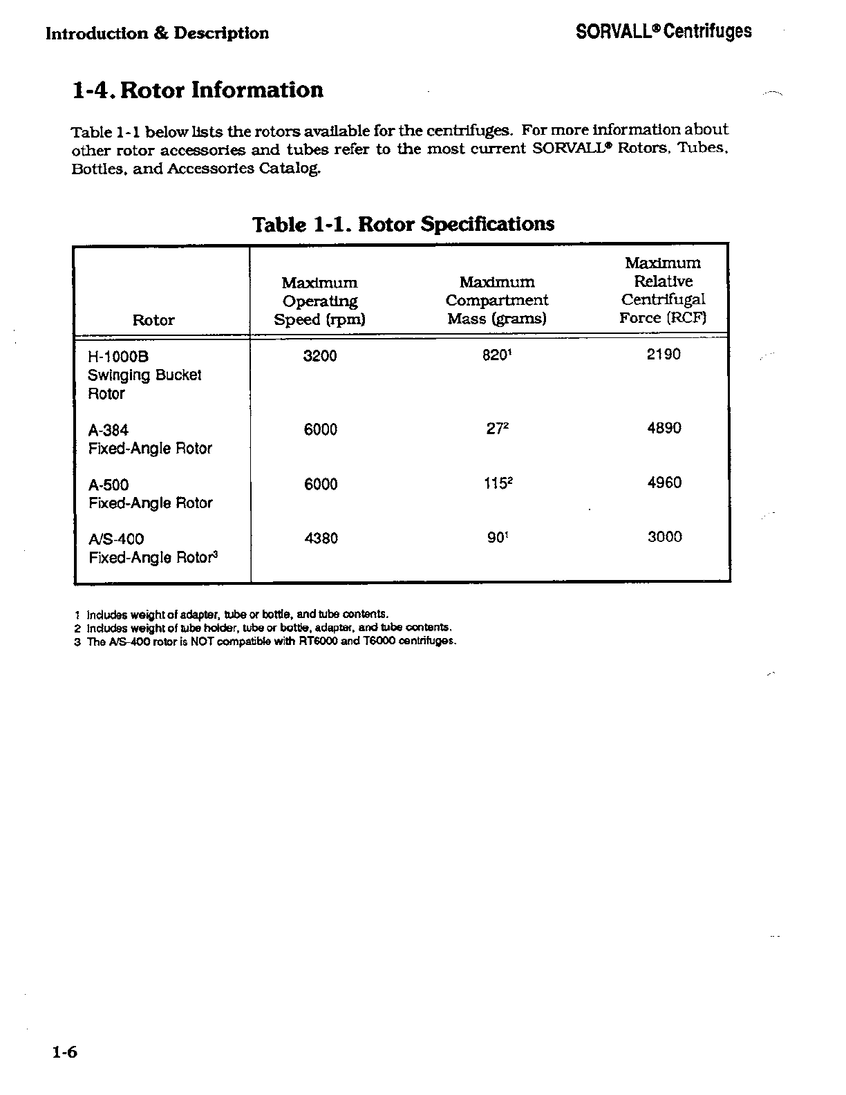
1-1. Rotor Specifications ................................ 1-6
3-1. Controls and Indicators for RT/T6000D and
RT/T6000B (SN 9101800 and Above) ................ .3-2
3-2. Controls and Indicators for RT/T6000B
(SNs Below 9101800) and RT/T6000 ................. .3-3
6-1. Printed Circuit Boards ............................. .6-5
7-1. RT6000 and T6000 Motor Controls P.C. Board
Component Identification .......................... .7-14
7-2. RT6000 Temperature Control P.C. Board
Component Identification ........................... 7-20
7-3. Suggested Spare Parts ............................. .7-32
7-4. Parts: RT6000 .................................... 7-33
7-5. Parts: T6000 ...................................... 7-37
7-6. Parts: Drive Assembly, PN 07588 ...................... 7-43
7-7. Refrigeration System: RT6000 Centrifuge ................ 7-46
7-8. Parts: Console Assembly ............................. 7-48
7-9. Parts: Lid Latch Mechanism ......................... .7-51
8-1. RT6000B and T6000B (SNs Below 9101800)
Motor Controls P.C. Board Component Identification ..... .8-18
8-2. RT6000B (SNs Below 9101800) Temperature Control
P.C. Board Component Identification ................. .8-26
8-3. Suggested Spare Parts ............................. .8-38
8-4. Parts: RT6000B (SNs Below 9101800) ................. .8-39
8-5. Parts: T6000B (SNs Below 9101800) ................... .8-43
8-6. Parts: Drive Assembly, PN 07884 ..................... .8-49
8-7. Refrigeration System: RT6000B Centrifuge .............. .8-52
8-8. Parts: Console Assembly ............................ .8-54
8-9. Parts: Lid Latch Mechanism ......................... .8-57
9-1. RT/T6000B (SN 9101800 and Above) and RT/T6000D
Control P.C. Board Component Identification, Rev. 1 ...... .9-25
9-2. RT/T6000B (SN 9101800 and Above) and RT/T6000D
Control P.C. Board Component Identification, Rev. 2 ...... .9-35
9-3. RT6000D Display P.C. Board Component Identification .... .9-44
9-4. T6000D Display P.C. Board Component Identification ..... .9-47
9-5. RT/T6000B (SN 9101800 and Above) Fault Light
P.C. Board Component Identification ................. .9-49
9-6. Suggested Spare Parts ............................. .9-68
9-7. Parts: RT6000B (SN 9101800 and Above) and RT6000D .... .9-69
9-8. Parts: T6000B (SN 9101800 and Above) and T6000D ...... .9-73
9-9. Parts: Drive Assembly, PN 07884 ..................... .9-79
9-10. Refrigeration System: RT6000B and RT6000D Centrifuge . . .9-82
9-11. Parts: Console Assembly (Below SN 9302370) ............ .9-84
9-12. Parts: Console Assembly (SN 9302370 and Above) ........ .9-87
9-13. Parts: Lid Latch Mechanism ......................... .9-90
VIII Rev. 7/93

SORVALL® Centrifuges Table of Contents
Illustrations
Page
Figure
3-1. Controls and Indicators for RT/T6000D and
RT/T6000B (SN 9101800 and Above) ................ .3-1
3-2. Controls and Indicators for RT/T6000B
(SNs Below 9101800) and RT/T6000 ................. .3-3
3-3. Location of Mechanical Override Loop .................. .3-9
4-1. Hinge Pin Lubrication .............................. .4-2
5-1. Latch Relay Parts Identification ...................... .5-3
5-2. Latch Solenoid Parts Identification .................... .5-4
5-3. Door Switch Parts Identification and Wire
Number Assignments ............................ .5-7
5-4. Refrigeration System Parts Identifications ............... .5-12
5-5. Cutting the Fan Shroud ............................ .5-14
5-6. Start Capacitor Assembly ........................... .5-15
5-7. Motor Parts Identification ........................... .5-18
5-8. Pulley Identification ............................... .5-18
5-9. Gyro Parts Identification ............................ .5-19
5-10. Pulley Alignment ................................. .5-21
5-11. Pulley Set Screw Seating ........................... .5-21
5-12. Drive Belt Replacement ............................ .5-24
5-13. Spring Tension Measurement ........................ .5-25
5-14. Motor Mounting Hardware .......................... .5-26
5-15. Motor Brush Assembly ............................. .5-28
5-16. Modified Connector P8 (Motor Control P.C. Board) ........ .5-33
5-17. Parts Location: Brake Resistor, Bridge Rectifier,
& Optical Pick-up ............................... .5-36
5-18. Parts Location, Motor and Gyro Assemblies ............. .5-38
5-19. Drive Assembly ................................... .5-42
5-20. Motor Assembly .................................. .5-46
6-1. Refrigeration System .............................. .6-2
6-2. Compressor Assembly Schematic ..................... .6-2
6-3. Electrical System Block Diagram ..................... .6-6
6-4. Power Switch (Circuit Breaker CB1) ................... .6-7
6-5. High Voltage Distribution ........................... .6-9
6-6. Low Voltage Distribution ............................ .6-9
6-7. Zero Speed Detection Circuit ........................ .6-11
6-8. Door Interlock Circuit .............................. .6-12
6-9. Timer Control Circuit .............................. .6-13
6-10. Speed Control Circuit .............................. .6-14
6-11. Temperature Control Circuit ......................... .6-16
6-12. Zero Crossing Circuit .............................. .6-16
6-13. SCR (Silicon Rectifier) Bridge Circuit .................. .6-17
6-14. SCR Phase Angle Control Circuit ..................... .6-18
6-15. Delayed Start Circuit .............................. .6-20
6-16. Slow Start PWM (Pulse Width Modulation) Circuit ........ .6-21

Table of Contents SORVALL® Centrifuges
Illustrations (continued)
Figure
6-17. Main Speed Pulse Width Modulation Circuit .........
6-18. Anticipation Component Voltage Equivalent .........
6-19. Closed-Loop Speed Control Circuit ................
6-20. Open-Loop Speed Control Circuit .................
6-21. Brake Circuit ................................
6-22. 200 RPM Switch ..............................
6-23. Zero Speed Detection Circuit ....................
6-24. Belt Tension Fault Circuit ......................
6-25. Imbalance Circuit .............................
6-26. Overtemperature Fault Circuit ...................
6-27. Undertemperature Fault Circuit ..................
6-28. Motor Thermal Overload Fuse ...................
7-1. System Schematic: RT/T6000 Centrifuges ..........
7-2. Wiring Diagram: RT/T6000 Centrifuges ............
7-3. Component Location: RT6000/T6000 Motor
Controls P.C. Board ..........................
7-4. Component Location: RT6000 Temperature
Control P.C. Board ...........................
7-5. Temperature Meter Adjustment ..................
7-6. Tachometer Zero Adjustment ....................
7-7. Parts: RT6000 ...............................
7-8. Parts: T6000 .................................
7-9. Drive Assembly, PN 07588 ......................
7-10. Refrigeration System: RT6000 Centrifuge ...........
7-11. Console Assembly .............................
7-12. Lid Latch Mechanism ..........................
8-1. System Schematic: RT/T6000B Centrifuges
(SNs Below 9101800) .........................
8-2. Wiring Diagram: RT/T6000B Centrifuges
(SNs Below 9101800) .........................
8-3. Schematic for RT/T6000B Centrifuges
(SNs Below 9101800) Motor Controls P.C. Board ....
8-4. Component Location: RT/T6000B (SNs Below 9101800)
Motor Controls P.C. Board .....................
8-5. Schematic for RT/T6000B Centrifuges
(SNs Below 9101800) Temperature Control P.C. Board
8-6. Component Location: RT/T6000B Centrifuges
(SNs Below 9101800) Temperature Control P.C. Board
8-7. Temperature Meter Adjustment ..................
8-8. Tachometer Zero Adjustment ....................
8-9. Parts: RT6000B (SNs Below 9101800) .............
8-10. Parts: T6000B (SNs Below 9101800) ...............
8-11. Drive Assembly ...............................
8-12. Refrigeration System: RT6000B Centrifuge ..........
Page
.6-23
.6-23
.6-25
.6-26
.6-26
.6-27
.6-28
.6-30
.6-31
.6-32
.6-33
.6-34
.7-3
.7-9
.7-13
.7-19
.7-22
.7-23
.7-35
.7-41
.7-45
.7-47
.7-50
.7-52
.8-3
.8-7
.8-11
.8-17
.8-23
.8-25
.8-29
.8-30
.8-41
.8-47
.8-51
.8-53
x

SORVALL® Centrifuges Table of Contents
Illustrations (continued)
Figure Page
8-13. Console Assembly ................................. .8-56
8-14. Lid Latch Mechanism .............................. .8-58
9-1. System Schematic, Rev. 1, RT/T6000B
(SN 9101800 and Above) and RT/T6000D ............. .9-3
9-2. System Schematic, Rev. 2, RT/T6000B
(SN 9101800 and Above) and RT/T6000D ............. .9-11
9-3. Wiring Diagram, RT/T6000B
(SN 9101800 and Above) and RT/T6000D ............. .9-19
9-4. Component Location: RT/T6000B (SN 9101800 and
Above) and RT/T6000D Control P.C. Board, Rev. 1 ....... .9-23
9-5. Component Location: RT/T6000B (SN 9101800 and
Above) and RT/T6000D Control P.C. Board, Rev. 2 ....... .9-33
9-6. Schematic for RT6000D Display P.C. Board ............. .9-42
9-7. Component Location: RT6000D Display P.C. Board ....... .9-43
9-8. Schematic forT6000D Display P.C. Board .............. .9-45
9-9. Component Location: T6000D Display P.C. Board ......... .9-46
9-10. Schematic for RT/T6000B Centrifuge
(SN 9101800 and Above) Fault Light P.C. Board ........ .9-48
9-11. Component Location: RT/T6000B Centrifuges
(SN 9101800 and Above) Fault Light P.C. Board ........ .9-49
9-12. Temperature Meter Adjustment ...................... .9-50
9-13. Tachometer Zero Adjustment ........................ .9-51
9-14. FTV Adjustment Measurement Point, Rev. 1 .............. .9-52
9-15. +24 Vdc Measurement Point. Rev. 1 .................... .9-52
9-16. Temperature Sensor Adjustment Measurement, Rev. 1 ..... .9-55
9-17. FTV Adjustment Measurement Point, Rev. 2 .............. .9-58
9-18. +24 Vdc Measurement Point, Rev. 2 .................... .9-58
9-19. Temperature Sensor Adjustment Measurement, Rev. 2 ..... .9-61
9-20. Parts: RT6000B (SN 9101800 and Above) and RT6000D .... .9-71
9-21. Parts: T6000B (SN 9101800 and Above) and T6000D ...... .9-77
9-22. Drive Assembly, PN 07884 .......................... .9-81
9-23. Refrigeration System: RT6000B & RT6000D Centrifuges . . . .9-83
9-24. Console Assembly (Below SN 9302329) ................. .9-86
9-25. Console Assembly (SN 9302329 and Above) ............. .9-89
9-26. Lid Latch Mechanism .............................. .9-91
Rev. 7/93 xi/xii


Contents
Section 1, Introduction & Description
Paragraph
1 -1. Introduction
a. Intended Use of the Manual
b. Service Decontamination Policy
c. Warranty Responsibility
1-2. Centrifuge Description
1-3. Centrifuge Specifications
1-4. Rotor Information

SORVALL® Centrifuges Introduction & Description
Section 1
INTRODUCTION & DESCRIPTION
This manual is a service guide for the SORVALL* RT6000D, T6000D, RT6000B, T6000B,
RT6000, and T6000 Tabletop Centrifuges*. It contains descriptive information; preven¬
tive maintenance procedures; mechanical and electrical theories of operation; procedures
for repairs, replacements, and calibrations; and an illustrated parts list for ordering
replacement parts.
1 -1. Introduction
a. Intended Use of the Manual
This manual is for qualified service personnel who are familiar with factory methods
for performing repairs, adjustments and calibrations.
Warnings. Cautions, and Notes are used throughout this manual to emphasize
Important and critical instructions. Service personnel are expected to be familiar with
their meaning (see page 11) and to read them before servicing the centrifuge.
b. Service Decontamination Policy
If a centriiuge or rotor that has been used with radioactive or pathogenic material
requires servicing by Du Pont personnel, either at the customer's laboratory or at a
Du Pont facility, comply with the following procedure to ensure the safety of all
personnel:
1. Clean centrifuge or rotor to be serviced of all encrusted material and decontami¬
nate it prior to servicing by the Du Pont representative or returning it to the Du
Pont facility. There must be no radioactivity detectable by survey equipment.
References to all models of the centrifuge will be designated "the centrifuges.' References to a particular model will be designated
by the model number (e.g. RT6000D).
1-1

introduction & Description SORVALL® Centrifuges
The SORVALL* Rotors. Tubes. Bottles, and Accessories Catalog contains descrip¬
tions of commonly used decontamlnatlon methods and a chart showing method
compatibility with various materials. The maintenance section of the centrifuge
or rotor instruction manual contains specific guidance about cleaning and
decontamination methods appropriate for the centrifuge or rotor it describes.
Clean and decontaminate your centrifuge or rotor as follows:
For lowspeed, superspeed, and SUPRAspeed* Jloor model centrifuges:
a. Remove rotor from the rotor chamber.
b. Remove, wash. and decontaminate motor sealing gasket and pad.
c. Drain line plugs and clean drain line.
d. Decontaminate lid, rotor chamber, and drive using an appropriate method.
e. Remove all encrusted material from around the motor and drive assemblies.
For ultraspeed centrifuges:
a. Remove rotor from the rotor chamber.
b. Decontaminate door and rotor chamber using an appropriate method.
For tdbletop centrifuges:
a. Remove rotor from the rotor chamber.
b. Remove motor sealing gasket and wash with appropriate decontaminant.
c. Decontaminate cover, bowl. and drive using an appropriate method.
For rotors;
a. Remove tubes, bottles, and adapters from the rotor and decontaminate rotor
using an appropriate method. If tubes or rotor caps are stuck in the rotor,
or the rotor lid is stuck, notify Du Pont representative; be prepared with the
name and nature of the sample so the Du Pont Chemical Hazards Officer can
decide whether to authorize the rotor's return to a Du Pont facility.
2. Complete and attach Decontamination Information Certificate (SORVALL® Prod¬
ucts Form No. IPDP-59 or E53603) to the centrifuge or rotor before servicing or
return to Du Pont facility. If Certificate is not available, attach a written statement
verifying decontamination (what was contaminant and what decontamination
method was used).
If the centrifuge or rotor must be returned to a Du Pont facility:
1. Contact your Du Pont representative to obtain a Return Service Order Number
(RSO#); be prepared with the name and serial number of the centrifuge or rotor
and the repairs required.
2. Send item(s) with the RSO# clearly marked on the outside of packaging to the
address obtained from your Du Pont representative.
1-2

SORVALL® Centrifuges Introduction & Description
NOTE
United States federal regulations require that parts and instruments must
be decontaminated before being transported.
If a centrifuge or rotor to be serviced does not have a Decontamlnatlon Information
Certificate attached and. In Du Font's opinion presents a potential radioactive or
biological hazard, the Du Pont representative will not service the equipment until
proper decontamlnatlon and certification Is complete. IfDu Pont receives a centrifuge
or rotor at its Service facilities which. In its opinion, is a radioactive or biological
hazard, the sender will be contacted for instructions as to disposition of the
equipment. Disposition costs will be bome by the sender.
Decontamlnatlon Information Certificates are included in the back of this manual.
Additional certificates are available from the local Account or Service Representative.
In the event these certificates are not available, a written statement certifying that the
unit has been properly decontaminated and outlining the procedures used will be
acceptable.
NOTE
The Service Representative will note on the Customer Service Repair
Report if decontamination was required and, if so, what the contaminant
was and what procedure was used. If no decontamination was required, it
will be so stated.
c. Warranty Responsibility
Whenever service of the centrifuge is attempted by anyone other than an employee of
Du Pont or an authorized representative, the individual is assuming the risk of voiding
the centrifuge warranty, which is as follows:
E. I. du Pont de Nemours and Company makes no warranty of any kind, expressed
or implied, except as stated in this warranty policy.
The SORVALL* RT6000D. T6000D. RT6000B, T6000B, RT6000, and T6000 Centri¬
fuges are warranted to be free from defects in materials and workmanship for a period
of one year from the date of delivery. Du Pont will repair or replace and return free of
charge any part which is returned to its factory within said period, transportation
prepaid by user, and which is found upon inspection to have been defective in
materials or workmanship. This warranty does not apply to any damage to any
Instrument resulting from: normal wear and tear; misuse; abuse; use of electric
currents or circuits other than those specified on the plate affixed to the centrifuge:
or use of any rotor other than those intended for use in the instrument.
Du Pont reserves the right to change, alter, modify or improve its centrifuges without
any obligation whatsoever to make corresponding changes to any centrifuge previ¬
ously sold or shipped.
1-3

Introduction & Description SORVALL® Centrifuges
THE FOREGOING OBLIGATIONS ARE IN LIEU OF ALL OTHER OBLIGATIONS AND
LIABILITIES INCLUDING NEGLIGENCE AND ALL WARRANTIES. OF MERCHANTA-
BILTIY OR OTHERWISE. EXPRESSED OR IMPLIED IN FACT OR BY LAW. AND STATE
OUR ENTIRE AND EXCLUSIVE UABILTIYAND BUYER'S EXCLUSIVE REMEDY FOR
ANY CLAIM OR DAMAGES IN CONNECTION WITH THE SALE OR FURNISHING OF
GOODS OR PARTS, THEIR DESIGN. SUITABILITY FOR USE. INSTALLATION OR
OPERATION. Du Font WILL IN NO EVENT BE LIABLE FOR ANY SPECIAL OR
CONSEQUENTIAL DAMAGES. AND OUR LIABILITY UNDER NO CIRCUMSTANCES
WILL EXCEED THE CONTRACT PRICE FOR THE GOODS FORWHICH LIABILITY IS
CLAIMED.
1-2. Centrifuge Description
The centrifuge models described in this manual are grouped into four categories, which
are distinguished from one another as follows:
• RT6000 and T6000: open-loop speed control, analog displays, square-shaped
drive spindle (does not accept A/S-400 rotor)
• RT6000B and T6000B (Serial Numbers below 9101800): open-loop speed
control, analog displays, diamond-shaped drive spindle (accepts A/S-400 rotor)
• RT6000B and T6000B (Serial Number 9101800 and above): closed-loop speed
control, analog displays, diamond-shaped drive spindle; also, the T6000B has a
smaller cabinet than the RT6000B.
• RT6000D and T6000D: closed-loop speed control, digital displays, diamond-
shaped drive spindle; also, the T6000D has a smaller cabinet than the RT6000D.
Also note that there is a significant difference in cabinet design between the first two and
last two categories of centrifuge: the RT/T6000 and the RT/T6000B (SNs below 9101800)
have medium gray cabinet panels and a black control panel; the RT/T6000B (SN 9101800
and above) and the RT/T6000D have light gray cabinet panels and a light gray control
panel.
The RT6000D. RT6000B (all serial numbers), and RT6000 combine features oftabletop
centrifuges with those of larger refrigerated centrifuges into a compact tabletop centrifuge.
They are similar to other SORVALL® Tabletop Centrifuges, with an added refrigeration
system that consists of an evaporator/rotor chamber and a low-temperature condensing
unit. The system is designed to maintain temperature within 1°C while in the operating
range of -5°C to +25°C. The T6000D, T6000B (all serial numbers), and T6000 are non-
refrigerated tabletop centrifuges.
All centrifuge models feature a see-through chamber door that allows rotor calibration and
visual inspection of a run in progress. The chamber door is counterbalanced for easy
opening and safe closing. The lid latch is locked manually by turning the door release knob
counterclockwise. A mechanical interlock engages when a run is started, preventing the
chamber door from being opened during operation.
1-4

SORVALL® Centrifuges Introduction & Description
1-3. Centrifuge Specifications
• Maximum Speed* ..........................6000 rpm**
• Operating Temperature
Range (Refrigerated
centrifuges only) .......................... .-5°C to +25°C
• Maximum heat output during
operation ............................ 1.76 kW (6000 Btu/h)—Refrigerated
centrifuges
0.88 kW (3000 Btu/h)— Non-refriger-
ated centrifuges
• Electrical Requirements:
Refrigerated centrifuges ........................115 Vac, 60 Hz, 15 A, single phase
220 Vac, 50 Hz, 8 A, single phase
Non-refrigerated centrifuges ....................115 Vac, 60 Hz, 8 A, single phase
220 Vac, 50 Hz, 4 A, single phase
Power Receptacles:
115 Vac Receptacle ........................... NEMA 5-15R or equivalent
220 Vac Receptacle ...........................NEMA 6-15R or equivalent
• Dimensions:
Width ......................................81 cm (32 inches)
(T6000D and T6000B,
SN 9101800 and above only) .................66 cm (26 inches)
Depth ......................................64 cm (25 inches)
Height ......................................32 cm (12.5 inches)
• Mass (Weight): ...............................85 kg (187 Ib)
(T6000D and T6000B,
SN 9101800 and above only) .................78 kg (160 Ib)
" Maximum speed is dependent on rotor and line voltage.
"Speed in revolutions per minute (rpm) is related to angular velocity, <u, according to the following:
<a = (^(il)" (rpm) (0.10472)
Where co= rad/s. All further references in this manual to speed will be designated as rpm.
1-5

Introduction & Description SORVALL® Centrifuges
1-4. Rotor Information
Table 1-1 below lists the rotors available for the centrifuges. For more information about
other rotor accessories and tubes refer to the most current SORVALL* Rotors, Tubes,
Bottles, and Accessories Catalog.
Table 1-1. Rotor Specifications
Rotor
Maximum
Operating
Speed (rpm)
Maximum
Compartment
Mass (grams)
Maximum
Relative
Centrifugal
Force (RCF)
H-1000B
Swinging Bucket
Rotor
A-384
Fixed-Angle Rotor
A-500
Fixed-Angle Rotor
A/S-400
Fixed-Angle Rotor3
3200
6000
6000
4380
8201
272
1152
901
2190
4890
4960
3000
1 Includes weight of adapter, tube or bottle, and tube contents.
2 Includes weight of tube holder, tube or bottle, adapter, and tube contents.
3 The A/S-400 rotor is NOT compatible with RT6000 and T6000 centrifuges.
1-6

Contents
Section 2, Installation
Paragraph
2-1. Inspection
2-2. Location and Installation
2-3. Electrical Requirements
This manual suits for next models
2
Table of contents
Other Sorvall Laboratory Equipment manuals