Solax TRIPLE POWER T-BAT LR25 User manual

T-BAT LR25
T-BAT LR36
User Manual
www.solaxpower.com


I
STATEMENT
Copyright
Copyright © SolaX Power Technology (Zhejiang) Co., Ltd. All rights reserved.
No part of this manual may be reproduced, transmitted, transcribed, stored in a retrieval
system, or translated into any language or computer language, in any form or by any
means without the prior written permission of SolaX Power Technology (Zhejiang) Co., Ltd.
Trademarks
and other symbol or design (brand name, logo) that distinguishes the products or
services offered by SolaX has been trademark protected. Any unauthorized use of above
stated trademark may infringe the trademark right.
Notice
All or part(s) of the products, features and services described in this document may not be
within your scope of purchase or usage. Unless otherwise specified in the contract, the
contents, information and recommendations in this document are provided as is, SolaX
makes no kind of warranties, guarantees or representations expressly or implicitly.
The content of the documents is continually reviewed and amended, where necessary.
However, discrepancies cannot be excluded. SolaX reserves the right to make
improvements or changes in the product(s) and the program(s) described in this manual at
any time without the prior notice.
The images contained in this document are for illustrative purposes only and may vary
depending on product models.
Please visit the website www.solaxpower.com of SolaX Power Technology (Zhejiang) Co.,
Ltd. for more information.
SolaX reserves all the right for the final explanation.

II
About This Manual
Scope of Validity
This manual is an integral part of T-BAT Series. It describes the installation,
electrical connection, commissioning, maintenance and troubleshooting
of the product. Please read it carefully before operating.
Battery Module
T-BAT LR25
T-BAT LR36
Note:
In the case of rack or cabinet installation, the whole battery system
contains battery module(s) and rack (or cabinet). In the case of wall
mounting, it contains battery module(s) only. For details, please refer to
the Chapter 11 “Technical Data”.
Target Group
The installation and maintenance can only be performed by qualified
personnel who
• Are licensed and/or satisfy state and local jurisdiction regulations.
• Have good knowledge of this manual and other related documents.

III
Conventions
The symbols that may be found in this manual are defined as follows.
Symbol Description
DANGER Indicates a hazardous situation which, if not avoided,
will result in death or serious injury.
WARNING Indicates a hazardous situation which, if not avoided,
could result in death or serious injury.
CAUTION! Indicates a hazardous situation which, if not avoided,
could result in minor or moderate injury.
NOTICE! Provides tips for the optimal operation of the
product.
Change History
Version 00 (Jul. 11, 2023)
Initial release

IV
Table of Contents
1 Safety ..........................................................................................................1
1.1 General Safety ....................................................................................................................1
1.2 General Safety Precautions ............................................................................................2
1.3 Battery Handling Guide....................................................................................................2
1.4 Response to Emergency Situations..............................................................................3
2 Product Overview ....................................................................................5
2.1 System Description ...........................................................................................................5
2.2 Appearance .........................................................................................................................5
2.2.1 Weight and Dimensions .....................................................................................6
2.2.2 Battery Module (T-BAT LR25/ T-BAT LR36)...................................................8
2.2.3 Indicators ................................................................................................................10
2.2.4 Symbols on the Label .........................................................................................13
2.3 Features ................................................................................................................................14
2.4 Certifications.......................................................................................................................14
3 Transportation and Storage ...................................................................15
4 Preparation before Installation..............................................................16
4.1 Selection of Installation Location .................................................................................16
4.1.1 Environment Requirement ................................................................................16
4.1.2 Installation Carrier Requirement......................................................................17
4.1.3 Clearance Requirement .....................................................................................18
4.2 Tools Requirement............................................................................................................20
4.3 Additionally Required Materials .....................................................................................20
5 Unpacking and Inspection .....................................................................21
5.1 Unpacking............................................................................................................................22
5.2 Scope of Delivery...............................................................................................................23
6 Mechanical Installation ...........................................................................27
6.1 Installation Options ...........................................................................................................27
6.2 Installation Procedure ......................................................................................................28
6.2.1 Installation Procedure with Rack .....................................................................29
6.2.2 Installation Procedure with Cabinet ...............................................................34
6.2.3 Wall Mounting .......................................................................................................42
7 Wiring..........................................................................................................48
7.1 PE Connection ...................................................................................................................48

V
7.2 Communication Connection (connecting to inverter) ..........................................50
7.3 Details of Cables ................................................................................................................52
7.4 Wiring Procedure ...............................................................................................................54
7.4.1 Wiring Procedure about Rack Installation.....................................................54
7.4.2 Wiring Procedure about Cabinet Installation...............................................58
7.4.3 Wiring Procedure about Wall Mounting ........................................................63
8 System Commissioning..........................................................................67
8.1 Checking before Power-on ............................................................................................67
8.2 Powering on the System..................................................................................................67
9 Troubleshooting and Maintenance ......................................................68
9.1 Power off the System .......................................................................................................68
9.2 Troubleshooting.................................................................................................................69
9.3 Maintenance........................................................................................................................73
10 Decommissioning....................................................................................74
10.1 Disassembling the Battery ..............................................................................................74
10.2 Packing..................................................................................................................................76
10.3 Disposing of the Rechargeable Battery.......................................................................76
11 Technical Data ..........................................................................................77


1
1 Safety
1.1 General Safety
The series rechargeable battery is well designed and tested to meet all applicable states and
international safety standards. However, like all electrical and electronic equipment, safety
precautions must be observed and followed during the installation of the rechargeable
battery to reduce the risk of personal injury and to ensure a safe installation.
Before installing the device, carefully read, fully understand and strictly follow the detailed
instruction of the
User Manual
and other related regulations. And the safety instructions in
this document are only supplements to local laws and regulations.
SolaX shall not be liable for any consequences caused by the violation of the storage,
transportation, installation, and operation regulations specified in this document, including,
but not limited to:
• Rechargeable battery damage due to force majeure, such as earthquake, flooding,
thunderstorm, lighting, fire hazard, volcanic eruption, overvoltage, etc.
• Rechargeable battery damage due to man-made cause
• Rechargeable battery used or operated against any items in local policy
• Failure to follow the operation instructions and safety precautions on the product
and in this document
• Installation and use under improper environment or electrical condition
• Unauthorized modifications to the product or software
• Rechargeable battery damage caused during transportation by the customer
• Storage conditions that do not meet the requirements specified in this document
• Failure to adequately maintain the equipment. An on-site inspection should be
carried out by a qualified technician after 120 months of continuous use. If more
than 120 months have been passed since the date of commissioning, or the user
cannot prove that the equipment has been adequately maintained
• Use of incompatible inverters or devices
• Installation and commissioning operated by unauthorized personnel who are not
licensed and /or satisfy state and local jurisdiction regulations.

2
Safety
1.2 General Safety Precautions
• Overvoltage or wrong wiring may damage the battery module and cause
combustion which may be extremely dangerous;
• Leakage of electrolytes or flammable gas may be occurred due to any type of
product breakdown;
• Do not install the battery module in places where flammable and combustible
materials are stored, and in which an explosive atmosphere is present;
• The battery module wiring must be carried out by qualified personnel;
• Battery module must be serviced by qualified personal;
• Ensure that the grounding cable is connected before handling the battery
module.
1.3 Battery Handling Guide
Do's
• DO keep the battery module away from flammables materials, heat sources, and
water sources;
• DO keep the battery module out of reach of children and animals;
• DO practice proper battery storage by keeping the battery module in a clean
environment, free of dust, dirt and debris;
• DO store the battery module in a cool and dry place;
• DO seal the outer cable connection hole to prevent ingress of foreign objects;
• DO confirm that the wiring of the device must be correct;
• DO install the device according to the local standards and regulations.
Don'ts
• DON'T expose the battery module to an open flame, or the temperature in excess
of 140°F/60°C;
• DON'T store or install the battery module in direct sunlight;
• DON'T install or operate the battery module in places where there is excessive
moisture or liquids;
• DON'T place the battery module in a high-voltage environment;
• DON'T disconnect, disassemble or repair the device by unqualified personnel.
Only a qualified personnel is allowed to handle, install and repair the device;
• DON'T damage the device by dropping, deforming, impacting, cutting or

3
Safety
penetrating with a sharp object. Otherwise, it may cause a fire or leakage of
electrolytes;
• DON'T touch the device if liquid spill on it. There is a risk of electric shock;
• DON'T step on the packaging or the device may be damaged;
• DON'T place any objects on top of the battery module;
• DON'T charge or discharge a damaged battery module;
• DON'T dispose of the battery module in a fire. It may cause leakage or rupture;
• DON'T mix different types or makes of the battery module. It may cause leakage
or rupture, resulting in personal injury or property damage.
1.4 Response to Emergency Situations
In case the battery module leaks electrolyte or any other chemical materials, or gas
may be generated due to the leakage of battery module, be sure to avoid contact
with the discharge at all times. In case of accidentally coming into contact with them,
please do as follows:
• In case of inhalation: Leave the contaminated area immediately, and seek medical
attention at once;
• In case of contact with eyes: Rinse eyes with running water for 15 minutes, and
seek medical attention;
• In case of contact with skin: Wash the contacted area thoroughly with soap, and
seek medical attention;
• In case of ingestion: Induce vomiting, and seek medical attention.
If a fire breaks out where the battery module is installed, please do as follows:
• In case the battery module is charging when the fire breaks out, provide it is
safe to do so, disconnect the battery module circuit break to shut off the power
charge;
• In case the device is not on fire yet, use a Class ABC fire extinguisher or a carbon
dioxide extinguisher to extinguish the fire;
• If the battery module catches fire, do not try to put out the fire, and evacuate
immediately.
• The battery module may catch fire when it is heated above 302°F/60°C; and in
case of catching fire, it will produce noxious and poisonous gas, DO not approach
and keep away.

4
Safety
Effective ways to deal with accidents
• In case of the damaged battery module, place it into a segregated place, and call
the local fire department at the place where the user lives or qualified personnel.
• If any part of the battery module, or wiring is submerged, DO stay out of the
water and DON'T touch anything; If the battery module gets wet, DON'T touch it.
• If the battery module is damaged, DON'T use it. Otherwise, it may result in both
personal injury and property damage.
• DON'T use the submerged battery module again, and contact the qualified
personnel for assistance.
• DO contact SolaX immediately for assistance if the user suspects that the battery
module is damaged.
WARNING!
• Do not crush or impact battery, and always dispose of it according to relevant safety
regulations.
• The battery module may catch fire when heated above 150°C/302°F.
• In case of catching fire, the battery module will produce noxious and poisonous
gases, and please keep away the battery.
• Damaged batteries may leak electrolyte or produce flammable gas. If users suspect
that the battery is damaged, please immediately contact SolaX for advice and
information.
• All operations of T-BAT SYS-LR relating to electrical connection and installation must
be carried out by qualified personnel.
CAUTION!
• If the battery module is not installed within a month after receipt, it must be charged
for maintenance. Non-operational batteries should be discarded according to the
local regulations.
5
2 Product Overview
2.1 System Description
A battery module is a type of electrical battery which can charge or discharge loads.
There are three installation options, such as rack installation, cabinet installation, and floor
mounting, that a user can select from.
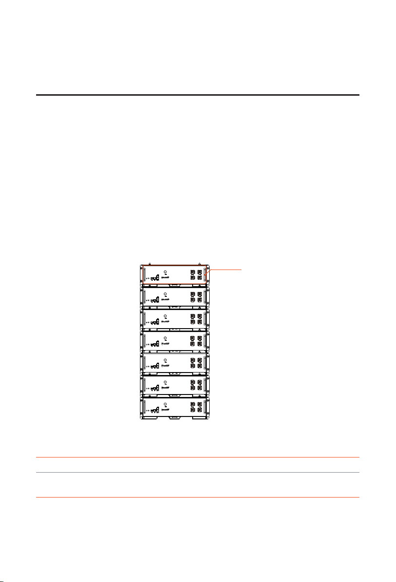
2.2 Appearance
Even if the silkscreen on different models of battery modules (T-BAT LR25 and T-BAT LR36)
is different, the final installation effect drawing is the same.
The following figure takes the rack installation as an example.
Electrical
connection area
Figure 2-1 Appearance
Table 2-1 Description of appearance
Item Description
Electrical
connection area
Including BAT+/BAT- ports, communication port, BMS port,
grounding port. Please refer to for details.
6
Product Overview
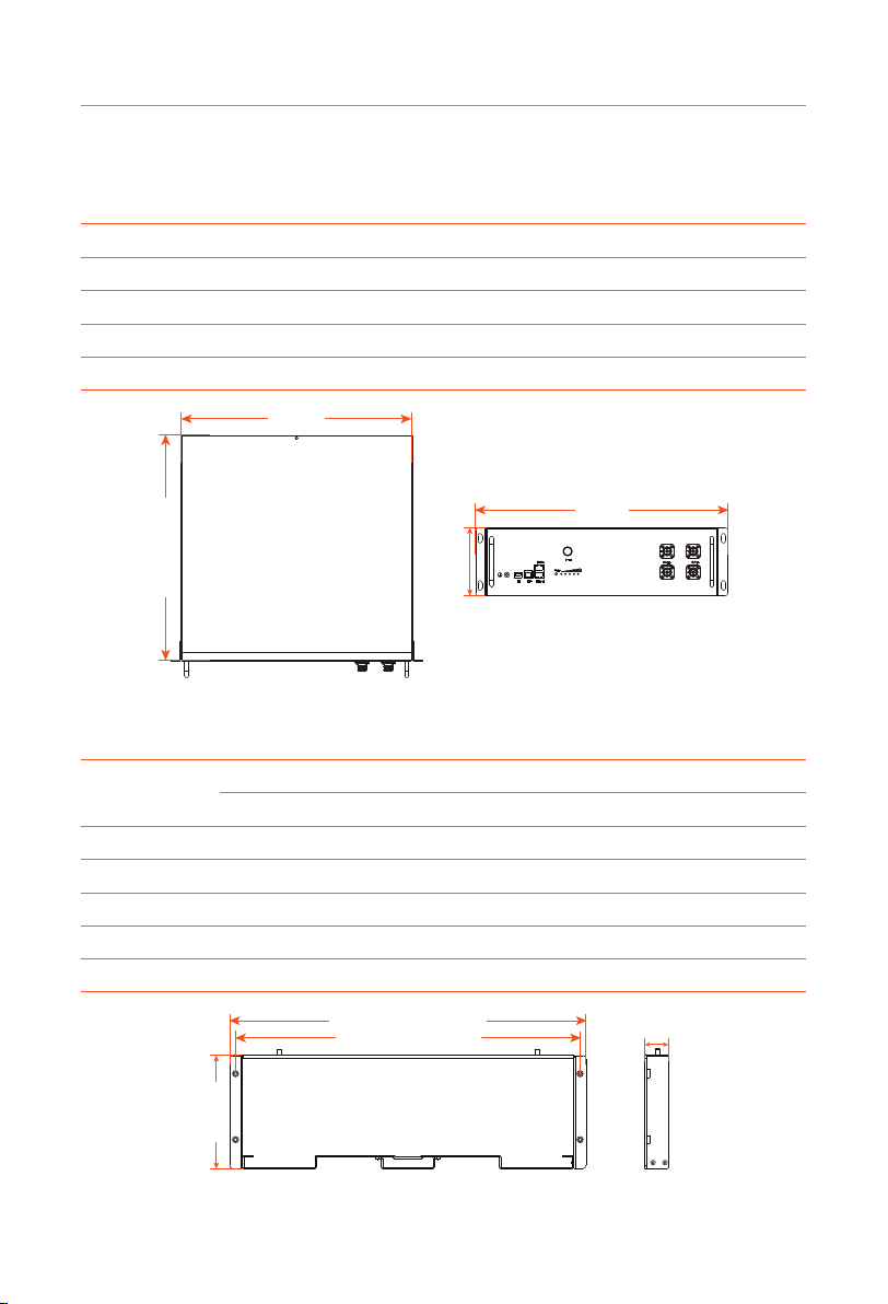
2.2.1 Weight and Dimensions
Table 2-2 Weight and Dimension of Battery Module
Battery Module (T-BAT LR25) Battery Module (T-BAT LR36)
Length (mm) 442.00 442.00
Width (mm) 430.00 430.00
Height (mm) 130.00 130.00
Net weight (kg) 28.00 32.00
442 mm
430 mm
481 mm
130 mm
Figure 2-2 Dimension: Battery module (T-BAT LR25/ T-BAT LR36)
Table 2-3 Weight and Dimension of Rack and Cabinet
Rack Cabinet
Front Support Rear Support Metal Plate 22U 42U
Length (mm) 481.00 448.00 426.50 600.00 600.00
Width (mm) 32.00 32.00 34.00 600.00 600.00
Height (mm) 153.50 153.50 8.00 1161.00 2050.00
Net weight (kg) (In total) 1.8 / /
Remark 1U = 4.445 cm
465 mm
481 mm 32 mm
153 mm
Figure 2-3 Dimension: Front support
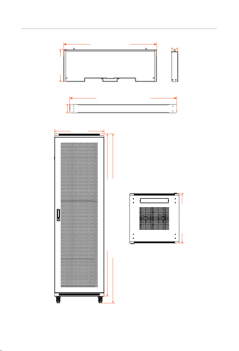
7
Product Overview
448 mm 32 mm
153 mm
Figure 2-4 Dimension: Rear support
426.5 mm
34 mm
Figure 2-5 Dimension: Metal plate
600 mm
1970 mm
2050 mm
600 mm
Figure 2-6 Dimension: Cabinet

8
Product Overview
2.2.2 Battery Module (T-BAT LR25/ T-BAT LR36)
A B C D E F G H
Figure 2-7 Battery module (T-BAT LR25/ T-BAT LR36)
Table 2-4 Description of ports and keys
Item Description
A Grounding port: Connect to the grounding port of the battery module or BMS.
B“DIP Switch”: Realize battery's parallel function (a reserved function).
C BMS port: Connect to the BMS port on the inverter.
D
Link in port: Connect to the "Link out" port of the neighbouring battery module
(if any), or it doesn't need to be connected.
Link out port: Connect to the "Link in" port of the neighbouring battery module
(if any), or it doesn't need to be connected.
E“Indicators”: A light that prompts the user to the status of the device.
F Power button: Start/shut down system.
GBAT+ port: Connect to the BAT+ port of the inverter. These two terminals'
function is the same.
HBAT- port: Connect to the BAT- port of the inverter. These two terminals'
function is the same.

9
Product Overview
DIP Switch
A DIP Switch is actually a set of small manual electronic switches that are designed to be
packaged with other circuits. It is currently equipped with the battery module.
The location of the DIP switch and the factory defaults are shown as below.
Figure 2-8 DIP Switch
OFF
ON
Default Configuration
1 2 3 4 5
A reserved function
Terminal resistance
Figure 2-9 Default configuration
NOTICE!
• In the case of one tower, there is only one master battery module (always the
uppermost battery module). While the master battery module connects to the
inverter, please confirm that the DIP switch 5 must stay in the ON position, as well
as the DIP switch 5 on the rest of the battery modules in the ON positions. Usually,
the DIP switch 5 will be slid to the ON position in the factory settings.
• In the case of more than two towers, except that the master battery module (always
the uppermost battery module) of the last tower shall be slid to the ON position,
the Dip switch 5 on the rest of the master battery modules shall be flipped up to the
OFF positions. Regarding the Dip switch 5 on the rest of the battery modules, please
confirm that they are in the ON positions. Usually, the DIP switch 5 will be slid to the
ON position in the factory settings.
• To adjust the DIP switch, a small flat-head screwdriver should be prepared by the
users themselves. Do not use a pencil. Graphite from the pencil is conductive and
may damage the DIP switch.

10
Product Overview
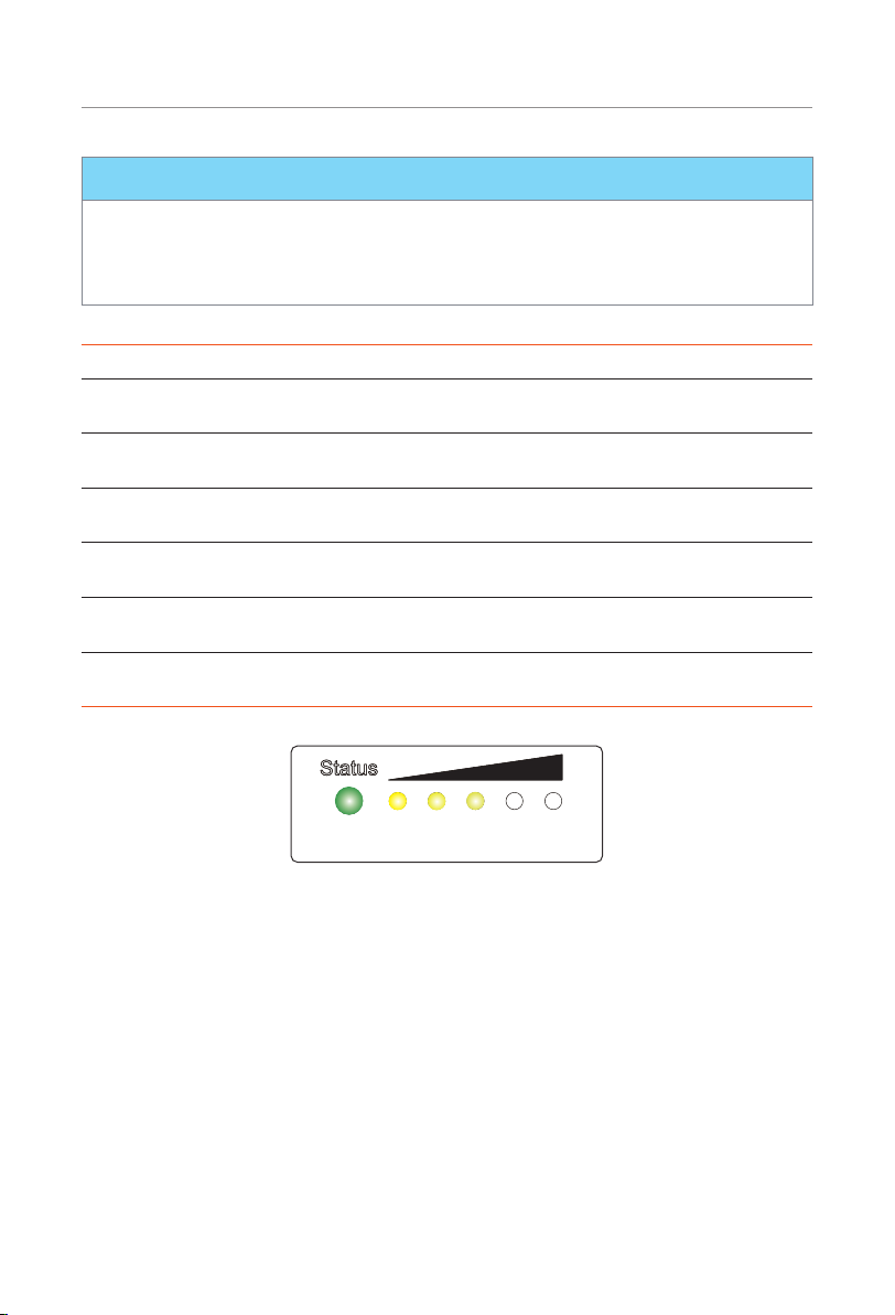
2.2.3 Indicators
The power indicators show the current battery percentage. There are six indicators on the
battery module, one status light and five SOC power indicators.
Status Light
SOC power indicators
20% 40% 60% 100%80%
SOC1 SOC2 SOC3 SOC4 SOC5
Figure 2-10 Indicators
Table 2-5 Definition of indicators
Status Description
Start up After pressing and holding the POWER button for more than 1 second,
the function “Self Test” will be performed. When the Self Test is
completed successfully, the status light will flash green light, and the
SOC power indicators will remain on solid yellow light.
Shut down After pressing and holding the POWER button for more than 3 seconds,
the status light will remain on solid yellow light, and the SOC power
indicators will remain on solid yellow light, and then all indicators are
off.
Standby The status light will come on green light. At the meantime, the SOC
power indicators will come on solid yellow light.
Charging The status light will flash green light every 1 second. Regarding the SOC
power indicators, please refer to “Indicator information while charging”.
Discharging The status light will flash green light every 1 second. Regarding the
SOC power indicators, please refer to “Indicator information while
discharging”.
Fault In the case of failure, the status light will flash red light every 3 seconds.
At the meantime, the SOC power indicators will remain on solid yellow
light.
Black Start For details, please refer to “Black Start”.
11
Product Overview
NOTICE!
• The function of Self Test will be performed when users turn the system on, with a
duration of 10 seconds. In the meantime, the status light will remain on solid yellow
light, and the SOC power indicators will remain on solid yellow light based on their
actual remaining capacity.
Table 2-6 Indicator information while charging
SOC value Status light SOC1 SOC2 SOC3 SOC4 SOC5
0% = SOC Flashing
green light Light off Light off Light off Light off Light off
0% < SOC < 20% Flashing
green light Flash Light off Light off Light off Light off
SOC < 40% Flashing
green light Flash Flash Light off Light off Light off
SOC < 60% Flashing
green light Flash Flash Flash Light off Light off
SOC < 80% Flashing
green light Flash Flash Flash Flash Light off
SOC ≥ 81% Flashing
green light Flash Flash Flash Flash Flash
20% 40%
SOC1 SOC2 SOC3 SOC4 SOC5
60% 80% 100%
Figure 2-11 Charging
If the battery level is at 60%, the SOC power indicators will show as follows:
• The first three SOC power indicators (SOC1, SOC2 and SOC3) will flash yellow light every
1 second;
• The remaining SOC power indicators (SOC4 and SOC5) will be off.

12
Product Overview
Table 2-7 Indicator information while discharging
SOC value Status light SOC1 SOC2 SOC3 SOC4 SOC5
SOC ≥ 80% Flashing
green light Light on Light on Light on Light on Light on
SOC ≥ 60% Flashing
green light Light on Light on Light on Light on Light off
SOC ≥ 40% Flashing
green light Light on Light on Light on Light off Light off
SOC ≥ 20% Flashing
green light Light on Light on Light off Light off Light off
SOC ≥ 0% Flashing
green light Light on Light off Light off Light off Light off
20% 40%
SOC1 SOC2 SOC3 SOC4 SOC5
60% 80% 100%
Figure 2-12 Discharging
If the battery level is at 60%, the SOC power indicators will show as follows:
• The first three SOC power indicators (SOC1, SOC2, and SOC3) will remain on solid
yellow light;
• The remaining SOC power indicators (SOC4 and SOC5) will be off.
Black Start
The equipment can provide Black Start capacity, meaning that our energy storage inverter
and battery can continue to run even if the power grid and photovoltaic panel are out of
service. The startup procedure for Black Start is as follows:
• First stage: in case of pressing and holding the POWER button for less than 15
seconds, the status light will come on solid yellow light in the first 11 seconds and
then turn to solid green light in the last 4 seconds, and the SOC power indicators
will come on solid yellow light based on the actual remaining capacity.
• Second stage: after pressing and holding the POWER button for more than 15
seconds, the status light will flash yellow light every 1 second, and all the SOC
power indicators will remain on solid yellow light based on the actual remaining
capacity.
• Finally, release the POWER button.
Other manuals for TRIPLE POWER T-BAT LR25
1
This manual suits for next models
1
Table of contents
Other Solax Batteries Pack manuals


