manuals.online logo
Brands
  1. Home
  2. •
  3. Brands
  4. •
  5. Sokkia
  6. •
  7. Measuring Instrument
  8. •
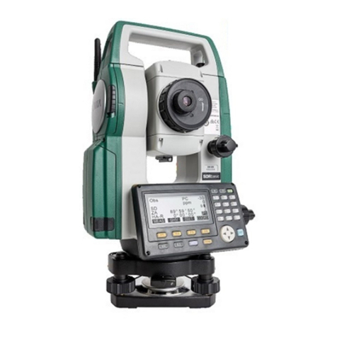
  9. Sokkia iM-100 Series Installation guide

Sokkia iM-100 Series Installation guide

Battery Charging
The battery (BDC70) was not charged at the factory. Charge the battery
fully before using the instrument.
1. Connect the power cable to the charger and plug the charger into the
wall outlet.
2. Mount the battery in the charger by matching the grooves on the bat-
tery with the guides on the charger. When charging starts, the lamp
starts blinking.
3. The lamp lights when charging is finished.

• Be sure to charge the battery within the charging temperature range.
Charging temperature range: 0 to 40°C
Installing the Battery
1. Slide down the catch on the battery
cover to open.
2. Checking the terminal side on the
battery, insert the battery as shown.

• Do not insert the battery inclined. Doing so may damage the
instrument or battery terminals.
3. Close the battery cover. A click is heard when the cover is secure.
Upon opening, make sure that all the following are included.
SURVEYING INSTRUMENTS
iM-100
series
Quick Manual
1019175-01-A
Standard Package Components
For the safe use of the product and prevention of injury to operators and other
persons as well as prevention of property damage, items which should be
observed are indicated by an exclamation point within a triangle used with
WARNING and CAUTION statements in this operator’s manual.
The definitions of the indications are listed below. Be sure you understand
them before reading the manual’s main text.
Definition of Indication
General
WARNING Ignoring this indication and making an operation error could
possibly result in death or serious injury to the operator.
CAUTION Ignoring this indication and making an operation error could
possibly result in personal injury or property damage.
This symbol indicates items for which caution (hazard warnings inclusive) is
urged. Specific details are printed in or near the symbol.
This symbol indicates items which are prohibited. Specific details are printed in
or near the symbol.
This symbol indicates items which must always be performed. Specific details
are printed in or near the symbol.
Warning
Do not use the unit in areas exposed to high amounts of dust or ash, in areas
where there is inadequate ventilation, or near combustible materials. An
explosion could occur.
Do not perform disassembly or rebuilding. Fire, electric shock, burns, or
hazardous radiation exposure could result.
Never look at the sun through the telescope. Loss of eyesight could result.
Do not look at reflected sunlight from a prism or other reflecting object through
the telescope. Loss of eyesight could result.
Direct viewing of the sun during sun observation will cause loss of eyesight.
Use solar filter (option) for sun observation.
When securing the instrument in the carrying case make sure to set all the
locks. Failure to do so could result in the instrument falling out while being
carried, causing injury.
Caution
Do not use the carrying case as a footstool. The case is slippery and unstable
so a person could slip and fall off it.
Power Supply
Do not place the instrument in a damaged case or in a case with a damaged
belt. The case or instrument could be dropped and cause injury.
Do not wield or throw the plumb bob. A person could be injured if struck.
Secure handle to main unit. Failure to properly secure the handle could result in
the unit falling off while being carried, causing injury.
Tighten the adjustment tribrach clamp securely. Failure to properly secure the
clamp could result in the tribrach falling off while being carried, causing injury.
Warning
Do not disassemble or rebuild the battery or the battery charger, nor expose to
heavy shocks or vibration. Sparking, fire, electric shock or burns could result.
Do not short circuit. Heat or ignition could result.
Do not place articles such as clothing on the battery charger while charging
batteries. Sparks could be induced, leading to fire.
Do not use voltage other than the specified power supply voltage. Fire or
electrical shock could result.
Do not use batteries other than those designated. An explosion could occur, or
abnormal heat generated, leading to fire.
Do not use damaged power cords, plugs or loose outlets. Fire or electric shock
could result.
Do not use power cords other than those designated. Fire could result.
Use only the specified battery charger to recharge batteries. Other chargers
may be of different voltage rating or polarity, causing sparking which could lead
to fire or burns.
Do not use the battery or charger for any other equipment or purpose. Fire or
burns caused by ignition could result.
Do not heat or throw batteries or chargers into fire. An explosion could occur,
resulting in injury.
To prevent shorting of the battery in storage, apply insulating tape or equivalent
to the terminals. Otherwise shorting could occur resulting in fire or burns.
Do not use the battery or the battery charger if its terminals are wet. Resultant
poor contact or shorting could lead to fire or burns.
Do not connect or disconnect power supply plugs with wet hands. Electric
shock could result.
Caution
Do not touch liquid leaking from batteries. Harmful chemicals could cause
burns or blisters.
Tripod
Bluetooth wireless technology/Wireless LAN
Laser Safety
Refer to "LASER SAFETY INFORMATION" in your manual (PDF).
Caution
When mounting the instrument to the tripod, tighten the centering screw
securely. Failure to tighten the screw properly could result in the instrument
falling off the tripod, causing injury.
Tighten securely the leg fixing screws of the tripod on which the instrument is
mounted. Failure to tighten the screws could result in the tripod collapsing,
causing injury.
Do not carry the tripod with the tripod shoes pointed at other persons. A person
could be injured if struck by the tripod shoes.
Keep hands and feet away from the tripod shoes when fixing the tripod in the
ground. A hand or foot stab wound could result.
Tighten the leg fixing screws securely before carrying the tripod. Failure to
tighten the screws could lead to the tripod legs extending, causing injury.
Warning
Do not use within the vicinity of hospitals. Malfunction of medical equipment
could result.
Use the instrument at a distance of at least 22 cm from anyone with a cardiac
pacemaker. Otherwise, the pacemaker may be adversely affected by the
electromagnetic waves produced and cease to operate as normal.
Do not use onboard aircraft. The aircraft instrumentation may malfunction as a
result.
Do not use within the vicinity of automatic doors, fire alarms and other devices
with automatic controls as the electromagnetic waves produced may adversely
affect operation resulting in an accident.
Precautions for Safe Operation
Using the Battery
Battery
Charger
(110 to 240 V AC)
To outlet
տվ րց
1 Main unit . . . . . . . . . . . . . . . . . . . . . . . . . . . . . 1
2 Battery (BDC70) . . . . . . . . . . . . . . . . . . . . . . . 1
3 Battery charger (CDC68A) . . . . . . . . . . . . . . . 1
4 Power cable (EDC113A/113B/113C etc.) . . . . 1
5 Lens cap . . . . . . . . . . . . . . . . . . . . . . . . . . . . . 1
6 Lens hood . . . . . . . . . . . . . . . . . . . . . . . . . . . . 1
7 Tool pouch . . . . . . . . . . . . . . . . . . . . . . . . . . . 1
8 Precision screwdriver . . . . . . . . . . . . . . . . . . . 1
9 Lens brush . . . . . . . . . . . . . . . . . . . . . . . . . . . 1
10 Hexagonal wrench (1.3 mm/2.5 mm) . . . 1 each
11 Silicon cloth. . . . . . . . . . . . . . . . . . . . . . . . . . . 1
12 Quick Manual (This sheet) . . . . . . . . . . . . . . . 1
13 CD-ROM (Operator's manual) . . . . . . . . . . . . 1
14 Laser caution sign-board . . . . . . . . . . . . . . . . 1
15 Carrying case . . . . . . . . . . . . . . . . . . . . . . . . . 1
16 Carrying strap . . . . . . . . . . . . . . . . . . . . . . . . . 1
17 Export restrictions card (Be sure to read) . . . . 1
• A dedicated power cable for the country or the area where the instrument is purchased is attached.
• Instruments with a laser plummet also include a 1.5 mm hexagonal wrench.
• Instruments with a plate level also include an adjusting pin.
• The Operator's manual is an electronic manual provided in a CD-ROM in PDF format. It is recommended that the manual
files are backed up by transferring to your PC etc. Adobe Acrobat Reader DC is necessary in order to view these documents.
The latest version of Acrobat Reader DC can be downloaded from the Adobe homepage.
• Some types of USB flash drives may not be recognized on the instrument. Even if the procedure of SD formatting enables
any USB flash drives to be recognized, TOPCON CORPORATION cannot guarantee safe operation of them.
Battery
Battery
Cover
Charging lamp
Charging: Flashing.
Charging completion: Lighting up.
Charging time: About 5.5 hours
Press the power key to power ON.
Press and hold (about 1 sec) power key to power OFF.
• If you are experiencing problems with the software, depress the reset
button to reboot the program forcibly. Use a provided hexagonal
wrench (1.3 mm/1.5 mm) or a tapered rod like a pin to depress down
the reset button.

• Avoid using any sharp implement like a needle. Malfunction of the
instrument could result.
• Pressing down the Reset button may result in file and folder data being
lost.
Reset button
Power ON/OFF
Power key
iM-100_Quick_E.fm 1 ページ 2017年5月19日 金曜日 午後5時10分
1. Collimate the first target "A".
2. Set the horizontal angle of target "A" to
0°00'00".
Press [0 SET], and it flashes. Press [0 SET] again at
once, and the horizontal angle of target "A" is set to
0°.
3. Collimate the second target "B".
The horizontal angle and vertical angle of target "B",
which you want to know, are displayed.
1. Collimate the target center.
Make sure that setting is applicable to the measure-
ment conditions.
2. Press [MEAS].
Distance measurement starts.

• Press the trigger key when the iM is in the Obs
mode or when [MEAS]/[STOP] is indicated on the
display unit. You can start/stop measurement.
The results of the measurement are displayed.
Hereafter, the results are updated whenever mea-
surement is performed.
Press [SHV], and the displayed contents are
changed.
[1] Slope distance/Vertical angle/Horizontal angle
[2] Slope distance/Horizontal distance/Height dif-
ference
Angular Measurement

0SET
P1
SHV
COORD
MEAS
Obs PC
ppm 0
0
SD
ZA
HA-R 80° 30’ 15”
0° 00’ 00”

0SET
P1
SHV
COORD
MEAS
Obs PC
ppm 0
0
SD
ZA
HA-R 80° 30’ 15”
120° 30’ 40”

0SET
P1
SHV
COORD
MEAS
Obs PC
ppm 0
0
SD
ZA
HA-R 80° 30’ 15”
120° 30’ 40”
Target “A”
0°00'00"
Basic Key Operation
●Power ON / OFF
●Lighting up the reticle/keys
●Switching target type
Target type can be switched only on the screen where the target symbol
(ex. ) is displayed.
●Switching the Laser-pointer/Guide light ON/OFF

• After turning ON the laser-pointer/guide light, the laser beam is emitted
for 5 minutes, and then automatically switches OFF. But in the Status
screen and when target symbol (ex. ) is not displayed in the OBS
mode, the laser beam is not automatically turned off.
{ON}
(Press and hold:
About 1 second)
Power On
{ON}
(Press and hold:
About 1 second)
Power Off
[] Switches the reticle illumination and key light
On/Off
[SHIFT] Switches between target types
Prism/Sheet/N-prism (reflectorless)
[](Press and hold
until a beep sounds) Turns ON/OFF the laser-pointer/guide light
●Softkey operation
Softkeys are displayed on the bottom line of the screen.
●Inputting letters/figures
{F1} to {F4} Select the function matching the softkeys
{FUNC} Toggle between OBS mode screen pages (when
more than 4 softkeys are allocated)
{SHIFT} Switch between numeric and alphabetic characters.
{0} to {9}
During numeric input, input number of the key.
During alphabetic input, input the characters
displayed above the key in the order they are listed.
{.}/{±}
Input a decimal point/plus or minus sign during
numeric input. During alphabetic input, input the
characters displayed above the key in the order they
are listed.
{}/{}Move the cursor/selection item left/right or select
other option
{B.S.} Delete a character on the left.
{ESC} Cancel the input data.
{ENT} Select/accept input word/value.
●Selecting options
●Switching modes
●Others
{}/{}Move the cursor up/down
{}/{}Move the cursor/selection item left/right or
select other option
{ENT} Accept the option
[] From OBS mode (Observation Mode) to
Starkey Mode
[CNFG] From Status mode to Config Mode
(Configuration Mode)
[OBS] From Status mode to OBS Mode (Observation
Mode)
[USB] From Status mode to USB mode
[DATA] From Status mode to Data Mode
{ESC} Return to the Status mode from each Mode
{ESC} Return to the previous screen
Display Functions

0SET
P1
SHV
COORD
MEAS
Obs PC
ppm 0
0
SD
ZA
HA-R 80° 30’ 15”
132° 40’ 20”
Target “A” Target “B”
0°00'00" 132°40'20"
Horizontal angle
Distance Measurement

0SET
P1
SHV
COORD
MEAS
Obs PC
ppm 0
0
SD
ZA
HA-R 80° 30’ 15”
120° 12’ 00”
Dist
Fine “ r ” PC
ppm
0
0
STOP
STOP
P1

Obs PC
ppm 0
0
SD 525.450m
ZA
HA-R 80° 30’ 10”
120° 10’ 00”

0SET
P1
SHV
COORD
MEAS
Obs PC
ppm 0
0
SD
HD
VD 518.248m
525.450m
86.699m
Trigger key
Press the Starkey [ ], and the Starkey mode is accessed. In
the Starkey mode, it is possible to change the setting item
that is frequently used during measurement.
Prism constant value
Atmospheric correction factor
Remaining battery power
Tilt angle compensation
Page number
(Next page exists.)
Distance
Vertical angle
Horizontal angle
Softkey
Targ e t
Prism
Reflective sheet
Reflectorless
Bluetooth communication status Level 3: Full power
Level 2: Plenty of power remains.
Level 1: Half or less power remains.
Level 0: Little power remains.
No power remains.
(flashing): Laser-pointer is
selected and ON.
(flashing): Guide light is selected
and ON.
: Connection established
(flashing)
(flashing)
: Waiting
(flashing) : Disconnecting
: Bluetooth device is OFF
: Connecting
Laser-pointer function/Guide light On
0SET
P1
SHV
COORD
MEAS
Obs PC
ppm 0
0
SD
ZA
HA-R
OBS
DATA
USB
CNFG
Dist
Fine “ r ” PC
ppm 0
0
STOP
 $
Tilt crn :Yes(H, V)
Contrast :10
Reticle lev :3
Reflector :Prism
Yes(H, V) Yes(V) No
Functions on
your instrument
Laser is emited
Input screen
Status screen
Measuring screenObs Mode screen
Next page exists.
Preceding page exists.
Input mode
A
A :Inputting capital letters and figures.
a:Inputting small letters and figures.
No display: Inputting numerals.
Cd
: pole
Operator
Instrument name
JOB
Date
Time
iM-103 rec 49999
OBS
DATA
CNFG
USB
iM-103
S/N XX123456
Date Jan/01/2017
Time 09:39:12
rec 49999
S/N XX123456
Ver. X.XXXX_XX
X.XXX
Job. JOB1
Application
software
version
OBS
DATA
CNFG
USB
iM-103
S/N XX123456
Int ern al Pt . :50000
Bluetooth
rec 49999
[SHIFT][SHIFT]
[B.S.][B.S.]
[ESC][ESC]
[FUNC][FUNC]
Enter key [ENT][ENT]
[0][0] [ ][ ][ ][ ]
[1][1] - [9][9]
Power key [ON][ON]
Starkey [ ]
Illumination key [ ][ ]
[ ][ ][ ][ ][ ][ ][ ][ ]
Selector key for softkeys
Display unit
Nomenclature
2
1
6
4
3
5
7
8
9
11
10
12
13
14
15
2
16
19
17
18
21
20
22
24
23
25
26
27
1 Handle
2 Instrument height mark
3 Battery cover
4 Operation panel
5 Serial connector /
Combined communications
and power source connector
(Low Temperature Model)
6 Circular level
7 Circular level adjusting screws
8 Base plate
9 Levelling foot screw
10 Optical plummet focussing ring
11 Optical plummet eyepiece
(10,11: Not included on instruments
with laser plummet)
12 Display unit
13 Guide light
14 Objective lens (Includes Laser-
pointer function)
15 Handle locking screw
16 Tubular compass slot
17 Vertical clamp
18 Vertical fine motion screw
19 Trigger key
20 External interface hatch (USB port/
Reset button)
21 Horizontal fine motion screw
22 Horizontal clamp
23 Tribrach clamp
24 Telescope eyepiece screw
25 Telescope focussing ring
26 Sighting collimator
27 Instrument center mark
28 Plate level
29 Plate level adjusting screw
28
29
5
Low Temperature Models only
iM-100_Quick_E.fm 2 ページ 2017年5月19日 金曜日 午後5時10分

Other Sokkia Measuring Instrument manuals

Sokkia NET 1200 User manual

Sokkia

Sokkia NET 1200 User manual

Sokkia SRX1 User manual

Sokkia

Sokkia SRX1 User manual

Sokkia CX-101 User manual

Sokkia

Sokkia CX-101 User manual

Sokkia CX-62 User manual

Sokkia

Sokkia CX-62 User manual

Sokkia SET2CII User manual

Sokkia

Sokkia SET2CII User manual

Sokkia 30R Series User manual

Sokkia

Sokkia 30R Series User manual

Sokkia CX Series User manual

Sokkia

Sokkia CX Series User manual

Sokkia SDM3E User manual

Sokkia

Sokkia SDM3E User manual

Sokkia im-101 User manual

Sokkia

Sokkia im-101 User manual

Sokkia SX series Installation guide

Sokkia

Sokkia SX series Installation guide

Sokkia SDL30 User manual

Sokkia

Sokkia SDL30 User manual

Sokkia X-1000 series User manual

Sokkia

Sokkia X-1000 series User manual

Sokkia B20 User manual

Sokkia

Sokkia B20 User manual

Sokkia DX Series User manual

Sokkia

Sokkia DX Series User manual

Sokkia SET630R User manual

Sokkia

Sokkia SET630R User manual

Sokkia SET 550 Manual instruction

Sokkia

Sokkia SET 550 Manual instruction

Sokkia CX-52 User manual

Sokkia

Sokkia CX-52 User manual

Sokkia DT5 User manual

Sokkia

Sokkia DT5 User manual

Sokkia 130R Series User manual

Sokkia

Sokkia 130R Series User manual

Sokkia iM-50 Series User manual

Sokkia

Sokkia iM-50 Series User manual

Popular Measuring Instrument manuals by other brands

Leuze lumiflex Scan Connecting and operating instructions

Leuze lumiflex

Leuze lumiflex Scan Connecting and operating instructions

Servomex NanoTrace DF-745SG Operator's manual

Servomex

Servomex NanoTrace DF-745SG Operator's manual

VONROC LL503DC Original instructions

VONROC

VONROC LL503DC Original instructions

REFOX LM-40 user manual

REFOX

REFOX LM-40 user manual

Zico ZI-9941 Operating	 instruction

Zico

Zico ZI-9941 Operating instruction

Status Pro Belt Tension Pro operating instructions

Status Pro

Status Pro Belt Tension Pro operating instructions

Cirrus INVICTUS user manual

Cirrus

Cirrus INVICTUS user manual

Topex 94W120 instruction manual

Topex

Topex 94W120 instruction manual

JUMO AQUIS touch P operating manual

JUMO

JUMO AQUIS touch P operating manual

Parallel Audio DPRB5 Operation manual

Parallel Audio

Parallel Audio DPRB5 Operation manual

Fluke Victoreen 451P Operator's manual

Fluke

Fluke Victoreen 451P Operator's manual

Carrier DET-TRONICS Q1201C instructions

Carrier

Carrier DET-TRONICS Q1201C instructions

Unilevel UNG6001 instruction manual

Unilevel

Unilevel UNG6001 instruction manual

SDR-Kits DG8SAQ VNWA 3 Assembly

SDR-Kits

SDR-Kits DG8SAQ VNWA 3 Assembly

Keysight N5241BU-229 installation guide

Keysight

Keysight N5241BU-229 installation guide

Apera Instruments LabSen 211 user manual

Apera Instruments

Apera Instruments LabSen 211 user manual

Tektronix P6241 instruction manual

Tektronix

Tektronix P6241 instruction manual

Agilent Technologies Agilent 4396B user guide

Agilent Technologies

Agilent Technologies Agilent 4396B user guide

manuals.online logo
manuals.online logoBrands
  • About & Mission
  • Contact us
  • Privacy Policy
  • Terms and Conditions

Copyright 2025 Manuals.Online. All Rights Reserved.