Sokkia SDM3E User manual

;.'
;!.O¡"
;~¿.
:F
~.'.'::?
~it
:~,~
,oo'~o
:~~
¡
.tr-~"
~~~~; .~
;..'
~'"-"
SDM3E ~-
ELECTRONIC".TACHEOMETER
. .'
OPERATION MANUAL
li'
.~.
9111 Barton, Box 2934
Overland Park, Kansas 66201
(913) 492-4990
'':''''';_-:..''.
I;
i

l
I:, CONTENTS
(
I FEATURES ..................................................................... 2
II SPECiFiCATIONS..:.:.................. ............ ......................... 2
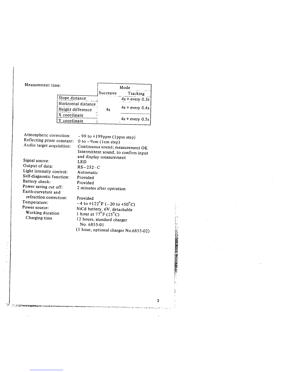
1. Distance measuring....................................................... 2
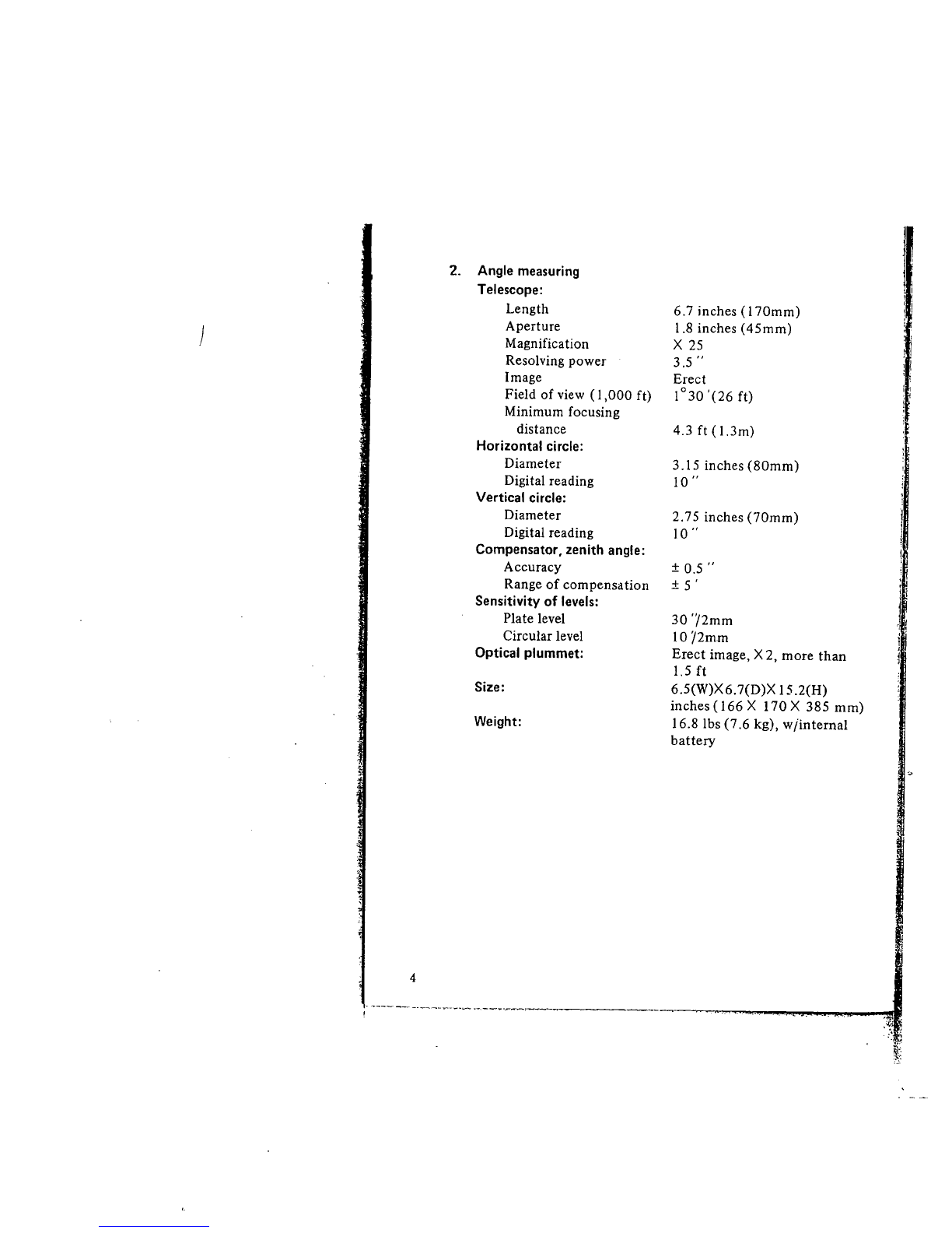
2. Angle measuring. .......................................................... 4
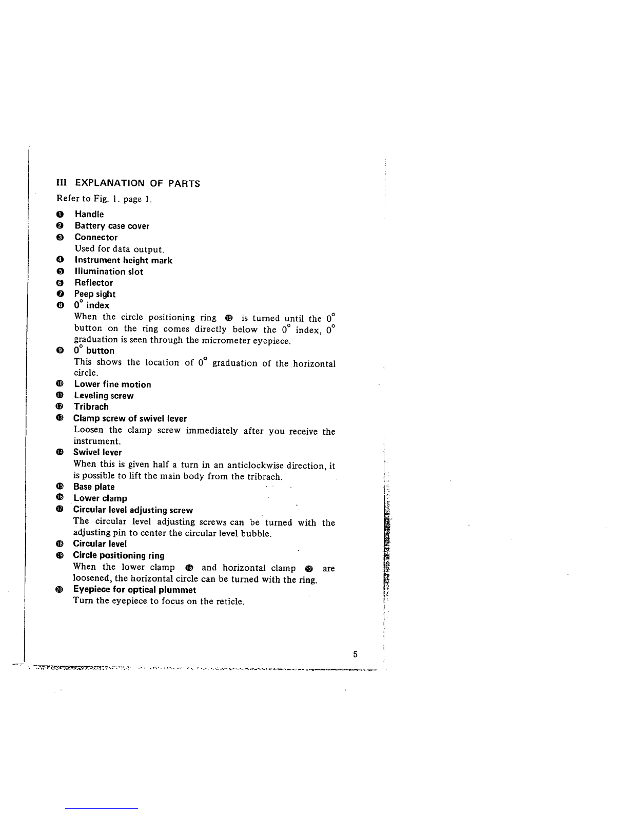
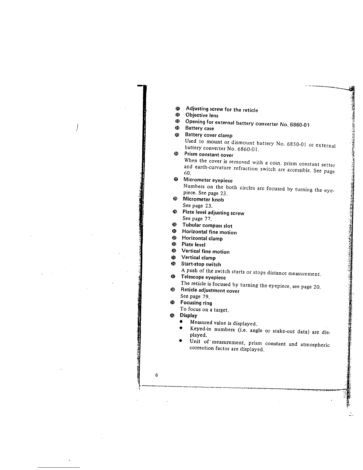
III EXPLANATION OF PARTS .............................................. 5
IV STANDARD SET............................................................. 1 I
\' OPERATION..... .... .... ..... ............................... ........ ........ "17
1. Setting up the SDM3E ............................................ ""..17
. (1) Setting up the tripod................................................. 17
(2) Center the SDM3E by adjusting leg length .................I!!
. (3) Centering with the plumb bob ...................................20
(4) Focusing of the telescope ..........................................20
(5) Sighting'" ............ .................................................... '21
(6) Swivel lever ..............................................................22
2. Measuring angles..... ............................................... ......23
(1) Horizontal and vertical circle reading .........................23
(2) Horizontal angle measurement ...................................25
(3) Zenith angle measurement............................;............2!!
(4) Vertical angle............................................................ 29
3. Distance measurement ..................................................30
(1) Preparation..... ..........................................................30
(2) Measuring the slope distance.....................................33
(3) Keyboard operation ................ ..................... ......... .....34
(4) Mode of measurement ..............................................42
(5) To recall data ..:.........................................................59
VI CORRECTIONS ..................... .............................. ........... '60
1. Prism constant..............................................................60
2. Earth-curvature and refraction correction ......................60
3. Atmospheric correction .................................................61
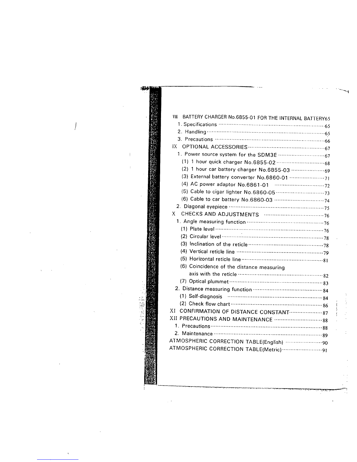
\'I INTERNAL BATTERY No.6850-01...................................63
1. Specifications ...............................................................63
2. Handling' ..................................................................... '63
3. Precautions......................................................... ..........64
~
':~7:~?:", :'.;:;~\7!7~\J'?~:"'.'i".:'..'-:-., =:;-'0 C-:rr'" ..""'e'''. "":"''c':'~ ~,o':-:~;".' ".' ',,, '~'~.o ':~"""~' :
,',' .
\\
._.. . .
. 0 .. .". .
~WiY,;¡(t~:l"'...;.
"-
'.1
r~l
p:
r,\~
fl
((~.
'-'" ...,"",.-.

)
--I
VII BATTERY CHARGER No.6855-01 FOR THE INTERNAL BATTERY65
1. Specifications ................................................................65
2. Handling ................ .... ............. .......................... ........ ....65
3. Precautions................................................................. .66
IX OPTIONAL ACCESSORIES..............................................67
1. Power source system for the SDM3E ............................67
(1) 1 hour quick charger No.6855-02 .............................68
(2) 1 hour car battery charger No.6855-03 ....................69
(3) External battery converter No.6860-01 .....................71
(4) AC power adaptor No.6861-01 ..............................72
(5) Cable to cigar lighter No.6860-05 .............................73
(6) Cable to car battery No.6860-03 ..............................74
2. Diagonal eyepiece .........................................................75
X CHECKS AND ADJUSTMENTS ....................................76
1. Angle measuring function ..............................................76
(1) Plate level................................................................. 76
(2) Circular level.............................................................78
(3) Inclination of the reticle .............................................78
(4) Vertical reticle line ....................................................79
(5) Horizontal reticle line.................................................81
(6) Coincidence of the distance measuring
axis with the reticle ...................................................82
(7) Optical plummet......................... ...... ...... ......... .......... 83
2. Distance measuring function ..........................................84
(1) Self-diagnosis .........................................................84
(2) Check flow chart....................................................... 86
XI CONFIRMATION OF DISTANCE CONSTANT-...................87
XII PRECAUTIONS AND MAINTENANCE .............................88
1. Precautions ................. ............ ............. ....... .................. 88
2. Maintenance........... ........................ .............................. 89
ATMOSPHERIC CORRECTION TABLE(English) ......................90
ATMOSPHERIC CORRECTION TABLE(Metric)........................91
'.~.1~, ~ --~

Fig. 1
I. "';;,~io~ .... . -: 7~. . , ,_. II,. _. ~~~__
~I
~
&- S;~
~J
c"
'.
~.
l':
~~
\,
,
Ii..
~ -,,,
f~'
~
'¡
¡¡
r:-:
,.
t.-
;.
~ ;
;.
i

FEATURES
.Distance and angle measuring functions are synthesized in the i
)SDM3E. Accurate and rapid operation can be executed with I
the SDM3E. i
.Horizontal dist~nce.height difference and coordinate are com- l
¡:
puted and displayed by keying in angle.
.Successive and tracking measurement as well as stake-out can
I
be selected. ¡
.The telescope can be plunged to either direction, enabling the
¡ ,
user to observe both faces, easily. l
.Adjustment of light intensity is not necessa¡y. 'L
.Incoming reflection from prism(s) is confirmed by light value
lamp or buzzing sound.
.All the necessary information is displayed.
.Function to output the measured data is provided.
.Corrections for earth-curvature and refraction are carried out
automatically.
.The SDM3E's power source is cut off two minutes after its last
operation. This saves battery capacity.
.. A convenient handle is provided for easy transportation.
II SPECIFICATIONS
1. Distance measuring
Range: I-prism 35 to 3,900ft ( 10 to l.00m)
3-prism 35 to 5,900ft(JO to I,SOOm)
(under good atmospheric conditions)
:t (5mm + 5ppm 'D)
LED 8-digit
Maximum slope distance
6.561.66ft (1.999.999m)
Successive 0.0 1ft (J mm)
Tracking 0.1 ft (1 Omm)
Standard deviation:
Display:
Minimum count:
2
'--_. .'. .-. ~---,~ ~"---'-"'-""---_._-___-:
:;

e: Mode .-.. -_. ..
Succesive Tracking
.. "'-" '-'_.._, , '-
~!?IJ,e_,!i,stance_, __~ 4s + every 0.3s
. -- -
Horizontal distance: 4s + every O.4s
Height difference 4s
-----.--.- -. "
X coordinate i
Y coordinate I4s + every 0.5s
,
Measurement tim
Atmospheric correction:
Reflecting prism constant:
Audio target acquisition:
Signal source:
Output of data:
Light intensity control:
Self-diagnostic function:
Battery check:
Power saving cut off:
Earth-curvature and
refraction correction:
Temperature:
Power source:
Working duration
Charging time
- 99 to +I99ppm (lppm step)
o to -9cm (Icm step)
Continuous sound; measurement OK
Intermittent sound; to confirm input
and display measurement
LED
RS-232-C
Automatic
Provided
Provided
2 minutes after operation
Provided
-4 to +I22°F (-20 to +50°C)
NiCd battery, 6V, detachable
I hour at nOF (25°C)
12 hours, standard charger
No. 6855-01
(1 hour, optional charger No.6855-02)
:~'T- .~~-~~':r;~,n~~~_,,"'r,..:_""4c:..-~=r""'''::''~..--,,.--....'t_..._...___-._----.'=-'-~______._.._:,_. __ . _.....: :_"'_:~ _'~'."' . ~..
t..
!"
!."
v.;~
~
!".
i.
3

4
. -~--~ - -.--'___i-___..- ._._~_...__,
:'t;
~

II EXPLANATION OF PARTS
Refer to Fig. I. page I.
o Handle
f) Battery case cover
ê Connector
Used for data output.
Ð Instrument height mark
o Illumination slot
o Reflector
Ð Peep sight
e 00 index
When the circle positioning ring æ is turned until the 00
button on the ring comes directly below the 00 index, 00
graduation is seen through the micrometer eyepiece.
o 00 button
This shows the location of 00 graduation of the horizontal
circle.
æ Lower fine motion
CD leveling screw
æ Tribrach
æ Clamp screw of swivel lever
Loosen the clamp screw immediately after you receive the
instrument.
æ Swivel lever
When this is given half a turn in an anticlockwise direction, it
is possible to lift the main body from the tribrach.
æ Base plate
d\ lower clamp
4D Circular level adjusting screw
The circular level adjusting screws can be turned with the
adjusting pin to center the circular level bubble.
Gi Circular level
., Circle positioning ring
When the lower clamp CD and horizontal clamp 0 are
loosened, the horizontal circle can be turned with the ring.
tI Eyepiece for optical plummet
Turn the eyepiece to focus on the reticle.
'. -~~~~~~.~:,?.~-:~:,:,,,.-- .... ......,'\...~, ......_,........_......-...._,.......--~-:~----~
5
I.
f.
"
§

)
a.
ø
ai
tZ
æ
--~;~
:~
-,~
;i
:~I
j:
1(
'~I
'.."1
;
.J
"
j'
il
Adjusting screw for the reticle
Objective lens
Opening for external battery converter No. 6860-01
Battery case
Battery cover clamp
Used to mount or dismount battery No. 6850-01 or external
battery converter No. 6860-0 I.
Prism constant Cover
When the cover is removed with a coin. prism constant setter
and earth-curvature refraction switch are accessible. See page
60.
Micrometer eyepiece
Numbers on the both circles arc focused by turning the eye-
piece. See page 23.
Micrometer knob
See page 23.
Plate level adjusting screw
See page 77.
~ Tubular compass slot
m Horizontal fine motion
G Horizontal clamp
~ Plate level
ai Vertical fine motion
G Vertical clamp
~ Start-stop switch
A push of the switch starts or stops distance measurement.
Telescope eyepiece
The reticle is focused by turning the eyepiece, see page 20.
Reticle adjustment cover
See page 79.
Focusing ring
To focus on a target.
~ Display
· Measured value is displayed.
· Keyed-in numbers (Le. angle or stake-out data) are dis-
played.
· Unit of' measurement, prism constant and atmospheric
correction factor are displayed.
ø
fD
-j
'I
w~
.
~
.~
'Y
- l .
.~;
.4
.r
.~ .
i'
.~ :
. ~ ,
! :
..'5 ;
.;; :
.~ ,
:-; i
f1
m-J !
~
~
. ¡
: ~
6
:.,
~

l.
.¡
~
~-
..
,t
l
Í'
l:
,.
,-;.
l
'"
ír
~
t.
~-.
.r
~:-.
~~~
j'
~.
f
~'
-:~
~ --=\ ~. , ..
Example:
r~'
i
I
- 3 -'~ is displayed when ~ key is pressed.
L'r- L____. atinospheric correction factor; + 45 ppm
i '-.. --, prism constant; - 3cm
unit of measurement; feet
Necessary information is displayed:
.
loooooooolJ : Shows display tunction and microcomputer
1* * * * * * * *1 works normally.
5JJ I 5 TI ; Before slope distance is measured.
HJJ I 5 TI ; Before horizontal distance is measured.
VJJ I 5 TI ; Before height difference is measured.
IX/N JJ I 5 TI : Before X coordinate is measured.
IY/E JJ I 5 TI ; Before Y coordinate is measured.
15-0 ****1 : When the ~key is pressed.
15-0 5; Before slope distance for stake-out is
measured.
15-0 H; Before horizontal distance for stake-out
is measured.
15-0 V: Bl-ore height difference for stake-out is
measured.
15-0 X/N : Before X coordinate for stake-out is
measured.
15-0 Y/E : Before Y coordinate for stake-out is
measured.
IRCL **~ : When the i; key is pressed.
IRCL 5: Before stored slope distance is recalled.
,
IRCL H: Before stored horizontal distance is recalled.
".,~. ": '. . ",-:~i-"~_~.__ ..--,-.-:-~,.._~__.._ "''_'.~'l-...';,:-._r...1-,~~.. __':-_;'~___._~."_",.':,~,_..",,,..
b,
f:
~t
f"'~ '''''\ ,\.
f ..
ï..
i
!'
k
.::
:~t
~
j
¡:
,..
l:
¡
I'
i
7 i

)
I
I
Is-o
I
I I
1- - - - - - - -I
IRCL
IRCL
IRCL
ISI5
IllR T
III R :n
IE 02
IE 0 3
4D Power switch
8
I
X /N J
v
z
y/El
RNGI
RN51
lJ i S TI
H
lJ 0 W NI
LOWI
CON lJl
I~
IJ
: Before stored height difference is recalled.
Before stored X coordiiiate is recalled.
: Before stored Y coordinate is recalled.
: When the ~ key is pressed.
: When the ig key is pressed.
: When the operation to display horizontal,
zenith angle and stake-out data is dis'
continued or finished.
: When no operation was done for more than
10 seconds.
: When no light comes back from the
reflecting prism, before distance measuring.
When the reflected light from the prism was
interrupted for more than 5 seconds.
: When the battery voltage is too low.
: When atmospheric conditions are not suitable
for distance measuring.
: When distance measuring function is
not working properly.
~Ý.',~.. .. ,
l!
)
l.
L
:r
; 1
i ~
, J
¡ i
1 ~l
~ I
.,.)
I
~.,
æ
..
i
~
W:
~
...~
i

ø Keyboard ~~~~~~~~
tI l1 ~ ~ I! ~ l! Ii
0~~~~~~~¡; 0
Fig. 2
Two functions are provided for the keys.
¡. CD To change the sign of keyed-in numbers.
ll . (2) To recall distance data.
GI . CD To key in "5"
~ . (% To measure distance for stake-out.
f' . ú)
~'ø
f'. CD
~'ø
To key in "6".
To measure slope distance.
To key in "7".
To measure horizontal distance.
~. CD To key in "8".
'ø To measure height difference.
~CD To key in "9".
'ø To measure Y coordinate.
~CD To clear keyed-in numbers.
'ø To measure X coordinate.
fC CD To discontinue recallng or keying in data.
~ : ø To discontinue distance measurement.
Q .CD
ll ø No function
To display unit of measurement, prism constant and
atmospheric correction factor.
íD . CD To key in "0".
ll . ø To key in zenith angle.
f' . CD To key in "I".
~ . ø To key in horizontal angle.
.7J.- "':~~'.l:.~;-.;-':-t~"'-;.:.:-'" ;'-',;~..~-. "--............-...~,..---s.....ra__. ..-..-_~.n~...:-_____,~, ..__....-. .._ .. _'_.
~
~
9

)
~ .
'f
i
i
CD
~ :(í
~
¡;
~
~
CD
: (i
CD
, (i
. CD
. (i
. CD
. (i
To key in "2".
To key in stake-out data.
To key in "3".
No function.
To key in "4".
No function.
To key in decimal point.
No function.
No function,
Press the key when keying-in is over.
Q) Audio target acquisition switch
ON and OFF switch for buzzer circuit.
Gl ft/m switch
Switching between feet and meter unit of measurement.
~ Mode switch
Switching between successive and tracking measurement.
4D ppm setter
Obtain atmospheric correction (page 6 I ), and set the value.
4D Light value lamp
The lamp is ON when the light value is adequate.
EE Gun sight
To introduce the target into the field of view.
10
. - - ._.._ -, __'_'___'_"_. n ,_ ...._.___..'_._._._._...__....__._....__~
,,1
,¡
I¡~
~Ê
..~
.k:

IV STANDARD SET
Fig. 3
SDM3E main unit. . . . .
Internal battery
No. 6850-01 ........
Battery charger
No. 6855-01 ........ 1
Illumination package . .. 1
Tubular compass ..... 1
Lens cap . . . . . . . . . .. 1
Lens hood . . . . . . . . " 1
Vinyl cover . . . . . . . .. 1
Tool bag. . . . . . . . . .. 1
Screwdriver. . . . . . . .. i
Lens brush ......... i
Adjusting pin . . . . . . .. 2
Electric light bulb. . . " 1
Silicone cloth. . . . . . .. 1
A tmospheric correction
table ............. 1
Layout . . . . . . . . . . .. i
Operation manual . . . " 1
Carring case . . . . . . .. i
"'~'-.-~-''l.-;----.' ..--._.;....-,-, ..._~--'- -." w'. ,'.. ',. ".- .... -ó'':'-! ".:' :~,.. .-,. . h. ... .'.-.
'i.
't
~
,.
,,~
11

)
Round Out Your Lietz EDM System with these Accessories
ROUND RETRO PRISMS
For use with all EDM systems re-
commending round retro prisms.
Each prism is in a protective con.
tainer which can be quickly detach-
ed from its metal mount. Lietz's
standard prism offset for both
triple and single assem blies is
-30 mm. Triple mount sides are
threaded permitting assembly of
multiple mounts without any
special brackets.
POCKET-SIZE RETRO PRISM
w/tilting mount
No. 7268-32
_!il
~"" '.
SINGLE ROUND TILTING PRISM
MOUNT only
No. 7269-34
12
SIGHTING TARGET FOR RETRO
PRISM
Adjustable height target with 5/8 x.
i i mounting stud. Black anodized
aluminum. *
No. 7270-29 I
TRIPLE PRISM assembly
with mount and sii;hting pole.
(Pole not ilustrated)
No. 7270-31
~ ;r ~
;~' '\
, ." "\
,,'i /'f. '
-, I ~ ..'\ ,-
, .~
SINGLE PRISM assembly
with mount and sighting pole.
(Pole not ilustrated)
No. 7270-32
1t
t.
'------ '-._'--._~ --, '-,_..~ ---~~~~-,-- ,- ---'.._.--~- ._-"-"_._,.~- -.~

TRIPLE MOUNT only
No. 7270-33
SINGLE MOUNT only
No. 7270-34
ROUND PRISM
w/container only (shown in assem.
blies)
No. 7270-35
RETRO PRISM CARRYING
CASES
Vinyl plastic carrying case w/full
zipper for easy access and storage.
Inside padded. Exterior is bright
international orange color. Sizes for
single or triple retro prisms.
No. 7270-51 Triple retro prisms
No. 7270-52 Single retro prisms
."( ~..,., -"';-,, ;-,~,~;-,,-:~,:.,
LIETZ SIGHTING TARGET SET
No. 7311-45 contains one each of
the following:
7269-34 Single Round Tilting
Prism Mount
7270-35 Round Prism w/container
7270-29 Sighting Target for Retro
Prism
7311-38 Tribrach Adaptor w/re-
movable, rotatable center
7311-35 Optical Plummet Tribrach
4.
~...
g
I
..
13

)
I
i
!
TRIBRACHS AND ADAPTORS
OPTICAL PLUMMET TRIBRACH
For precision plumbing. Has circu.
lar level vial with sensitivity of 10
minutes per 2 mm.
Optical plummet focus by push-pull
slide. Range: 1.5 to 50 fi.
No. 7311-35
TRIBRACH LEVELING BASE
Same as above but without optical
plummet.
For use with Azimuth Base
(7150-41).
No. 7311-34
~ _._~--~ _. ~ -.- - ,..., ". ,_._. .~---~-, - --'.- . -- . ,----.--- .- -- --
14
TRIBRACH ADAPTOR
Allows installation of retro prism or
other accessories into tribrach.
5/8 x 11 thread,
No.7311-37
.
TRIBRACH ADAPTOR
Similar to above except with re-
movable, rotatable center.
No. 7311.38 ti
..
i
\
i
, i
~
'~~:

TRAVERSE SET
WITH CARRYING CASE. For
precise triangulation surveys. day or
night.
No. 7312.45 Set contains two each
of the following:
7311.35 Optical Plummet Tribrachs
7311-37 Tribrach adaptors
7312.39 Ilumination units
7312.40 Rotatable sighting targets
mounted on a base
2S
-.~f-
~;J '.
-._ Exploded
view
.
:..~ :~
.~
r=, . .',
.-,.i~...., ". .... .'
...-'... .'"
:~I
LARGE TARGET
Large target 8 'I" x I I *" attaches to
regular target (No. 73 I 2-40) to pro-
vide increased sighting range.
No. 7312-42
RANGE PLUMBING POLE
Aluminum tubing and brass fittings
with hardened steel point. Height
adjusts from 54" to 100". Upper
section mounting stud accepts single
or triple retro prisms; locking disc
prevents prism rotation. Includes
replaceable rod level (No.8071-90).
No. 7270-48
----
TELESCOPING RANGE
PLUMBING POLE
Ideal for EDM and traverse
work. Made of quality alumi-
num tubing with brass fittings
and hardened steel point.
Positive chuck style twist lock
permits height adjustment
from 54" to 100". Replace-
able rod level (No. 807 1-90)
and point (No. 8078-50).
Upper section has 5/8 x i i
mounting stud to accept single
or triple retro prisms.
No. 7270-46
iS

)
TR IPODS
Tripods recommended for use with
these accessories (not included in
price);
No. 7512-52 Wide Frame,
Extension Leg (wood)
No. 7536-75 Wide Frame,
Extension Leg (aluminum)
RANGE POLE SUPPORT
Made with metal center castings,
rustproof steel legs w/one adjustable
(hinged) leg for uneven ground.
No. 8078-90
"...
".,
RANGE POLE TRIPOD
Heavy-duty. Made with metal
center castings. Rustproof steel legs,
adjustable for uneven ground.
No. 8078-95
,
16
POCKET THERMOMETER
Refilabk nlll.11 case. Mercury
filled. Range:-30° to 120°1- in r
increments.
NO.8006-12_:._~
~~
BAROMETER/ AL TIM ETER
with watch-type case.
English-Range 0-15,000 ft.
No. 8001.70
å)
1
,i
7~

V OPERATION
1. Setting up the SDM3E
(I) Setting up the tripod
I) Loosen wing nuts A.
A
Fig. 4
2) Keep tripod closed and raise the tripod head to about chin
leveL. Tighten wing nuts A.
3) Spread the tripod legs so that the three shoes form an
equilateral triangle and the tripod head is positioned
directly over the surveying point.
4) Make sure that: i. the tripod head is approximately
level, 2. the tripod shoes are firmly fixed in the ground.
Fig. 5
If the ground is not solid enough, drive wooden stakes on
which shoes are set.
~¡;l, -." :. .'-. "', . ,. ~ . - ' ,- 17
Table of contents
Other Sokkia Measuring Instrument manuals

Sokkia
Sokkia NET 1200 User manual

Sokkia
Sokkia CX-52 User manual

Sokkia
Sokkia SX series Installation guide

Sokkia
Sokkia SET2CII User manual

Sokkia
Sokkia SRX1 User manual

Sokkia
Sokkia CX-101 User manual

Sokkia
Sokkia im-101 User manual

Sokkia
Sokkia SET 550 Manual instruction

Sokkia
Sokkia DX Series User manual

Sokkia
Sokkia iM-100 Series Installation guide

Sokkia
Sokkia B20 User manual

Sokkia
Sokkia X-1000 series User manual

Sokkia
Sokkia SET630R User manual

Sokkia
Sokkia CX-62 User manual

Sokkia
Sokkia 30R Series User manual

Sokkia
Sokkia 130R Series User manual

Sokkia
Sokkia DT5 User manual

Sokkia
Sokkia iM-50 Series User manual

Sokkia
Sokkia SDL30 User manual

Sokkia
Sokkia CX Series User manual