Solar-Log Smart Relais Station 1x16A User manual

1
Instructions
Solar-Log™ Smart Relais Station
EN

2
Publisher
Solare Datensysteme GmbH
Fuhrmannstr. 9
72351 Geislingen-Binsdorf
Germany
International support
Tel.: +49 (0)7428/4089-300
e-mail: [email protected]
Italy
Technical support: +39 0471 631032
e-mail: [email protected]
France
Technical support: +33 97 7909708
e-mail: [email protected]
Switzerland
Technical support: +41 565 355346
e-mail: switzerland-[email protected]
United States
Technical support: +1 203 702 7189
e-mail: [email protected]

3
Inhaltsverzeichnis
1 Device Description ���������������������������������������������������������������������������������������������4
1.1 Description.......................................................................................................................................................... 4
1.2 Security Advice ................................................................................................................................................... 5
1.3 Content of Delivery ............................................................................................................................................ 5
2 Installation ����������������������������������������������������������������������������������������������������������6
2.1 Start-up the device............................................................................................................................................. 7
2.2 Block Diagram .................................................................................................................................................... 7
2.3 Status LED ........................................................................................................................................................... 8
3 Conguration������������������������������������������������������������������������������������������������������9
3.1 Network design .................................................................................................................................................. 9
3.2 Conguration - IP Address of Solar-Log™ Smart Relay Station .................................................................. 10
3.3 TCP/IP conguration by DHCP........................................................................................................................ 15
4 Operating ����������������������������������������������������������������������������������������������������������16
4.1 Operating the device directly ......................................................................................................................... 16
5 Firmware-Update ���������������������������������������������������������������������������������������������17
5.1 Bootloader Mode ............................................................................................................................................. 17
5.1.1 Activation of the Bootloader Mode.................................................................................................................17
5.1.2 Abandonment of the Bootloader Mode.........................................................................................................18
5.1.3 Factory Reset .....................................................................................................................................................18
6 TechnicalSpecications ����������������������������������������������������������������������������������19
6.1 Optional Sensor................................................................................................................................................ 20

4
Device Description
1 Device Description
1�1 Description
The Solar-Log™ Smart Relais Station 3 x 16A / 1 x 16A is a multipurpose device that is suitable for switching and
monitoring of voltages. It has the following features:
• Suitable for top hat rail mounting.
• Solar-Log™ Smart Relais Station 1 x 16A: 1 switchable, potential-free relay output with 230V (AC 16A) swit-
ching voltage.
• Solar-Log™ Smart Relais Station 3 x 16A: 3 switchable, potential-free relay outputs with 230V (AC 16A) swit-
ching voltage.
• The measurement of Power, Voltage and Temperature (with optional sensor) is shown in section Diagnostics |
Smart Energy | Status (current).
• Legible LED display visualizes Total Current, IP Address, Sensor Values and Error Messages.
• All circuit outputs can be switched individually on the device. The automatic control of the Solar-Log™ takes
precedence over the manual operation of the Solar-Log™.
• Simultaneous switching of multiple outputs is prevented by automatic latency of 1 second.
• States of the relay outputs are displayed with bicolored LEDs on the front page.
• Connection for an external sensor.
• Possible firmware update in operation via Ethernet.
• Low own consumption.
• Developed and produced in Germany.
Solar-Log™ Smart Relais Station 3x3,5kW and 1x3,5kW

5
Device Description
1�2 SecurityAdvice
• The device must be installed only by qualified personnel according to the following installation and operating
instructions.
• The manufacturer does not accept responsibility in case of improper use of the device and particularly any
use of equipment that may cause personal injury or material damage.
• The device contains no user-maintenable parts. All maintenance has to be performed by factory trained ser-
vice personnel.
• The device may only be connected by a low voltage power supply (12V - 24V AC or DC) .
• The device is intended for indoor use only. Do NOT install them in an area where excessive moisture or heat is
present.
• Because of safety and approval issues it is not allowed to modify the device without our permission.
• Please note the safety advises and manuals of connected devices, too.
• The device is NOT a toy. It has to be used or stored out or range of children.
• Care about packaging material. Plastics has to be stored out of range of children. Please recycle the packaging
materials.
• In case of further questions, about installation, operation or usage of the device, which are not clear after
reading the manual, please do not hesitate to ask our support team.
1�3 ContentofDelivery
The package includes:
• Solar-Log™ Smart Relais Station 3 x 16A / 1 x 16A
• Din rail power supply
Input 110-240 VAC 0,88 A
Output 12VDC 1,25 A
• DC connector cable LiY-Z 2x0,75 sw/rt with ferrule, L=10 cm
• CD-ROM and manual

6
Installation
2 Installation
Number Description
1 Power supply (12V-24V AC oder DC).
2 Stop input for shutdown of all relays.
3 Solar-Log™ Smart Relais Station 1 x 16A: 1 relay output.
Solar-Log™ Smart Relais Station 3 x 16A: 3 relay outputs.
4 L1 - L3 indicator LED display.
5 LED display for load or sensor display.
6 3 indicator LEDs for relay outputs.
7 Status LED.
8 Button for OK, Select or bootloader mode.
9 Network connector RJ45.
10 Connector for sensor.
11 Neutral wire connection for measurement electronics.
12 Solar-Log™ Smart Relais Station 1 x 16A: 1 relay input.
Solar-Log™ Smart Relais Station 3 x 16A: 3 relay inputs.

7
Installation
2�1 Start-upthedevice
• Connect the device to an AC Adaptor (12V-24V AC or DC).
• Plug the network cable into the Ethernet socket (RJ45).
• Connect the neutral wire to the neutral wire connector (11).
• Connect the relay outputs to the loads that should be used.
• Connect the relay inputs with the corresponding phase.
• Attach a switch (if any) to the stop input.
• Connect the sensor (if any) to the device.
2�2 BlockDiagram
L1
L1
N
N
LAN Sensor / RS232
N
A
V
Power supply
AC or DC
12-24 V, 0.3 A
12 - 24 V
≂
Stop
Smart Relais Station
1 x 16A (1 x 3,5 kW)
18 19 20
1 2 3 4 5 6 7 89 10 12 13 14 15 16 17
21 22 23 24 25 26 27 28 29
11
30 31 32 33 34 35
Block diagram for the Solar-Log™ Smart Relais Station 1 x 16A
Neutral line has to
be connected for
metering electro-
nics.

8
Installation
L1 L2 L3
L1 L2 L3
N
N
LAN Sensor / RS232
NAA A
V
Power supply
AC or DC
12-24 V, 0.3 A
12 - 24 V
≂Stop
Smart Relais Station
3 x 16A (3 x 3,5 kW)
V
V
18 19 20
1 2 3 4 5 6 7 89 10 12 13 14 15 16 17
21 22 23 24 25 26 27 28 29
11
30 31 32 33 34 35
Block diagram for the Solar-Log™ Smart Relais Station 3 x 16A
2�3 StatusLED
The Status LED shows different states of the device:
• Red: Device is not connected to the Ethernet.
• Orange: Device is connected to the Ethernet, TCP/IP settings are not allocated.
• Green: Device is connected to the Ethernet, TCP/IP settings allocated.
• Periodic blinking: Device is in Bootloader mode.
Neutral line has to
be connected for
metering electro-
nics.

9
Configuration
3 Conguration
3�1 Networkdesign
The Solar-Log™ Smart Relay Station must be in the same local area network as the Solar-Log™.
View of network topology
10
Configuration
3�2 Conguration-IPAddressofSolar-Log™SmartRelayStation
The Solar-Log™ Smart Relay Station is equipped with a standard Ethernet RJ45 network socket that can be connec-
ted with any commercially available network cable.
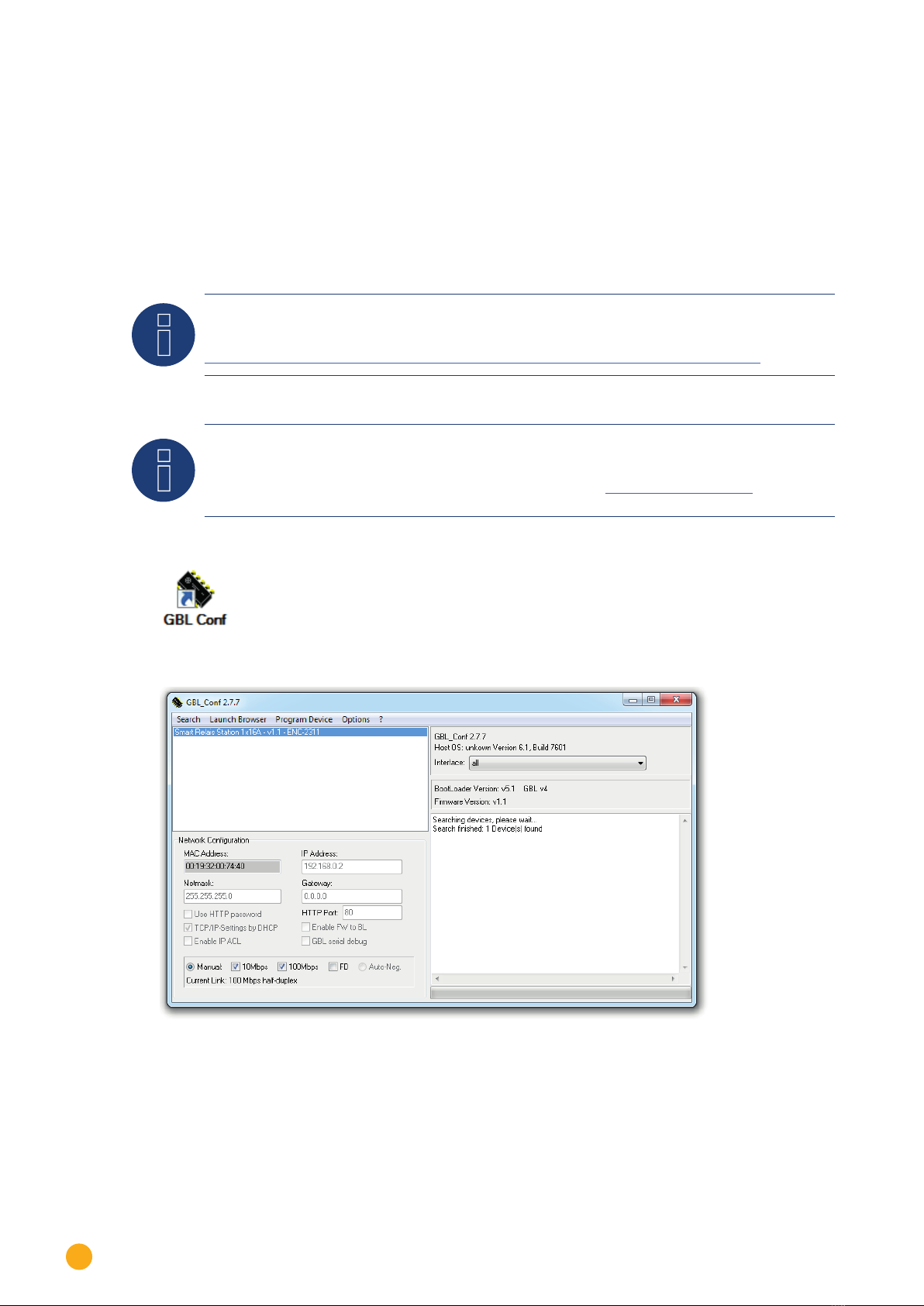
Procedure
• The commissioning steps must be completed.
• Download and install the Gude System Tool (GBL_Conf.exe).
Note
The program as well as the rmware le can be found under:
https://www.gude.info/en/monitoring-remote-io/remote-io/expert-net-control-2312-1.html
Note
In the manual you will nd the screenshots of GBL_Conf 2.7.7. The latest GBL_Conf is 2.7.11 and has
additionally the port HTTPS in the conguration. (See also GUDE „Expert Net Control 2312“ user ma-
nual)
• Start up the system tool.
• The software automatically searches for the Solar-Log™ Smart Relay Stations within the local area network.
• The devices found are listed in the software.
• Activate the Boot Loader mode of the Solar-Log™ Smart Relay Station:
Hold both buttons pressed down for 3 seconds. At first „blr“ is displayed. After 3 seconds the display changes
to „bld“. Further information about the Boot Loader Mode can be found in chapter 5.1.
• Go back to the system tool GBL_Conf

11
Configuration
Note
The Solar-Log™ Smart Relay Station has the IP address 192.168.0.2 as factory setting.
• In the Search menu, select the item Boot Loader Mode Devices only. In this mode, the IP address and netmask
(subnet Mask) fields can be edited.
• Set the IP address and the netmask (subnet mask) accordingly to the used network and deactivate the functi-
on TCP/IP Setting by DHCP.
• Save the settings on the device by means of the menu item Program Device using the Save Config function.
• The network settings of the Solar-Log™ Smart Relay Station have been adjusted.
• Die Netzwerkeisntellungen der Solar-Log™ Smart Relais Station wurden angepasst.
• Exit the Boot Loader mode. Hold both buttons of the Solar-Log™ Smart Relay Station down for 3 seconds.
„bld“ disappears from the display.
In the GBL_Conf system tool select the item All Devices in the Search menu. The set IP address and netmask (sub-
net mask) are displayed under Network Configuration. The fields are gray-shaded and cannot be changed here.
System tool GBL_Conf after successful IP address conguration
12
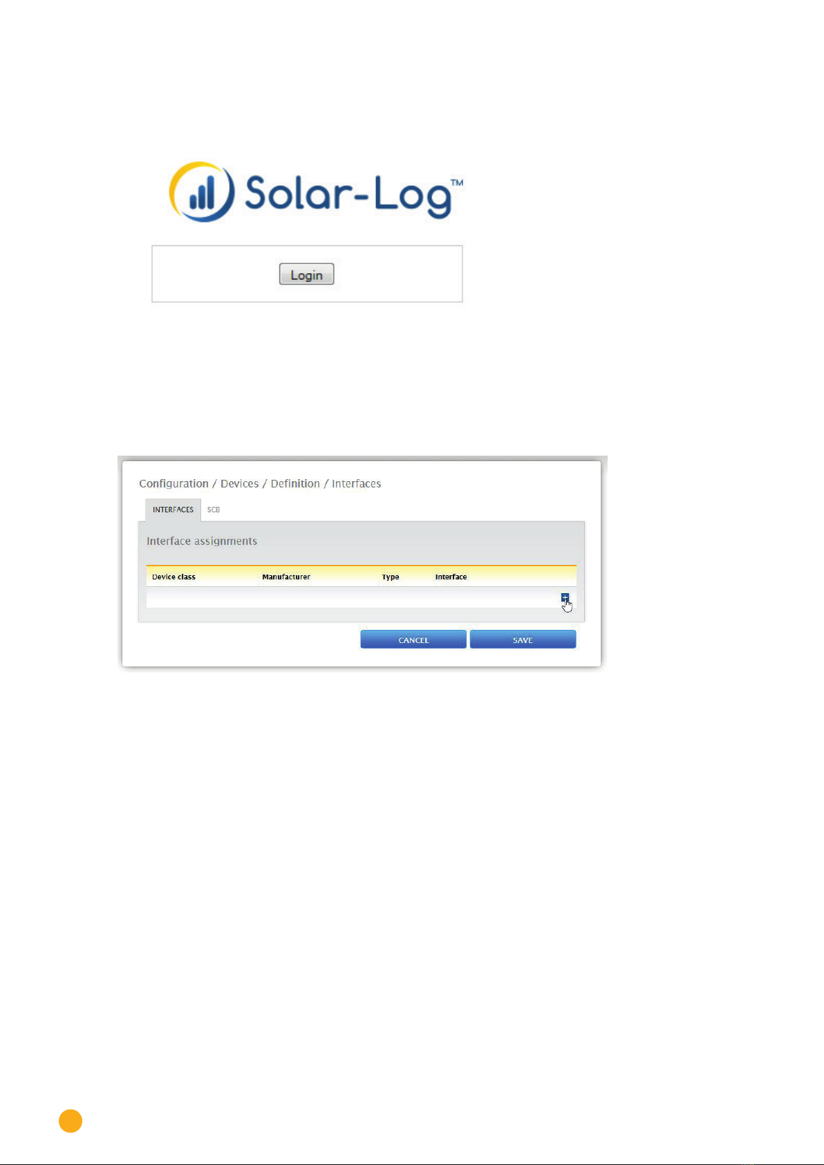
Configuration
• The browser is opened by means of a double click on the blue colored line and the Start-screen of the So-
lar-Log™ Smart Relay Station is displayed.
Start-screen of the Solar-Log™ Smart Relay Station
• The IP configuration of the Solar-Log™ Smart Relay Station has been successfully concluded.
• Go to the web menu of the Solar-Log™.
• Navigate to the item Configuration | Devices | Definition | Interfaces.
• The following menu is displayed:

13
Configuration
Select the Relay Station with the plus symbol. The following settings are required here (see the figure further
below):
Device class:
• Switch
Manufacturer:
• Solar-Log
Type:
• Smart Relay Station 3x 3.5kW (or 1x 3.5kW)
Interface:
• Ethernet
Number of devices:
• 1 in the example
Confirm the settings with OK. Then start the device detection from the Configuration | Devices | Detection
menu.
To enter the IP assigned above, go to the Configuration | Devices | Configuration menu under Device Configura-
tion, select the device and enter the IP address in the corresponding box.
Adjust the remaining configuration settings in this section (see the example figure further below).


15
Configuration
3�3 TCP/IPcongurationbyDHCP
After switching on the device is scanning on the Ethernet for a DHCP server and requests an unused IP address.
Check the IP address that has been assigned and adjust if necessary, that the same IP address is used at each
restart. To turn off DHCP use the software GBL_Conf.exe or use the configuration via the web interface.
To check the network settings with GBL_Conf.exe, start the program and choose „All Devices“ in the „Search“
menu. From the list select the appropriate device. The lower part of the left half of the window now shows the
current network settings of the device. If the IP address is displayed with the default settings (192.168.0.2), either
no DHCP server is present on the network, or there could be no free IP address assigned to it.

16
Operating
4 Operating
4�1 Operatingthedevicedirectly
The current status of the output is indicated by the color of the LED. Red indicates that the output is off, green
shows that the output is on. On the device are the buttons „select“ and „ok“. If you press „select“, the LED will blink
for the first output, ie the output is selected. Press „select“ again to select the next output. Hold down the button
„ok“ for two seconds, then the status of the selected output is toggled.

17
Firmware-Update
5 Firmware-Update
To perform a firmware update, the program GBL_Conf.exe and the latest firmware is needed.
• Enable the bootloader mode (see Chapter Bootloader Mode).
• Start GBL_Conf.exe.
• Select the device for which a firmware update is to be performed.
• Click „Program Device“ and then select there „Firmware Update“.
• Specify the firmware file that should be uploaded.
Upon completion of the update process, please start the new firmware of the device. You can do this by simply
leaving the bootloader mode.
A firmware update, unlike other functions, is not sent as a network broadcast. Therefore, the device must have a
valid IP address and a valid netmask before the firmware update. If necessary, please correct the entries in GBL_
Conf.exe in bootloader mode and save them with „Save Config“.
If after a firmware update, the web page is not displayed correctly anymore, this may be related to the interaction
of Javascript with an outdated browser cache. Not always helps a Ctrl-F5, it is recommended that you manually
delete the cache in the browser options. Alternatively, you can test start the browser in „private mode“.
5�1 Bootloader Mode
Certain actions can, for safety reasons, only be carried out if the device is in bootloader mode. The following ope-
rations are possible only in Bootloader Mode:
• Firmware Update.
• Configuration with GBL_Conf.exe.
• Factory Reset.
5�1�1 ActivationoftheBootloaderMode
Via push button
• Hold both buttons for 3 seconds (only if the device has 2 buttons).
or
• Remove the power supply.
• Hold down the button (or the „Select“ button for devices with 2 buttons). If the push button is recessed, use a
pin or paper clip.
• Connect the operating voltage.
By Software: (only if „Enable FW to BL“ was previously activated in GBL_Conf.exe)
• Start GBL_Conf.exe.
• Do a network search with the „Search“ menu action.
• Activate in menu „Program Device“ the item „Enter Bootloader“.

18
Firmware-Update
Whether the device is in bootloader mode, is indicated by the flashing of the status LED, or it is shown in GBL_
Conf.exe, after a renewed device search, with the appendix „BOOT-LDR“ after the device name. In bootloader
mode the program GBL_Conf.exe can disable the password and the IP ACL, perform a firmware update, and resto-
re the factory settings.
Note
Activation of the bootloader mode and an abandonment of the bootloader does not change the state
of the power or output ports as long as the supply voltage is maintained.
5�1�2 AbandonmentoftheBootloaderMode
Via push button
• Hold both buttons for 3 seconds (only if the device has 2 buttons).
or
• Remove and connect the power supply without operating a button.
By Software
• Start GBL_Conf.exe.
• Do a network search with the „Search“ menu action.
• In menu „Program Device“ activate the item „Enter Firmware“.
5�1�3 FactoryReset
If the device is in bootloader mode, it can always be put back to its factory default. All TCP / IP settings are reset in
this operation.
Via push button
• Activate the Bootloader Mode of the device.
• Hold down the button (or the „Select“ button for devices with 2 buttons) for 6 seconds. If the push button is
recessed, use a pin or paper clip.
• The status LED will blink in a fast rhythm, please wait until the LED blinks slowly (about 5 seconds).
By Software
• Activate the Bootloader Mode of the device.
• Start GBL_Conf.exe.
• In menu „Program Device“ activate the item „Reset to Fab Settings“.
• The status LED will blink in a fast rhythm, please wait until the LED blinks slowly (about 5 seconds).

19
Technical Specifications
6 TechnicalSpecications
Interfaces 1 x Ethernet port (RJ45)
Solar-Log™ Smart Relais Station 1 x 16A: 2 x screw terminal with 1 x relay
make contact (230V AC 16A)
Solar-Log™ Smart Relais Station 3 x 16A: 6 x screw terminal with 3 x relay
make contacts (230V AC 16A)
2 x screw terminal for power supply
2 x screw terminal with 1 x stop input
2 x screw terminal for neutral wire
1 x Mini-DIN socket for external sensor
Network connectivity 10/100 MBit/s 10baseT Ethernet
Protocols TCP/IP, HTTP, DHCP, ICMP, SNMP v1/v2c + traps, Syslog, SMTP
Power Supply 12V to 24V AC or DC, 0.3 A
Environment
Operating temperature
Storage temperature
Humidity
0°C to 50°C
-15°C to 60°C
10% to 85%
Case Plastics black
Measurements 105mm x 70mm x 90mm (L x H x T)
Weight approx. 280g
Note
Due to design, only alternating currents can be measured, no direct currents.

20
Technical Specifications
6�1 Optional Sensor
An external sensor can be connected to the Solar-Log™ Smart Relais Station 1 x 16A / 3 x 16A. The following
sensors are currently available.
Temperature-Sensor 7001
Cable length ~ 2m
Connector Mini-DIN
Measurement range -20°C to +80°C at ±2°C (maximum) and ±1°C (typical)
Humidity/Temperature-Sensor 7002
Cable length ~ 2m
Connector Mini-DIN
Measurement range Temp: -20 to +80°C, ±0,5°C (maximum) and ±0,3°C (typical)
Humidity: 0-100%, ±3% (maximum) and ±2% (typical)
This manual suits for next models
1
Table of contents
Popular Relay manuals by other brands


Broyce Control
Broyce Control ELR01PN quick guide

Siemens
Siemens SIRIUS 3TK2820 Original operating instructions

ABB
ABB CM Series Operating and installation instructions

SEA Praha
SEA Praha GSM-R5-DINW user manual

CTM LYNG
CTM LYNG Mkomfy R-T 25A Installation instructions user instructions

Pilz
Pilz PNOZ c2 operating manual


