Broyce Control Ltd., Pool Street, Wolverhampton, West Midlands WV2 4HN. ngland
Tel: +44 (0) 1902 773746 Fax: +44 (0) 1902 420639 mail: sales@broycecontrol.com Web: www.broycecontrol.com
The Information provided in this literature is believed to be accurate (subject to change without prior notice); however, use of such information shall be entirely at the user’s own risk
LR01PN_30PN-1-A.DOCX
Page 3 of 3
1811
•
DIMENSIONS
63.5mm
45mm
61mm
85mm
49.5mm
44mm
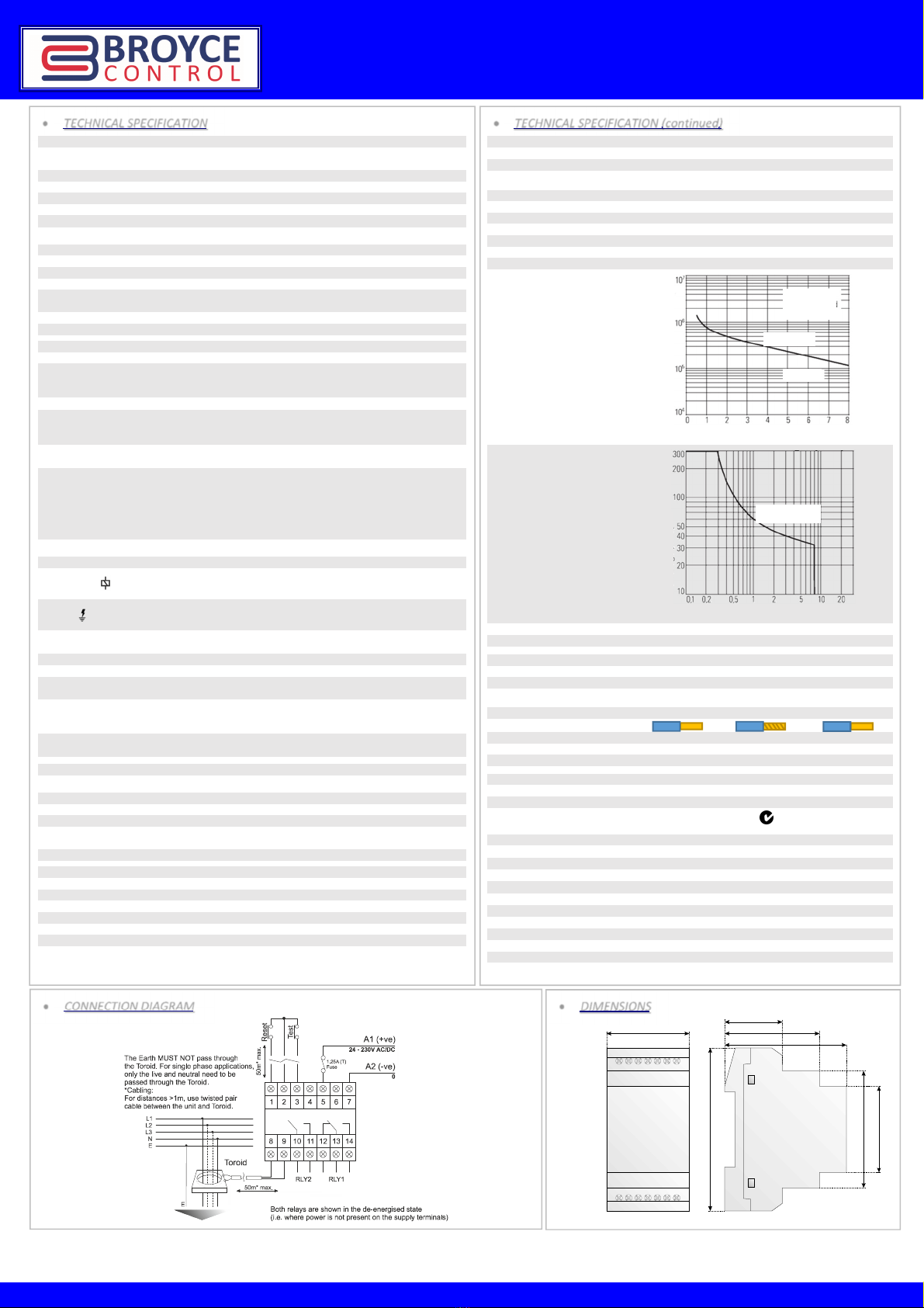
•
CONNECTION DIAGRAM
•
TECHNICAL SPECIFICATION (continued)
Tem erature rating
Operating: -20 to +60°C
Storage: -30 to +70°C
Relative humidity: +95% max.
Out ut
RLY1 RLY2
Terminals: 12, 13, 14 10, 11
Contact arrangement: 1 x SPDT 1 x SPNO
AC1 (250V) 8A (2000VA) 8A (2000VA)
AC15 (250V) 2.5A 2.5A
DC1 (25V) 8A (200W) 8A (200W)
lectrical life:
Switching current (A)
DC load capacity:
DC current (A)
Dielectric voltage: 2kV AC (rms) I C 60947-1
Rated impulse withstand voltage: 4kV (1.2/50µS) I C 60664
Housing
Material: Grey flame retardant Lexan UL94 V0
Weight: 120g
Mounting option: On to 35mm symmetric DIN rail to BS N 60715
Terminal conductor size
Cable type:
Nominal cross section: 0.2 – 4mm
0.2 – 2.5mm
0.2 – 2.5mm
30 – 12AWG 30 – 12AWG 30 – 12AWG
Stripping length: 6mm
Standards
Product: I C 60947-2 / Annex M, I C 60755, I C 62020
MC: I C 61543, I C 61000-4 Series, CISPR 22
C and RoHS Compliant. C-tick
Toroid o tions
Part number: Aperture Internal diameter/size: I∆n (min.) A
BZCT035 35mm ∅ 0.006
BZCT050 50mm ∅ 0.006
BZCT070 70mm ∅ 0.03
BZCT120 120mm ∅ 0.1
BZCT160 160mm ∅ 0.1
BZCT210 210mm ∅ 0.3
BZCTR305
115 x 305mm 0.3
BZCTR350
150 x 350mm 0.3
BZCTR470
160 x 470mm 0.3
•
TECHNICAL SPECIFICATION
Auxiliary Power Su ly (5, 7)
Voltage range (Us): 24 – 230V AC/DC
1 25A (T) rated fuse should be installed in line with terminal 5 (A1)
Frequency range (AC supply): 50/60Hz
Supply variation: 85 – 115% of Us
Auxiliary supply is galvanically isolated from the Toroid and Remote Test/Reset connections
Overvoltage category: III (I C 60664)
Rated impulse withstand voltage: 4kV (1.2/50µS) I C 60664
Power consumption (max.): AC: 6VA, DC: 5W
Monitored in ut (via external Toroid connected to terminals 8 and 9)
Unit classification: Type A
Measurement principle: True R.M.S.
Input DSP filter cut-off 150, 300 or 450Hz (factory default = 150Hz)
xternal Toroid ratio: Selectable between 600:1 and 1000:1 in 100:1 steps (factory default
= 1000:1)
Monitored leakage current range: ELR01PN ELR30PN
1.5mA – 1A 7.5mA – 30A
User adjustments
ELR01PN ELR30PN
Trip level settings (I∆n):
6mA, 10mA, 30mA, 50mA,
100mA, 200mA, 300mA,
500mA, 750mA, 1A
30mA, 100mA, 300mA, 500mA, 1A,
3A, 5A, 10A, 20A, 30A
Actual trip level: 85% of I∆n (+/- 5%)
Rated residual non-operating
current (I∆no): <80% of I∆n
Reset level: ≈ 85% tripped level
Time delay (Non-operate) settings
(∆t):
0
, 60ms, 150ms, 250ms, 500ms, 800ms, 1s, 2.5s, 5s, 10s
1
actual delay when set to 0 (instantaneous) is <25ms @ 5 x I
∆
n
Note:
1.
For I∆n of 30mA or less (model dependant) the Time delay is fixed to 0 (instantaneous) and is not adjustable
(i.e. any other delay cannot be set)
2.
The unit is factory set to 30mA (or 6mA) (and instantaneous delay). Adjustment of these settings can be
made if necessary to suit the requirements of the installation. To prevent tampering of the settings, the clear
window can be secured in place using a 2mm or 2.5mm wide cable tie (not supplied).
Reset time: <1s (from supply interruption)
LED indication
Power Supply Green x1
LED is usually permanentl
y lit but will flash if no valid
profile has been selected or there was a communication
error with the smartphone
Tripped Red x 1
time out (i e before tripping) or
external toroid is disconnected LED will also flash prior to
unit reclosing if “auto-reclosure” mode enabled
Bargraph (25, 50, 75%) Yellow x3
Test and Reset
Front ush button Remote N.O. ush button(s)
“Test” method (assuming unit is
in the non-tripped state)
Press once to trip the
unit
Press “Test” button to trip the unit
(connected to terminals 2 and 3)
“Reset” method (assuming unit is
in the tripped state and fault
current cleared)
Press once to reset
the unit
Press “Reset” button to reset the unit
(connected to terminals 1 and 2)
Minimum trigger time: >∆t >80ms + ∆t setting
(only applicable to remote “Test”)
Auto-reset
To enable: Via app (or place wire link between terminals 1 and 2)
Auto-reclosure
To enable and adjust parameters: Via app only
Reclosure attempts: Selectable between 1 and 10 (factory default = 6)
Time between reclosure attempts
(t
r
):
t
r
after first attempt which doubles after each attempt i.e. 2t
r
, 4 t
r
, 8
t
r
, etc. Options are: 1, 2.5, 5, 7.5 and 10s (factory default = 7 5s)
Timeout: Selectable between 1 and 20mins (factory default = 15mins)
Relay o erational modes
To change modes: Via app only
RLY1 RLY2
Key (assuming non-tripped state): S.O. (factory default) P.S.O. (factory default)
S.O. = Standard Output S.O. Pre-alarm*
(relay normally de-energised) P.S.O. P.S.O.
P.S.O = Positive Safety Output S.O. S.O.
(relay normally energised) * Relay energises when Pre-alarm threshold exceeded (factory
default = 50% of I
∆
n) Threshold can be changed via app
Resistive
250V AC
Earth Leakage Relay – Ty e A (with NFC Technology)