Solar Stik PRO-VERTER Installation instructions

|1
January 2020 |Solar Stik®, Inc.
OPERATOR AND MAINTENANCE
MANUAL FOR
PRO-VERTER REMOTE
MONITORING KIT LAN
SS P/N(s) 20-0702602
Version 1.0
Updated:20200106
DISTRIBUTION STATEMENT A. Approved for public release; distribution is unlimited.

Operator and Maintenance Manual for PRO-Verter RMK LAN
January 2020 |Solar Stik®, Inc.
2 |
Contents
GENERAL INFORMATION, EQUIPMENT DESCRIPTION, AND THEORY OF OPERATION
Introduction . . . . . . . . . . . . . . . . . . . . . . . . . . . . . . . . . . . . . . . . . . . . . . . . . . . . . 4
Installing the RMK . . . . . . . . . . . . . . . . . . . . . . . . . . . . . . . . . . . . . . . . . . . . . . . . . . 4
Connecting a PC Directly to the RMK . . . . . . . . . . . . . . . . . . . . . . . . . . . . . . . . . . . . . . . 6
OPERATOR INSTRUCTIONS
Viewing the System Data . . . . . . . . . . . . . . . . . . . . . . . . . . . . . . . . . . . . . . . . . . . . . . 7
Current Settings Page . . . . . . . . . . . . . . . . . . . . . . . . . . . . . . . . . . . . . . . . . . . . . . .7
Current Conditions Page (left side of screen) . . . . . . . . . . . . . . . . . . . . . . . . . . . . . . . . . . . 8
Current Conditions Page (right side of screen) . . . . . . . . . . . . . . . . . . . . . . . . . . . . . . . . . . 9
Historical Data Page. . . . . . . . . . . . . . . . . . . . . . . . . . . . . . . . . . . . . . . . . . . . . . . 10
Fault Codes and Inverter Status Codes . . . . . . . . . . . . . . . . . . . . . . . . . . . . . . . . . . . . . 11
Setting a PC Static IP Address . . . . . . . . . . . . . . . . . . . . . . . . . . . . . . . . . . . . . . . . . . 12
Connecting the RMK to a Network via a Router . . . . . . . . . . . . . . . . . . . . . . . . . . . . . . . . 15
Files on the USB Drive Included with the System . . . . . . . . . . . . . . . . . . . . . . . . . . . . . . . . 15
Editing the Interfaces File . . . . . . . . . . . . . . . . . . . . . . . . . . . . . . . . . . . . . . . . . . . . 16
Updating the Interfaces File in the RMK . . . . . . . . . . . . . . . . . . . . . . . . . . . . . . . . . . . . . 17
TROUBLESHOOTING PROCEDURES
Using the LED Indicators to Determine the RMK’s Status . . . . . . . . . . . . . . . . . . . . . . . . . . . 18
Common Problems During Startup . . . . . . . . . . . . . . . . . . . . . . . . . . . . . . . . . . . . . . . 19
Operating the PRO-Verter without the RMK . . . . . . . . . . . . . . . . . . . . . . . . . . . . . . . . . . 19
RMK LAN Troubleshooting and Repair . . . . . . . . . . . . . . . . . . . . . . . . . . . . . . . . . . . . . 20
ABOUT SOLAR STIK, INC.
Contact . . . . . . . . . . . . . . . . . . . . . . . . . . . . . . . . . . . . . . . . . . . . . . . . . . . . . . . 27
List of Tables
Table 1. Inverter Fault and Status Codes ....................................................................................................................... 11
Table 2. RMK LED Indicator Guide................................................................................................................................. 18
Table 3. Link and Activity LED Meanings ....................................................................................................................... 18

|3
January 2020 |Solar Stik®, Inc.
Operator and Maintenance Manual for PRO-Verter RMK LAN
Section Page(s) Description Date
Published 2016
20–26 Added: RMK LAN Troubleshooting and Repair 20180209
Setting a PC Static IP Address 12–14 Updated instructions for Windows 10 20190402
Revision History
List of Figures
Figure 1. Solar Stik PRO-Verter RMK ............................................................................................................................... 4
Figure 2. The RMK installed on the PRO-Verter Faceplate .............................................................................................. 4
Figure 4. Correct (left) and incorrect (right) routing and securing of cables ..................................................................... 5
Figure 3. The RMK Ports ................................................................................................................................................. 5
Figure 6. RMK connected to PC...................................................................................................................................... 6
Figure 5. Connecting an Expander Pak and the PRO-Verter .......................................................................................... 6
Figure 7. Home Screen and Current Settings of the RMK graphical user interface......................................................... 7
Figure 8. Current Conditions Page (left side).................................................................................................................... 8
Figure 9. Current Conditions Page (right side) ................................................................................................................. 9
Figure 10. Historical Data Page...................................................................................................................................... 10
Figure 11. “Control panel” search .................................................................................................................................. 12
Figure 12. Control Panel window.................................................................................................................................... 13
Figure 13. Network and Internet window ....................................................................................................................... 13
Figure 14. Network and Sharing Center window............................................................................................................ 13
Figure 15. Ethernet Status and Ethernet Properties windows ....................................................................................... 14
Figure 16. Internet Protocol Version 4 Properties window ............................................................................................. 14
Figure 17. List of les on the USB drive ......................................................................................................................... 15
Figure 18. Interfaces le ................................................................................................................................................. 16
Figure 19. Updating the RMK’s interfaces le ................................................................................................................ 17
Figure 20. Functions of LEDs below the Ethernet port .................................................................................................. 18
Figure 21. RJ11 Crossover wire connecting the REMOTE and INVERTER ports .......................................................... 19
Figure 22. RMK on PRO-Verter Faceplate...................................................................................................................... 20
Figure 23. Fastener and status LED locations................................................................................................................ 20
Figure 24. Removing RMK fasteners.............................................................................................................................. 20
Figure 25. Removing control board ................................................................................................................................ 21
Figure 26. Locations of coin cell battery and fuse on control board.............................................................................. 21
Figure 27. Removing coin cell battery ............................................................................................................................ 21
Figure 28. Testing coin cell battery voltages .................................................................................................................. 21
Figure 29. Two-amp blade fuse ...................................................................................................................................... 22
Figure 30. Fuse removal/replacement ............................................................................................................................ 22
Figure 31. Testing good fuse with a multimeter.............................................................................................................. 22
Figure 32. Reading for a blown fuse............................................................................................................................... 22
Figure 33. Removing the microSD card from the control board..................................................................................... 23
Figure 34. Disk imager user interface............................................................................................................................. 23
Figure 35. Creating the target image .............................................................................................................................. 24
Figure 36. Read results for a damaged microSD card ................................................................................................... 24
Figure 37. Read results for an undamaged microSD card ............................................................................................. 24
Figure 38. Reinstalling control board.............................................................................................................................. 25
Figure 39. Reinstalling fasteners .................................................................................................................................... 25
Operator and Maintenance Manual for PRO-Verter RMK LAN
January 2020 |Solar Stik®, Inc.
4 |
GENERAL INFORMATION, EQUIPMENT DESCRIPTION,
AND THEORY OF OPERATION
Introduction
The Remote Monitoring Kit (RMK) provides remote access to vital operating data of a Hybrid Power
System (HPS) via the user interface on the PRO-Verter Faceplate. The RMK also records and stores
all of the data from the PRO-Verter and provides tabular and graphical reports of these data in a
browser-based user interface.
Figure 1. Solar Stik PRO-Verter RMK
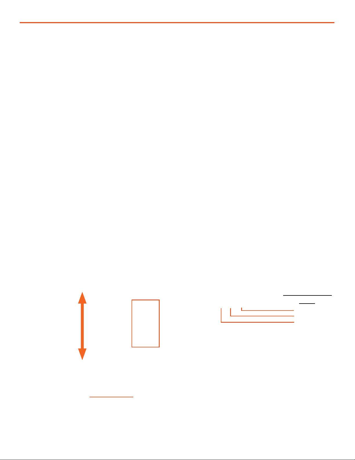
Installing the RMK
1. Install the RMK to the PRO-Verter Faceplate in the designated space using the four (4) fasteners
provided. The RMK can be installed in two different orientations. Installing it with the USB ports
facing the front of the case and the power port toward the back makes access to the USB ports
easier. See subsequent steps.
USB Ports
Power
Port
Figure 2. The RMK installed on the PRO-Verter Faceplate
Preferred mounting
orientation for the
RMK
REMOTE
ETHERNET
INVERTER
24V DC 5
A POWER
TERMINALS
RMK Faceplate
ports
|5
January 2020 |Solar Stik®, Inc.
Operator and Maintenance Manual for PRO-Verter RMK LAN
2. Connect RMK to the PRO-Verter: Two RJ11 crossover wires are included with the RMK: one
connects the “Inverter” ports, and the other connects the “Remote” ports (Figure 2). The red or
black 3’ Cat5 straight-through cable connects the “Ethernet” ports. The power cable plugs into
the “Power” port on the back side of the RMK, and the other end of this wire is connected to the
24 V, 5 A DC terminals on the front left-hand corner of the Faceplate. Note: Red to red, black to
black.
RJ11 Crossover Cable
To Inverter Port
RJ11 Crossover Cable
To Remote Port
24VDC Power Port
CAT5 straight-
through cable
connects
ETHERNET
ports
Figure 3. The RMK Ports
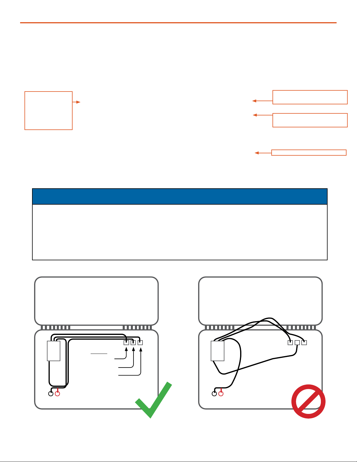
NOTICE
The cables connecting the RMK to the PRO-Verter must be bundled together and secured
to the Faceplate to prevent them from slipping between the lid and the body of the PRO-
Verter and causing damage to the cables and/or the PRO-Verter case hinges. If the cables
are not already secure as shown (Figure 4), a zip tie with ring on the end may be used to
bundle the cables, which should then be secured to the Faceplate using one of the nearby
Faceplate screws.
Case Lid Case Lid
PRO-Verter Faceplate PRO-Verter Faceplate
RMK RMK
Figure 4. Correct (left) and incorrect (right) routing and securing of cables
Ports
Inverter
Ethernet
Remote
Operator and Maintenance Manual for PRO-Verter RMK LAN
January 2020 |Solar Stik®, Inc.
6 |
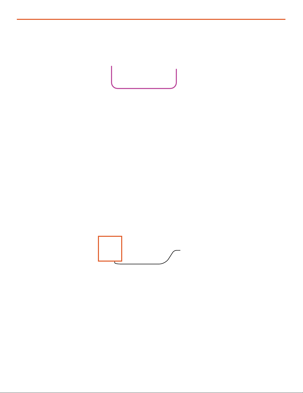
3. Connect the PRO-Verter to a 24VDC Expander Pak(s) using a 24VDC Inter-Connect Cable.
Inter-Connect Cable
Figure 5. Connecting an Expander Pak and the PRO-Verter
1. Connect the PRO-Verter to a PC with a straight-through CAT5 Ethernet cable between the
external MODEM or TECH port and an Ethernet port on a PC (lower right box in Figure 6). Green
lights on both ends of the cable indicate a good connection. (If the connection is not good, use a
crossover cable to connect the PC to the PRO-Verter.)
2. Congure the PC to communicate via a static IP address. See “Setting a PC Static IP Address”
section for instructions.
Connecting a PC Directly to the RMK
Figure 6. RMK connected to PC
3. Turn on the PRO-Verter main power switch. Note: Connecting all cables and components with
the power on may result in a failure of the RMK to communicate. Turn on the power only after all
connections have been made.
Note: The time it takes for the RMK to “boot up” and begin to communicate with the PC may
vary signicantly, from seconds to many minutes.
|7
January 2020 |Solar Stik®, Inc.
Operator and Maintenance Manual for PRO-Verter RMK LAN
OPERATOR INSTRUCTIONS
Viewing the System Data
The “PRO-Verter RMK (S1XXX)*: Current Settings” window is the rst window displayed. This page
reports the current settings for the PRO-Verter including the Inverter Settings, Remote Settings,
Auto Generator Start Settings, and the Battery Monitor. These values were set at the factory and few
can or should be changed.
*Each RMK is serialized S1XXX. The serial number unique to that RMK will be displayed
automatically in the “Current Settings” title.
All windows and values reported by the GUI are read only.
Figure 7. Home Screen and Current Settings of the RMK graphical user interface
The System data collected by the RMK is displayed in the RMK GUI. The GUI menu bar provides
options for three (3) windows:
“Current Conditions” “Historical Data”“Current Settings”
The default IP address for the RMK is 192.168.1.200. Type “192.168.1.200” into the address bar of a
web browser. The “Current Settings” page of the RMK graphical user interface (GUI) should appear
after a moment or two (Figure 7).
Current Settings Page

Operator and Maintenance Manual for PRO-Verter RMK LAN
January 2020 |Solar Stik®, Inc.
8 |
PRO-Verter Current Conditions (real-time)
This (and the facing) page is updated every 10 seconds and gives an overall view of the system. The
left-hand side of the screen displays the conditions as they are in real time.
• Data Supplied By Battery Monitor
This is both real time and average data from the last 24 hours. The volts, amps and watts are DC
values.
• Data Supplied By Inverter
This is real time data from the inverter. Most of the data supplied are critical component
temperatures, AC output and battery status.
• AGS/Generator
This section provides data regarding the generator auto start/stop system if it has been used.
• Memory
At the lower left corner of the page is a small window showing how much storage space is being
used, and how much is left on the internal drive.
Current Conditions Page (left side of screen)
Figure 8. Current Conditions Page (left side)

|9
January 2020 |Solar Stik®, Inc.
Operator and Maintenance Manual for PRO-Verter RMK LAN
Current Conditions Page (right side of screen)
24-hour Data
The right-hand side of the “Current Conditions” screen displays a 24-hour rolling minimum,
maximum, and average (statistical mean) for:
• Data Supplied by Battery Monitor (BMK)
• Data Supplied by Inverter/Charger
• Auto Generator Start Circuit Conditions
• Alarm Controls: Alarm will sound with any System Fault
The RMK noties the user of fault conditions when they arise. Faults include but are not limited
to: generator start failure, inverter overtemperature, charger overtemperature, low battery, and lost
Ethernet connection.
A list of inverter faults with codes can be found on the Historical Data Page. Fault codes are
recorded in the data les and reported in the table of Fault and Status Codes.
Figure 9. Current Conditions Page (right side)

Operator and Maintenance Manual for PRO-Verter RMK LAN
January 2020 |Solar Stik®, Inc.
10 |
Historical Data Page
The RMK user interface provides multiple ways to access, view, and report the historical data that
are collected. Clicking the box next to a month will call up a sub-page that displays the information
for that month in graphical form (see Figure 10). Note: The graphs shown here contain no real data.
They are shown only for the purpose of illustrating what graphs will be present. In addition to the
graphs, the les that contain the graphed data can be downloaded as .txt or .csv les.
Access to
historical
data les
Figure 10. Historical Data Page
Fault and Status
Code References
can also be found
by clicking this
link. See the next
page.

|11
January 2020 |Solar Stik®, Inc.
Operator and Maintenance Manual for PRO-Verter RMK LAN
Fault Codes and Inverter Status Codes
Data les contain Inverter Fault and Status Codes along with all of the other parameters from
the RMK. The table below is the key for the Fault and Status Codes. Note: The “FAULT” column
(Column T) in log les extracted from the RMK include fault codes not listed below. If fault codes
other than those shown below are reported by the RMK User Interface or encountered when
searching the log les, please contact Solar Stik Technical Support.
Table 1. Inverter Fault and Status Codes
Note: Fault codes ranging from 250-
255 may indicate that the RMK has been
connected incorrectly. Check/ensure that
all of the connections and cable types are
correct.

Operator and Maintenance Manual for PRO-Verter RMK LAN
January 2020 |Solar Stik®, Inc.
12 |
Use the following steps to congure the network settings on the PC that is connected directly to the
RMK.
The following screen capture images show how the process appears on a Windows 10 laptop.
Please note that the names of the settings windows will vary based on the user’s hardware, installed
driver for that hardware, and the version of Windows.
1. Click the Start button, type “control panel” into the search window, then click “Control Panel” in
the search results.
Click
Setting a PC Static IP Address
Figure 11. “Control panel” search

|13
January 2020 |Solar Stik®, Inc.
Operator and Maintenance Manual for PRO-Verter RMK LAN
Figure 12. Control Panel window
2. Click “Network and Internet”.
Click
3. Click “Network and Sharing Center”.
Click
4. The various active networks will appear in the window. Click “Ethernet”.
Figure 13. Network and Internet window
Figure 14. Network and Sharing Center window
Click
Operator and Maintenance Manual for PRO-Verter RMK LAN
January 2020 |Solar Stik®, Inc.
14 |
6. Click the radio button in front of “Use the following IP address:” if it is not already selected.
If using the default IP address for the RMK, which is 192.168.1.200, set the PC IP address to
192.168.1.xxx. Note: The last 3 digits can be any number between 1 and 254, with the exception
of numbers already associated with other devices (including the RMK) on the network. The one in
Figure 16 is set to 240.
Set the other address per Figure 16. When nished, click OK or Close in the three (3) windows for
the changes to take effect.
Figure 16. Internet Protocol Version 4 Properties window
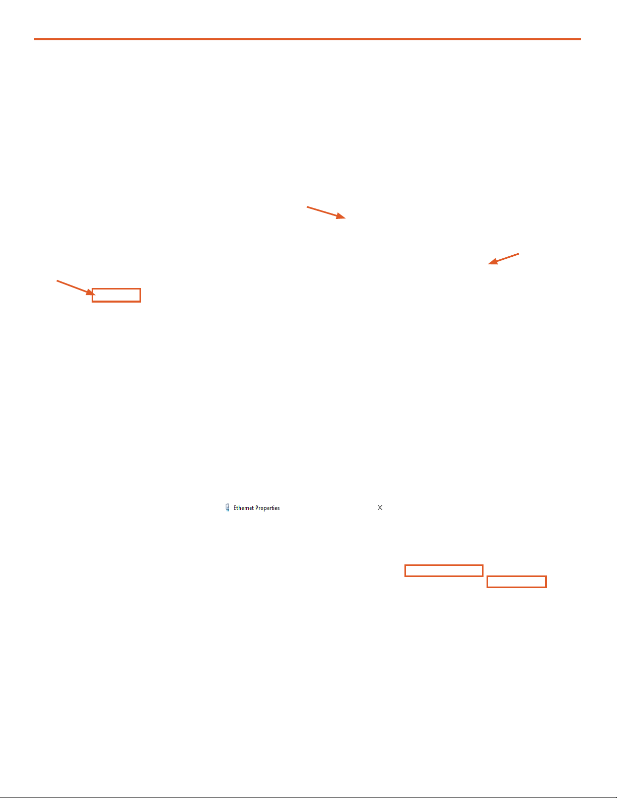
5. In the Ethernet Status window, click the Properties button. In the Ethernet Properties window,
click the “Internet Protocol Version 4 (TCP/IPv4)” box. If the box was already checked, click to
uncheck the box and then click again to check the box so the Properties button becomes active.
Then click the Properties button.
Figure 15. Ethernet Status and Ethernet Properties windows
Click
1. Click
2. Click
when
button
isactive

|15
January 2020 |Solar Stik®, Inc.
Operator and Maintenance Manual for PRO-Verter RMK LAN
• The logs folder contains historical records of all data from the RMK since the last time it was
uploaded from the RMK by plugging in the USB drive. The historical records are both .txt and
.csv les created daily and consist of data captured every 10 seconds. The data in these les are
the same as the data displayed in the user interface.
• The interfaces file is used to congure networking. This le is not created by the RMK.
• The ipaddress.txt file is a log le that shows the current IP address of the RMK. When using
DHCP, the router-assigned IP address can be discovered by reading this le. Note: IP addresses
may change after a reboot if the IP address in the interfaces le is different from the current IP
address.
• The interfaces.bak file is the interfaces le that was used previously to congure the RMK.
Figure 17. List of les on the USB drive
Files on the USB Drive Included with the System
A USB drive included with the system will contain the les listed as shown in Figure 17. The les are
in a folder with the same name as the RMK Serial Number (S1002 in the gure below).
Connecting the RMK to a Network via a Router
The RMK is congured to connect to a DHCP network by default.
Connect the RMK to a router using a straight-through Cat5 Ethernet cable.
Open a command prompt window and type in “ipcong/all” to nd the IP address that the DHCP
router assigned to the RMK. Type this IP address into the address bar of a web browser to view the
system data.
If a DHCP network is not available or desired, the RMK settings can be reprogrammed (see
instructions “Editing the Interfaces File” section).

Operator and Maintenance Manual for PRO-Verter RMK LAN
January 2020 |Solar Stik®, Inc.
16 |
Editing the Interfaces File
• Lines 1 and 2 are for the loopback interface and should not be changed.
• Lines 4 and 5 congure the Ethernet port to use DHCP. If a DHCP server is available, this will
be the default address and will be assigned by the router. If DHCP is not desired, comment out
lines 4 and 5. (To comment a line out, place a “#” character at the beginning of the line.)
• Lines 7–10 are used to congure an alias on the Ethernet port so that a static IP address can be
used. The default address as shipped is 192.168.1.200 and the netmask is 255.255.255.0. The
static IP address can be changed to match the user’s network.
Figure 18. Interfaces le
“Interfaces” is a simple Unix script text le that can be opened and edited with the text editor
Notepad++. Do not edit using word processing programs like MS Word. Note: The interfaces le
does not have a le extension.

|17
January 2020 |Solar Stik®, Inc.
Operator and Maintenance Manual for PRO-Verter RMK LAN
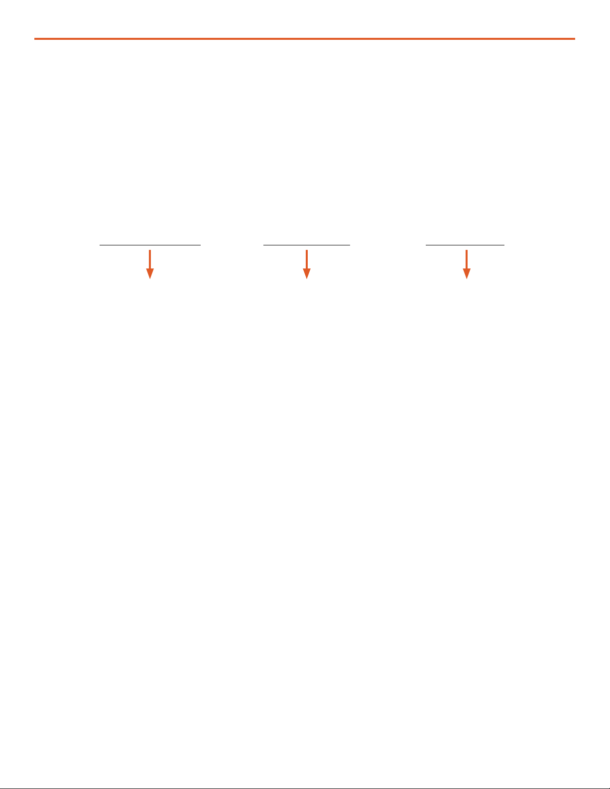
RMK
recognizing
the USB
drive
Uploading
info from
the USB
drive
(removed)
Cycling the
power to
the RMK
Setup
complete
Figure 19. Updating the RMK’s interfaces le
When a USB drive is inserted into the RMK,
the RMK looks for a folder with the RMK serial
number. If one does not exist, one is created.
The folder will be populated with log data and a
few other les (see Figure 17). If the USB already
contains the serial number folder, the les in this
folder will be updated.
1. Plug the USB drive into any of the four (4)
USB ports; they are all equal. The green LED
(circled in orange) on the lower right corner
of the RMK will turn off temporarily.
2. The LED will turn to orange while the RMK
reads the interfaces le and writes any
system data that have been logged by the
RMK to the USB drive. This process may
take several minutes.
3. When the process is nished, the LED will
return to green.
4. With the USB drive in the RMK and the LED
green, remove the NEGATIVE lead from the
5A 24VDC post.
5. Reconnect the lead. The LED will turn red.
Wait for the LED to turn green. This may take
several minutes.
6. Remove the USB drive.
Updating the Interfaces File in the RMK
For the interface le changes to take effect, the
RMK must be rebooted. This is accomplished
by cycling the power.
The RMK is now accessible to a network at the
reprogrammed IP address. Enter the new IP
address into a web browser to access the interface.
Waiting for
changes to
take effect
in the RMK
Note: The log les are extracted from the RMK onto
the USB storage device during this process. If the
data log les are large and numerous (Figure 8 lower
left), this process may take a long time (up to and
over an hour). The long wait can appear like the
RMK is frozen. Be paitient. Do not dismount the USB
storage device before sufcient time has been given
for the transfer.

Operator and Maintenance Manual for PRO-Verter RMK LAN
January 2020 |Solar Stik®, Inc.
18 |
Using the LED Indicators to Determine the RMK’s Status
TROUBLESHOOTING PROCEDURES
There is a bi-color LED indicator on the side of the RMK (next to the Ethernet port) to indicate
the RMK’s status. When the device is rst powered up, the LED blinks red and green while going
through a self-test. Once the self-test is complete, use the table below and the LED indicator to
determine the RMK’s operating status.
If the RMK device does not function correctly, use the tables below to help nd a solution.
Figure 20. Functions of LEDs below the Ethernet port
Normal operation is amber or green for the Link LED and periodic ashing of the
Activity LED.
Link Activity
Ethernet port
rst connected
Table 2. RMK LED Indicator Guide
Table 3. Link and Activity LED Meanings
8 © 2011 Magnum Energy, Inc.
4.0 Using LED Indicators to Determine MagWeb’s Status
4.2 MagWeb Wired Ethernet LED Status
4.2.1 LEDs Below the Ethernet Port
Normal operation is amber or green for the Link LED and periodic flashing of
the Activity LED.
Note: Refer to Figure 4-1 (Back View) to determine the positions of the
Activity and Link bi-color LEDs within the MagWeb’s Ethernet port.
Table 4-2, Functions of LEDs Below the Ethernet Port
Link LED Activity LED
Color Meaning Color Meaning
Off No Link Off No Activity
Amber 10 Mbps Amber Half Duplex¹
Green 100 Mbps Green Full Duplex²
Note 1 - Data transfers between Magnum’s servers and the MagWeb system
can only transmit in one direction at a time (not simultaneously).
Note 2 - Data transfers between Magnum’s servers and the MagWeb system
can transmit in both directions at the same time (simultaneously).

|19
January 2020 |Solar Stik®, Inc.
Operator and Maintenance Manual for PRO-Verter RMK LAN
Before using the information below to troubleshoot, review the LED indicator guides in Table 2 and
Table 3.
Most issues arise when minor connection problems exists.
• Is the RMK connected to an “always on” internet connection?
• Is the RMK attached to a DHCP network to assign the address?
• Is the PRO-Verter powered up and properly connected to the RMK? Consult Connection
Diagram
Operating the PRO-Verter without the RMK
It may be necessary to use the PRO-Verter without the RMK. If this is the case, use an RJ11
Crossover cable to connect the REMOTE and INVERTER ports on the upper right-hand corner of
the PRO-Verter AGS Faceplate. Note: This cable MUST BE a “crossover” RJ11 cable for proper
function. A “straight” RJ11 cord will not work.
Figure 21. RJ11 Crossover wire connecting the REMOTE and INVERTER ports
Common Problems During Startup

Operator and Maintenance Manual for PRO-Verter RMK LAN
January 2020 |Solar Stik®, Inc.
20 |
RMK LAN Troubleshooting and Repair
II. Check the Coin Cell Battery
If the RMK LAN does not power up and the status LED does not emit light, the fault could be a
tripped PRO-Verter breaker, the coin cell battery, the fuse, or the microSD card in the microcontroller.
To determine which is the problem and how to resolve it, use the procedures in this section.
2. Remove the four (4) fasteners from the end of the RMK housing using a #2 cross-tip screwdriver.
Figure 22. RMK on PRO-Verter Faceplate
Figure 23. Fastener and status LED locations
Status LED
I. Check the DC OUT 5 A Breaker
1. The circuit supplying power to the RMK has a 5-amp
breaker. The LED above the breaker reset button will
emit green light if not tripped. The LED will be unlit if
the breaker has been tripped. If the breaker is tripped,
press the reset button. The LED will emit green light.
If the LED for the 5 A breaker is green but the RMK
does not power up, remove the RMK from the PRO-
Verter and proceed to step 2.
Remote
Monitoring Kit
(RMK)
DC OUT
Breaker
5 A
24 VDC OUT
5 A
RMK Power
Cable
Figure 24. Removing RMK fasteners
Table of contents
Other Solar Stik Batteries Pack manuals

Solar Stik
Solar Stik 24VDC LI BOS 500-120 User manual

Solar Stik
Solar Stik 50-000335 User manual

Solar Stik
Solar Stik 24VDC POWER HUB 2400 Installation instructions

Solar Stik
Solar Stik 24VDC Li ESM 2000 Installation instructions

Solar Stik
Solar Stik Li Expander Pak 2400 User manual

Solar Stik
Solar Stik BOS 2000-120-5199 User manual

Solar Stik
Solar Stik 24VDC LI EXPANDER PAK 1300 Installation instructions


