Sanyo Denki SANUPS E11A102 Series Use and care manual

1
This procedure contains instructions for replaceing the battery pack that is installed in the UPS main unit.
When the battery pack arrives, check the model number shown in the packaging box.
UPS
Battery Pack
Voltage
MODEL No.
Mass
E11A102*
BPE11A102A00
Appox. 6 kg
24V
E11A152*
BPE11A152A00
Appox. 9 kg
36V
E11A202*
BPE11A202A00
Appox. 12 kg
48V
E11A302*01*,
E11A302*11*
BPE11A302A00-1
Appox. 16 kg
60V
E11A302*02*,
E11A302*12*
BPE11A302A00-2
Appox. 20 kg
72V
<Appearance of battery pack>
CAUTION
!
•Please replace the battery periodically. Batteries that have expired the replacement period may cause a fire.
•The weight of the battery pack is shown in the table. Please wear insulated gloves, safety shoes when replacing the battery.
Be careful not to injure yourself; dropping it into your feet or pich your hands when handling the battery pack. Bodily injury may occur
if not properly handled. Replacing the battery for E11A302 model should be done by two or more people. Please protect your back to
avoid back pain.
•The voltage that is listed in the table above is always occuring on the battery terminal, so do not touch them with your hands or
short-circuit them. There is a risk of electrick shock or injury. Also, for safety, use insulation method, such as attaching vinyl tape to
the used battery pack connector.
•To safely replace the battery pack, please refer to the E11Ainstruction manual.
M0012299
B
Ba
at
tt
te
er
ry
y
R
Re
ep
pl
la
ac
ce
em
me
en
nt
t
P
Pr
ro
oc
ce
ed
du
ur
re
e
f
fo
or
r
E
E1
11
1A
A
•It is not covered by our warranty if the damage is caused by an agent other than our company during replacement.
When replacing the battery performed by an agent other than our company, shall be responsible for the damage done.
Damage includes damage to equipment and load equipment, data damage and loss profits. However, it is not only limited to these.
•E11A battery pack is especially designed for our UPS. Do not use a non-specified battery. Also, do not mix old batteries to new one
or use batteries with different manufacturing date. It may cause battery life shortage, leakage and heat generation.
Note on battery replacement
The packaging box is used to send back the used battery pack,
do not dispose it. (For Japan)
Scale
E11A302
Battery pack
E11A102
Battery pack
E11A152
Battery pack
E11A202
Battery pack

2
①Check the state of usage
②Replace the battery pack with the following procedure depending on the state of the load device connected to the E11A.
Continued on page 3.
If you can stop the load equipment
Replace the battery pack. ⇒1.Replacing the battery pack
If the load device cannot be stopped.
You can also replace the battery pack
without stopping the load. However, it is
recommended that you do it in a short
period of time because you will not be able
to back up when an input abnormality such
as a power outage occurs during
replacement.
E11A stop.
For more information on
stopping procedures, please
refer to E11A’s Instruction
Manual.
Stop the load equipment.
If the E11A*U model is used as a ULStandard Product and CE Marking Conformity Product, you may not
be able to replace the battery pack by yourself due to a standard restriction. Be sure to ask a service
representative.
CAUTION
Use as UL Standard
Not use as UL Standard
Please ask a service representative
Exchange the battery

3
Continued from page 2
Reset the battery information. ⇒2.Resetting the battery information.
Start the load equipment. ⇒3.[Caution for storage battery replacement ] label
Start E11A
Please refer to the
instruction manual of E11A
for details of the startup
procedure.
Start the load equipment.
Dispose the used battery pack. ⇒4.Disposing of the used battery pack.
(1)If the battery pack is defective, discontinue use and contact the retailer or our company.
(2)Battery storage and charging of the battery
・Battery disintergrate during storage, so please use as soon as possible.
・Store the battery in a dry place where the temperature is low.
・During storage, please charge once at least every 6 months (storage temperature: 25℃)
and before use.
・Please charge with the UPS charger. Refer to E11A instruction Manual “Charging the UPS”
(3)Battery Transportation and Handling
・As a rule, avoid abnormal vibrations or shock during transportation.
・Do not use a battery pack that has been accidentally dropped, or a battery pack that has been strongly impacted.
Handling Precautions for Battery Pack
Replace the battery pack. ⇒1.Replacing the battery pack.

4
1
1.
.R
Re
ep
pl
la
ac
ci
in
ng
g
t
th
he
e
B
Ba
at
tt
te
er
ry
y
P
Pa
ac
ck
k
Replace the battery pack with the following steps.
①Remove the UPS front cover.
②Remove the one screw on the right side of the battery cover and remove the battery cover.
③Set the Switch Forced Bypass to “Bypass” side.
④Unplug the battery connector.
⑤Pull out the battery pack.
⑥Paste the tape from new battery pack to used battery pack’s connector after remove the tape.
Battery Cover
②Loosen the screw and slide the
battery cover in the direction of the
arrow. The screw is a fall prevention
screw, so it can’t come off the
battery cover.
⑤Pull out the battery
pack out.
④Disconnect the battery connector.
⑥Attach the tape and insulate it.
CAUTION
!
The weight of the battery pack is shown in the table on page 1. The battery pack
does not have a drop stopper. Pull the battery pack slowly, hold the bottom with
both hands, and be careful no to drop it. Also, be careful no to pinch your hands
when dealing with battery packs.
The E11A302 battery pack has a scale at the top shown on page 1. When the
scale is seen, keep the bottom part supported with both hands, and be careful
not to drop it.
Procedures ③,⑨and ⑩are required for UL Standards
For service personnel only
③Slide the switch to
“Bypass”.
Not use as UL or CE Standard
Use as UL or CE Standard
(Authorized person only)
①Remove by sliding in
the direction of the
arrow by holding two
places of ● strongly.

5
⑦Insert the new battery pack into the UPS.
⑧Plug in the battery connector.
⑨Set the switch Forced Bypass to “Inverter” side.
⑩Make sure that LED【OUTPUTgreen】and【INV.ON/STAND
BY
green 】on the front panel are blinking.
for over a second.
⑪Confirm the switch Forced Bypass is on the “Inverter” side, the LED【OUTPUT green 】and【INV.ON/STAND
BY
green 】
on the front panel are lit (when the UPS is in operation).※
⑫Install the battery cover.
⑬Fit the front cover
CAUTION
!
•Do not force to insert the battery connector if it is in a
different orientation. Damage to the connector may
cause electric shock.
•Be careful not to pinch your hands when securing the
cover.
⑧Plug in the battery connector until you hear
a click sound.
The diagram shows the case of E11A102.
The size of the battery pack depends on the model.
Please see the size on page 1.
When it is not used as a UL
Standard.
When it is used as a UL Standard
(for service personnel)
If you have an additional battery module, replace the
battery after ⑧.
⑦Insert the battery pack
in the direction of the
arrow.
If the Forced Bypass is on ”Bypass”side, set it to “Inverter”
side.
If the UPS is in operation, the【INV.ON/STAND BY green】is blinking.
Press for 1 second and check if【INV.ON/STAND BY green】
turns on, then proceed to step ⑫.
⑫Insert the tabs into the slots and
slide it to the right until you hear a
click sound. Secure it with the
screws.
For service personnel only
⑨⑪Slide the switch
to “Inverter”.
⑬Push the front
cover until the claw
hook to the left side.
In case of E11A302 model, make sure a scale
measurement while removing battery pack.
There is possibility to drop your foot suddenly,
if you are not checking.
Caution
Caution

6
2
2.
.R
Re
es
se
et
tt
ti
in
ng
g
t
th
he
e
B
Ba
at
tt
te
er
ry
y
I
In
nf
fo
or
rm
ma
at
ti
io
on
n
Reset the Battery information after replacing the battery installed in the UPS. The following actions will reset all battery information (such
as expected battery lifetime, battery operating time, power outage count, etc.): If you have additional batteries, do so after replacing all
the battery packs.
①Make sure the UPS is in the following state.
②Press for 3~4 seconds and release it when the buzzer alarms.
③Promptly press the (3 second or less) several times until the five LEDs enclosed by are in the blinking pattern as
shown in the figure.
④Promptly press the (3 second or less) several times until the four LEDs with are in the blinking pattern shown in the
figure.
Press promptly
Press promptly
Reset the battery information after replacing the
battery. If you do this incorrectly, the battery life warning
will not display correctly.
UPS is in user setting mode
Buzzer: “beep, beep”
:【BATT.LOW】【 25】Blinking both or either one
:【INPUT】Blinking
The MAIN SW on the back side is set to “ON”※1
【INV.ON/STAND BY green】and【OUTPUT green】are
not blinking. ※2
※1.
can be operated either “ON”or “OFF”state.
※2
. If
blinking, the Forced Bypass switch is set to “Bypass”.
Set it to “Inverter”and operate again.
POINT
:Off
:Blinking
Indicator
Press 3~4 seconds and release it
when the buzzer rings “beep,
beep”.
Every time you press or the blinking pattern changes.
If you push too far and slip through the LED blinking pattern
you want to select, press repeatedly until the LED blinking
pattern you want to select again appear.
POINT
Example:LED blinking pattern when set the setting value to
reset
Setting Value
LED blinking
pattern
Details
Do not reset
●○○○
Do not reset
Reset
○●○○
Reset Battery Information
Reset the battery information (expected battery lifetime,
battery operating time, power outage count, battery life LED
indication) after replacing the battery.
Initial Setting

7
Please release it as soon as the buzzer alarms ”beep, beep”, it
means that the setting is saved in the UPS and resume to normal
operation.
After resetting, the setting are automatically returned to
“Do not reset”.
⑤Press for 3~4 seconds and release it when the buzzer alarms.
Press 3~4 seconds and
release it when the buzzer
rings “beep, beep”.
If【BATT.LOW】is still blinking, thebattery information is not reset
correctly. Please reset it again.
Caution

8
3
3.
.
F
Fi
il
ll
li
in
ng
g
i
in
n
t
th
he
e
”
”C
Ca
au
ut
ti
io
on
ns
s
f
fo
or
r
S
St
to
or
ra
ag
ge
e
B
Ba
at
tt
te
er
ry
y
R
Re
ep
pl
la
ac
ce
em
me
en
nt
t”
”
L
La
ab
be
el
l
Please fill in the ”Cautions for Storage Battery Replacement” label that is attached to the UPS body for the next replacement date
(month/year).
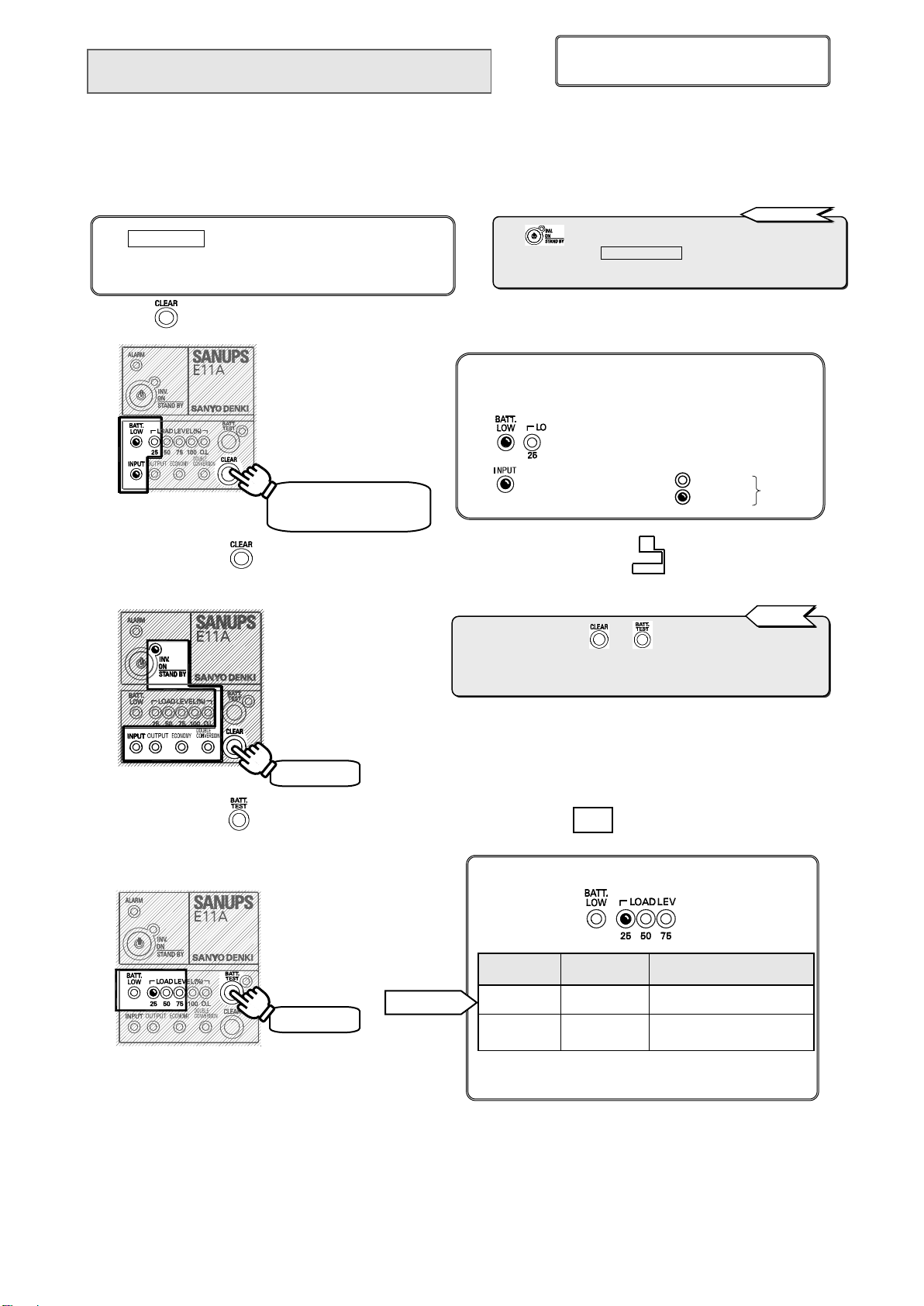
①Fill in the blank in the second row for the next replacement date (month/year).
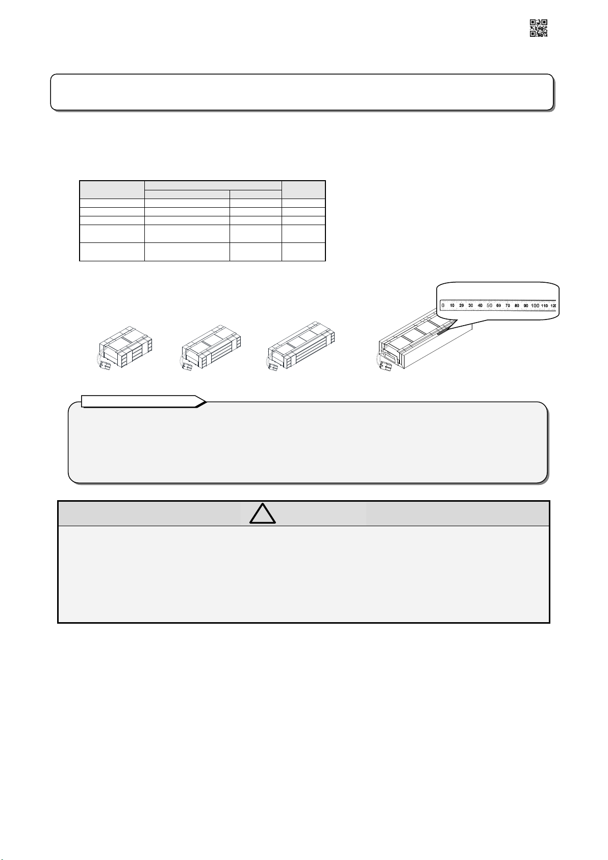
Check the right table for the battery replacement period
corresponding to the ambient temperature environment
where the UPS will be installed and fill in the month and
year of the next replacement in the ”Cautions for Storage
Battery Replacement” label. Please write using marker that
is hard to erase such as oil proof pen or permanent marker
pen. The date in the first row is assumed as the month and
year when the battery was replaced.
Example of filling in the label with Ambient temperature of 25℃.
To be replaced on January 2015 ⇒the next replacement period is after four years and 6 months from the date of replacement:
2019 year 6month →”JUN.””2019”
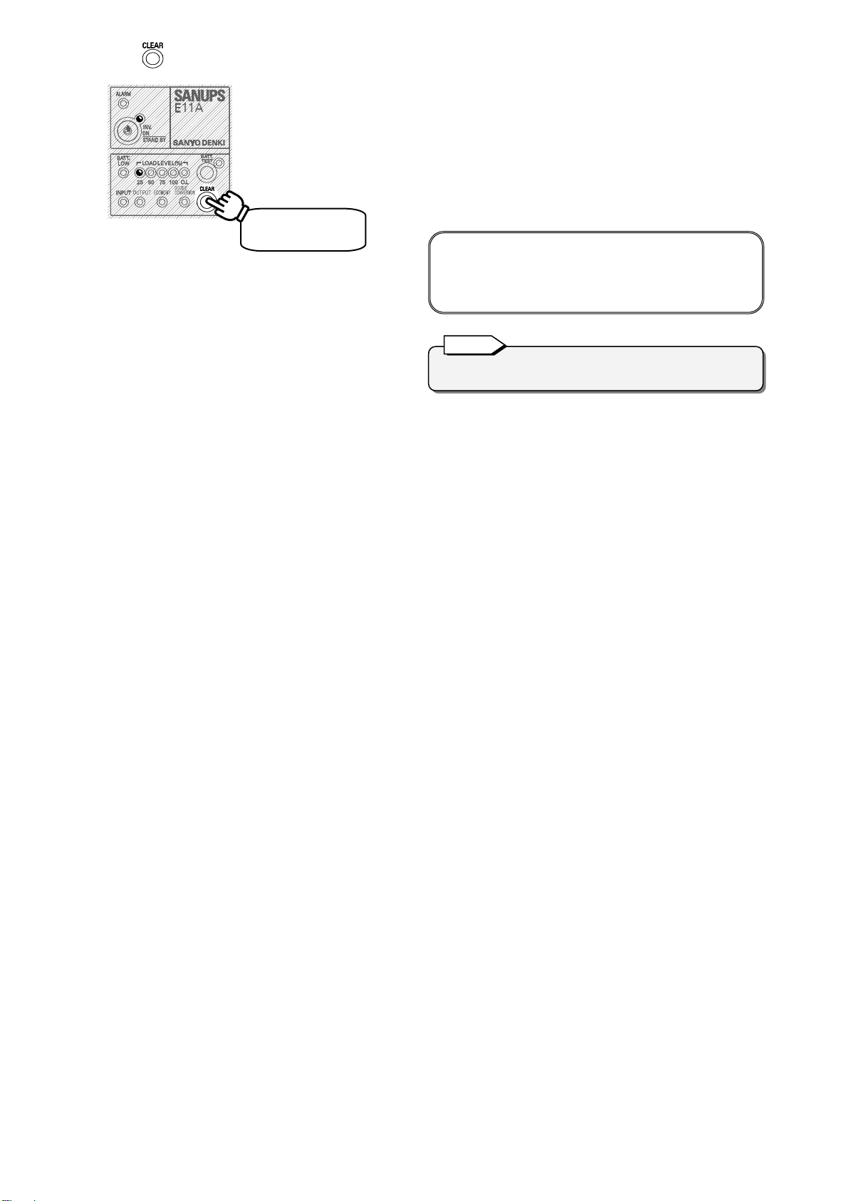
「Cautions for Storage Battery replacement」Label
②If the second row is already filled in, write the replacement date in a memo and attached it in a visible place that is easy to see but
will not be a hindrance to UPS intake exhaust fan.
4
4.
.D
Di
is
sp
po
os
sa
al
l
o
of
f
u
us
se
ed
d
b
ba
at
tt
te
er
ry
y
p
pa
ac
ck
k
2019
JUN.
※Please fill in with marker that
is hard to erase such as oil
proof pen.
End of the procedure for replacing the battery pack.
Fill in
About Battery disposal method
The batteries used in this product are lead type batteries which are a reusable resource. Please cooperate in the
recycling when replacing or disposing the used batteries. Dispose the used batteries according to the instructions.
To dispose the used batteries, contact your nearest sales representative, an authorized industrial waste handling
company, or repack them in their original packaging box and send them to your supplier. (An extra charge is required)
Ambient
Temperature
Expected Battery
Life
Battery replacement
Period
25℃
5 years
4.5 years
30℃
3.5 years
3 years
35℃
2.5 years
2 years
40℃
1.7 years
1.5 years
Pb
This manual suits for next models
13
Table of contents
Popular Batteries Pack manuals by other brands

HUBBELL LIGHTING
HUBBELL LIGHTING Dual Lite PLD9M-2H Installation, operation & service instructions

NX
NX ENERGY BOX BEL9017 user manual

Hohm
Hohm Wrecker G2 Quick manual

C&D Technologies
C&D Technologies LIBERTY 1000 Series Installation and operating instructions

rivacase
rivacase RIVAPOWER VA2002 Instructions and warnings

Growatt
Growatt ARK 2.5H-A1 Quick installation manual