Solar Stik 50-000335 User manual

|1
October 2023 |Solar Stik®Inc.
OPERATOR MANUAL
FOR
PGA TOUR POWER MODULE & SOLAR SKIRT
Part Number: 21-0202306
DISTRIBUTION STATEMENT A. Approved for public release; distribution is unlimited.
P/N 50-000335

October 2023 |Solar Stik®Inc.
2 |
Operator Manual for PGA Tour Power Module & Solar Skirt
Contents
Product Safety Information and Instructions . . . . . . . . . . . . . . . . . . . . . . . . . . . . . . . . . . . 5
Electric Shock Hazard. . . . . . . . . . . . . . . . . . . . . . . . . . . . . . . . . . . . . . . . . . . . . . .6
General . . . . . . . . . . . . . . . . . . . . . . . . . . . . . . . . . . . . . . . . . . . . . . . . . . . . . . 6
Limitations on Liability. . . . . . . . . . . . . . . . . . . . . . . . . . . . . . . . . . . . . . . . . . . . . . .6
IMPORTANT PRODUCT SAFETY INFORMATION AND INSTRUCTIONS
Safety Information Labels . . . . . . . . . . . . . . . . . . . . . . . . . . . . . . . . . . . . . . . . . . . . . 7
First Aid Measures. . . . . . . . . . . . . . . . . . . . . . . . . . . . . . . . . . . . . . . . . . . . . . . . .7
Fire Hazard . . . . . . . . . . . . . . . . . . . . . . . . . . . . . . . . . . . . . . . . . . . . . . . . . . . . 8
Recommended Fire Extinguisher . . . . . . . . . . . . . . . . . . . . . . . . . . . . . . . . . . . . . . . . . 8
Environmental and Handling Precautions . . . . . . . . . . . . . . . . . . . . . . . . . . . . . . . . . . . . . 9
Water . . . . . . . . . . . . . . . . . . . . . . . . . . . . . . . . . . . . . . . . . . . . . . . . . . . . . . . 9
Impact . . . . . . . . . . . . . . . . . . . . . . . . . . . . . . . . . . . . . . . . . . . . . . . . . . . . . . .9
Dust . . . . . . . . . . . . . . . . . . . . . . . . . . . . . . . . . . . . . . . . . . . . . . . . . . . . . . . . 9
Heat . . . . . . . . . . . . . . . . . . . . . . . . . . . . . . . . . . . . . . . . . . . . . . . . . . . . . . . . 9
GENERAL INFORMATION, EQUIPMENT DESCRIPTION, AND THEORY OF OPERATION
Introduction . . . . . . . . . . . . . . . . . . . . . . . . . . . . . . . . . . . . . . . . . . . . . . . . . . . . 10
Equipment Description . . . . . . . . . . . . . . . . . . . . . . . . . . . . . . . . . . . . . . . . . . . . . . 10
Features and Specications. . . . . . . . . . . . . . . . . . . . . . . . . . . . . . . . . . . . . . . . . . . 10
SOLAR SKIRT SETUP AND OPERATION
Faceplate . . . . . . . . . . . . . . . . . . . . . . . . . . . . . . . . . . . . . . . . . . . . . . . . . . . . 16
The Information Plate (I-Plate). . . . . . . . . . . . . . . . . . . . . . . . . . . . . . . . . . . . . . . . . . 18
Theory of Operation . . . . . . . . . . . . . . . . . . . . . . . . . . . . . . . . . . . . . . . . . . . . . . . . 19
Modes of Operation . . . . . . . . . . . . . . . . . . . . . . . . . . . . . . . . . . . . . . . . . . . . . . . 20
Balanced Operation . . . . . . . . . . . . . . . . . . . . . . . . . . . . . . . . . . . . . . . . . . . . . . . 21
Cycling the Battery . . . . . . . . . . . . . . . . . . . . . . . . . . . . . . . . . . . . . . . . . . . . . . . 21
DC Circuits . . . . . . . . . . . . . . . . . . . . . . . . . . . . . . . . . . . . . . . . . . . . . . . . . . . 21
The Photovoltaic (PV) Charging Circuit . . . . . . . . . . . . . . . . . . . . . . . . . . . . . . . . . . . . . 22
Battery Management System (BMS) . . . . . . . . . . . . . . . . . . . . . . . . . . . . . . . . . . . . . . 23
OPERATOR INSTRUCTIONS
1. Fully Charge battery before use. . . . . . . . . . . . . . . . . . . . . . . . . . . . . . . . . . . . . . . . 24
Select Charging Method for System . . . . . . . . . . . . . . . . . . . . . . . . . . . . . . . . . . . . . . 24
2. Connect loads to the Power Module.. . . . . . . . . . . . . . . . . . . . . . . . . . . . . . . . . . . . . 25
4. Monitor the Power Module System status. . . . . . . . . . . . . . . . . . . . . . . . . . . . . . . . . . . 25
Monitoring Battery Status with the E Display . . . . . . . . . . . . . . . . . . . . . . . . . . . . . . . . . . 26
Connecting Additional Battery Capacity to the Power Module . . . . . . . . . . . . . . . . . . . . . . . . 27
Connecting Two (2) Power Modules . . . . . . . . . . . . . . . . . . . . . . . . . . . . . . . . . . . . . . . 28
Monitoring Connected Power Modules . . . . . . . . . . . . . . . . . . . . . . . . . . . . . . . . . . . . . 28
Simple Steps to Optimize Power Module Performance . . . . . . . . . . . . . . . . . . . . . . . . . . . . 29
Do Not Exceed Recommended Load Limits . . . . . . . . . . . . . . . . . . . . . . . . . . . . . . . . . . 29
Efciency Loss during Donor Charging . . . . . . . . . . . . . . . . . . . . . . . . . . . . . . . . . . . . . 29
Heat-related Derating . . . . . . . . . . . . . . . . . . . . . . . . . . . . . . . . . . . . . . . . . . . . . . 29
Handling the Power Module and Solar Skirt. . . . . . . . . . . . . . . . . . . . . . . . . . . . . . . . . . . 30
Storage . . . . . . . . . . . . . . . . . . . . . . . . . . . . . . . . . . . . . . . . . . . . . . . . . . . . . . . 30
Transportation . . . . . . . . . . . . . . . . . . . . . . . . . . . . . . . . . . . . . . . . . . . . . . . . . . . 31

|3
October 2023 |Solar Stik®Inc.
Operator Manual for PGA Tour Power Module & Solar Skirt
Power Module Transport . . . . . . . . . . . . . . . . . . . . . . . . . . . . . . . . . . . . . . . . . . . . . 32
Air . . . . . . . . . . . . . . . . . . . . . . . . . . . . . . . . . . . . . . . . . . . . . . . . . . . . . . . . 32
Ground. . . . . . . . . . . . . . . . . . . . . . . . . . . . . . . . . . . . . . . . . . . . . . . . . . . . . . 32
Other Issues . . . . . . . . . . . . . . . . . . . . . . . . . . . . . . . . . . . . . . . . . . . . . . . . . . . . 33
MAINTENANCE INSTRUCTIONS
Preventive Care and Maintenance . . . . . . . . . . . . . . . . . . . . . . . . . . . . . . . . . . . . . . . . 34
Water Intrusion Remediation . . . . . . . . . . . . . . . . . . . . . . . . . . . . . . . . . . . . . . . . . . . 34
In-storage Preventive Maintenance Checks and Services . . . . . . . . . . . . . . . . . . . . . . . . . . . 35
Power Module Air Intake Vent Filter Maintenance . . . . . . . . . . . . . . . . . . . . . . . . . . . . . . . 36
SUPPORTING INFORMATION
Technical Specifications . . . . . . . . . . . . . . . . . . . . . . . . . . . . . . . . . . . . . . . . . . . . . 37
General . . . . . . . . . . . . . . . . . . . . . . . . . . . . . . . . . . . . . . . . . . . . . . . . . . . . . 37
Connections . . . . . . . . . . . . . . . . . . . . . . . . . . . . . . . . . . . . . . . . . . . . . . . . . . . 37
Solar Charge Controller . . . . . . . . . . . . . . . . . . . . . . . . . . . . . . . . . . . . . . . . . . . . . 38
AC Charger . . . . . . . . . . . . . . . . . . . . . . . . . . . . . . . . . . . . . . . . . . . . . . . . . . . 38
Solar Skirt . . . . . . . . . . . . . . . . . . . . . . . . . . . . . . . . . . . . . . . . . . . . . . . . . . . . 38
DC/DC 24/48/600 . . . . . . . . . . . . . . . . . . . . . . . . . . . . . . . . . . . . . . . . . . . . . . . . 39
Safety . . . . . . . . . . . . . . . . . . . . . . . . . . . . . . . . . . . . . . . . . . . . . . . . . . . . . . 40
Environmental . . . . . . . . . . . . . . . . . . . . . . . . . . . . . . . . . . . . . . . . . . . . . . . . . . 40
Power Module Weights and Dimensions (L x W x H) . . . . . . . . . . . . . . . . . . . . . . . . . . . . . . 40
Solar Skirt Weights and Dimensions . . . . . . . . . . . . . . . . . . . . . . . . . . . . . . . . . . . . . . 40
The Inter-Connect System . . . . . . . . . . . . . . . . . . . . . . . . . . . . . . . . . . . . . . . . . . . . 41
LiFePO4Battery SDS. . . . . . . . . . . . . . . . . . . . . . . . . . . . . . . . . . . . . . . . . . . . . . . . 43
ABOUT SOLAR STIK, INC.
Contact . . . . . . . . . . . . . . . . . . . . . . . . . . . . . . . . . . . . . . . . . . . . . . . . . . . . . . . 51

October 2023 |Solar Stik®Inc.
4 |
Operator Manual for PGA Tour Power Module & Solar Skirt
List of Tables
Table 1. Power Module Ports Specications.................................................................................................................. 14
Table 2. Port and Load Limits......................................................................................................................................... 25
Table 3. Symptoms and Solutions for Power Module Issues......................................................................................... 33
Table 4. In-storage Preventive Maintenance Checks and Services ............................................................................... 35
Section Page(s) Description Date
First Published 7 Oct 2023
Revision History
List of Figures
Figure 1. 24VDC PGA Power Module ........................................................................................................................... 10
Figure 2. Solar Skirt ...................................................................................................................................................... 11
Figure 3. 24VDC PGA Power Module (front) ................................................................................................................ 12
Figure 4. 24VDC PGA Power Module (back).................................................................................................................. 12
Figure 5. 24VDC PGA Power Module (back).................................................................................................................. 13
Figure 6. Radar connector on (left), Solar connector on Solar Leash (middle) and Donor connector (right) ................. 13
Figure 8. 24VDC PGA Power Module (left side) ............................................................................................................. 13
Figure 7. 24VDC PGA Power Module (right side)........................................................................................................... 13
Figure 9. Solar Skirt ........................................................................................................................................................ 15
Figure 10. 24VDC PGA Tour Power Module Faceplate.................................................................................................. 16
Figure 11. 24VDC PGA Tour Power Module I-Plate ...................................................................................................... 18
Figure 12. Power ow from a top-down view of the interior of the Power Module........................................................ 19
Figure 13. Using the Power Module in Autonomous Mode............................................................................................ 20
Figure 14. Using the Power Module in Solar and AC Power Harvesting Mode ............................................................. 20
Figure 15. Using the Power Module in UPS Mode......................................................................................................... 20
Figure 16. Power Module charging ports ....................................................................................................................... 23
Figure 17. Connecting the Solar Skirt to the Power Module.......................................................................................... 24
Figure 18. Power Module E Display ............................................................................................................................... 25
Figure 19. Power Module Battery Power Switch............................................................................................................ 26
Figure 21. E Display........................................................................................................................................................ 26
Figure 20. Power Module Battery Breaker ..................................................................................................................... 26
Figure 22. Methods for connecting additional storage capacity to the Power Module ................................................. 28
Figure 23. Method for connecting two Li Power Modules ............................................................................................. 29
Figure 24. Power Module drain plug location................................................................................................................. 35
Figure 25. Cleaning and replacing the PGA Power Module air lters ............................................................................ 37
Figure 26. Inter-Connect Plug ........................................................................................................................................ 42

|5
October 2023 |Solar Stik®Inc.
Operator Manual for PGA Tour Power Module & Solar Skirt
Product Safety Information and Instructions
This manual contains important safety instructions that must be followed during the installation and
operation of this product. Read all instructions and safety information contained in this manual before
installing or using this product.
All electrical connections must be made using the proper polarized connectors.
While this product is designed for indoor/outdoor operation, the interior of the Power Module must not
be exposed to rain, snow, moisture, or liquids. Close and latch and/or lock the cases when the System is
unattended.
The Power Module is not eld serviceable beyond simple preventive maintenance. Do not attempt to
open or service the unit. If repair is needed, it must be returned to Solar Stik®, Inc. for service, or contact
your eld service representative (FSR).
Exercise caution when handling or operating the Power Module. Live power may be present at more
than one point.
Note: Battery chemistries and voltages must never be mixed within a single battery bank or
system.

October 2023 |Solar Stik®Inc.
6 |
Operator Manual for PGA Tour Power Module & Solar Skirt
• Do not short (+) and (-) terminal with conductors.
• Do not connect in series.
• Do not reverse the polarity.
• Do not mix different type batteries or mix new and old ones together.
• Do not open the battery module.
• Do not submit to excessive mechanical stress.
• Do not submerge the unit in water.
• Do not heat directly, solder, or throw into re. Such unsuitable use can cause leakage or spout
vaporized electrolyte fumes and may cause re or explosion.
• Immediately disconnect the batteries if, during operation, they emit an unusual smell, feel hot,
change shape, or appear abnormal in any other way.
General
Electric Shock Hazard
DON’T LET THIS BE YOU!
WARNING
Standing water around the electrical equipment and / or intrusion of water into the System
components can increase the risk of electrical shock.
Limitations on Liability
Since the use of this manual and the conditions or methods of operation, use, and maintenance of
this product are beyond the control of Solar Stik, this company does not assume responsibility and
expressly disclaims liability for loss, damage, or expense—whether direct, indirect, consequential, or
incidental—arising out of or in any way connected with such operation, use, or maintenance.
Due to continuous improvements and product updates, the images shown in this manual may not
exactly match the unit purchased.
This equipment CAN BE USED FOR CONNECTION WITH LIFE SUPPORT SYSTEMS OR OTHER
MEDICAL EQUIPMENT or devices; however, without limiting the generality of the foregoing, Solar
Stik makes no representations or warranties regarding the use of the System in connection with life
support systems or other medical equipment devices.

|7
October 2023 |Solar Stik®Inc.
Operator Manual for PGA Tour Power Module & Solar Skirt
Safety Information Labels
Your safety and the safety of others is very important.
Always read and obey all safety messages.
This is the safety alert symbol. This symbol alerts you to potential hazards that can kill you or
hurt you and others. All safety messages will follow the safety alert symbol and the word
“DANGER”, “WARNING”, or “CAUTION”. These words are dened as:
DANGER Indicates a hazardous situation which, if not avoided, will result in death or
serious injury.
Indicates a hazardous situation which, if not avoided, could result in death or
serious injury.
CAUTION Indicates a hazardous situation which, if not avoided, could result in minor or
moderate injury.
All safety messages will tell you what the potential hazard is, how to reduce the chance of injury, and
what can happen if the instructions are not followed.
WARNING
IMPORTANT PRODUCT SAFETY INFORMATION AND INSTRUCTIONS
This manual contains important safety instructions that must be followed during the installation and
operation of this product. Read all instructions and safety information contained in this manual.
Exercise caution when handling or operating equipment. Live power may be present.
First Aid Measures
EYE CONTACT: Immediately ush eyes with copious amount of water for at least 15 minutes. Seek
immediate medical attention.
SKIN CONTACT: Remove contaminated clothing and ush affected areas with plenty of water for at
least 15 minutes. Wash skin with soap and water. If skin irritation persists, call for medical attention.
INHALATION: Move to fresh air and seek immediate medical attention. Obtain medical advice.
October 2023 |Solar Stik®Inc.
8 |
Operator Manual for PGA Tour Power Module & Solar Skirt
Fire Hazard
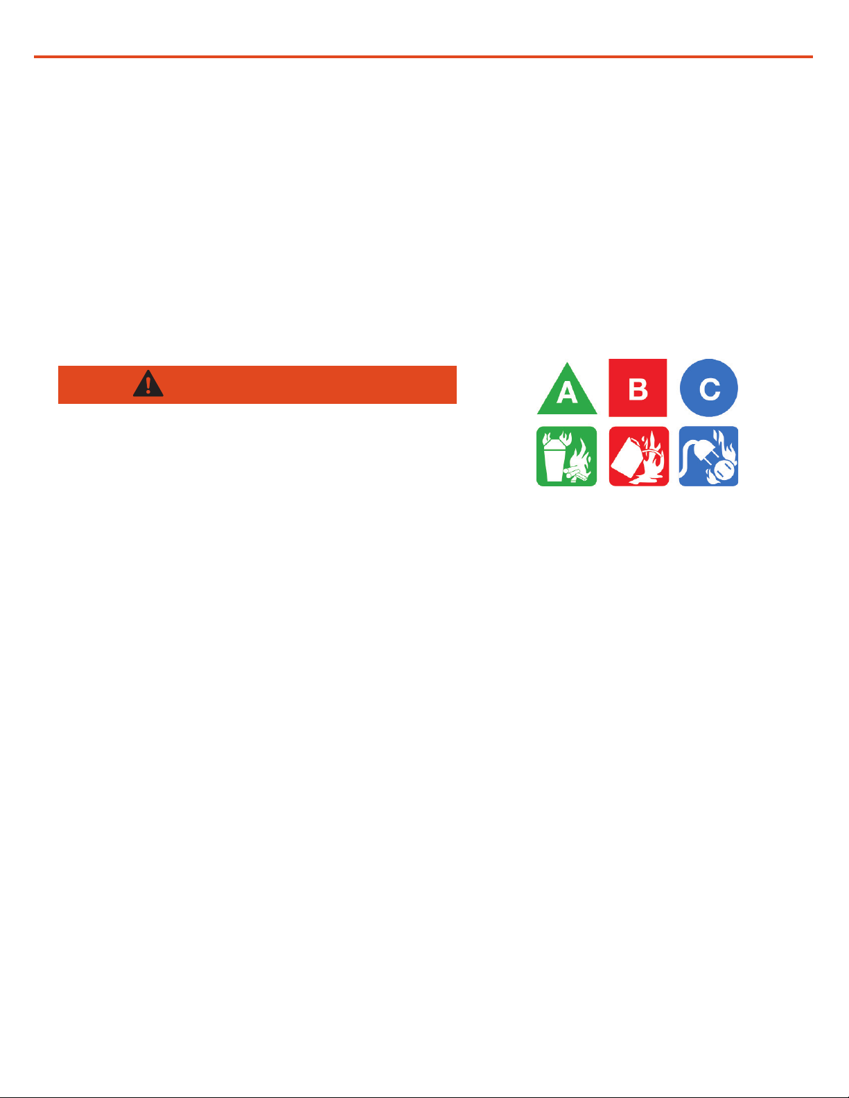
Fire Types
Class A fire - Fires in ordinary combustibles such as wood, paper, cloth, trash, and plastics.
Class B fire - Fires in ammable liquids such as gasoline, petroleum, oil, and paint.
Class C fire - Fires involving energized electrical equipment such as motors, transformers, and
appliances. Remove the power source and the class C re becomes a class A or B re.
Recommended Fire Extinguisher
Fire Extinguisher, Carbon Dioxide, 10 lb
Carbon Dioxide is a liqueed gas, which is highly effective for ghting class B and C res. These
extinguishers are ideal for areas where contamination and/or cleanup are a concern, such as data
processing centers, labs, and telecommunication rooms.
WARNING
Only CO2(Carbon Dioxide) re extinguishers should
be used with Solar Stik equipment.
Using the Fire Extinguisher
When using the extinguisher on a re, remember PASS:
Pull the pin.
Aim the nozzle or hose at the base of the re from a safe distance.
Squeeze the operating lever to discharge the re extinguishing agent.
Sweep the nozzle or hose from side to side until the re is out. Move forward or around the re as
the re diminishes.
Watch the area for reignition until the cause has been xed.
Large fires: Use large quantities of water to extinguish surrounding re and prevent further
propagation. If water is used on batteries in operation, caution should be taken to avoid the electrical
hazard that may be present.
SPECIAL FIRE FIGHTING PROCEDURES: Fireghters should wear self-contained breathing
apparatus. Use approved / certied vapor respirator to avoid breathing toxic fumes. Wear protective
clothing and equipment to prevent potential body contact with electrolyte solution. It is permissible to
use any class of extinguishing medium, specied above, on these batteries or their packing material.
Cool exterior of batteries if exposed to re to prevent rupture.
PARTICULAR HAZARDS RESULTING FROM EXPOSURE TO THE SUBSTANCE/PREPARATION,
TO COMBUSTION AND GAS PRODUCTS: The cell can spout vaporized or decomposed electrolyte
fumes with re when heated over +100°C (+212°F) or disposed of in re. Solvents within the
electrolyte are ammable liquids and must be kept away from any kind of ignition source.
Risk of irritation occurs only if the cell is mechanically, thermally, or electrically abused to the point of
compromising the integrity of the enclosure. If this occurs, irritation to the skin, eyes, and respiratory
tract may occur.
|9
October 2023 |Solar Stik®Inc.
Operator Manual for PGA Tour Power Module & Solar Skirt
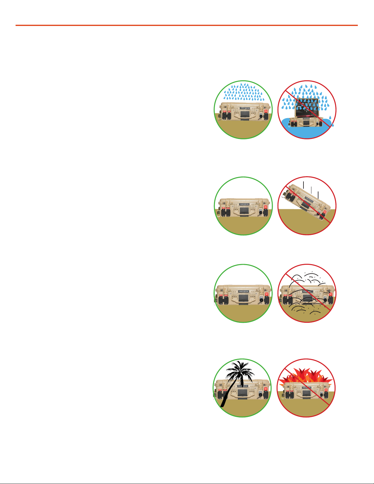
Environmental and Handling Precautions
All Solar Stik components are ruggedized, yet there are a few things the operator can do to prevent
failures and prolong the operational life of the product.
Water
If outdoor operation is necessary, the lids
of all components should be closed and
latched whenever possible. Lids should only
be open to access operator controls and
closed at all other times.
Impact
Equipment should not be dropped onto hard
surfaces at a height greater than one foot
when transporting or during operation.
Dust
• Air intake lters should be cleaned once per
month, or more frequently when conditions
warrant.
• As a general rule, minimize exposure to
high levels of particulates by exercising
common-sense placement.
Heat
Heat and solar loading reduce efciency,
cause Power Module derating, and shorten
life expectancy. Shade the Power Module to
prevent the negative effects of heat.
October 2023 |Solar Stik®Inc.
10 |
Operator Manual for PGA Tour Power Module & Solar Skirt
GENERAL INFORMATION, EQUIPMENT DESCRIPTION,
AND THEORY OF OPERATION
Introduction
The 24VDC PGA Power Module (Figure 1) and Solar Skirt combine power management and energy
storage into a single, rugged, portable, and expandable power system for PGA applications.
The Power Module accepts power from DC generation sources including renewables and vehicles, and
is universally compatible with single phase AC inputs (90-260 VAC) allowing connection to any generator
or worldwide grid AC power source.
While designed as a fully-autonomous power system, the System offers unique capabilities that allows
exibility for the operator.
Figure 1. 24VDC PGA Power Module
Power Module Features:
• Provides power for PGA golf course operational loads
• 60 Ah (1.4 kWh) of energy storage capacity providing
long periods of autonomous operation
• Lithium iron phosphate battery cell chemistry
This manual is crafted to provide the user with a comprehensive understanding of the principles
of operation, proper setup and use, operational tips, and safety procedures for the Power Module.
Successful operation and maintenance depends on a complete understanding of how the Power
Module works, and how to effectively integrate the Power Module into a given situation. Please read
this manual thoroughly before operating the Power Module.
Adherence to operation and safety protocols will yield optimal performance from the Power Module for
many years. Procedures for operation, preventive care and maintenance, and troubleshooting are all in
this manual.
P/N 16-0502101
Equipment Description
Features and Specifications
|11
October 2023 |Solar Stik®Inc.
Operator Manual for PGA Tour Power Module & Solar Skirt
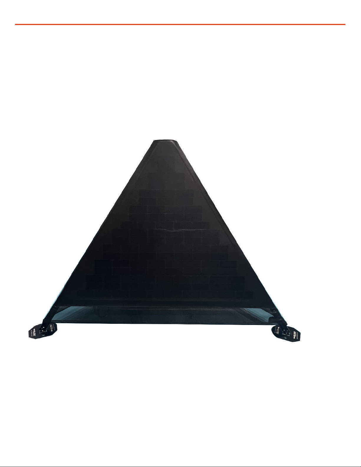
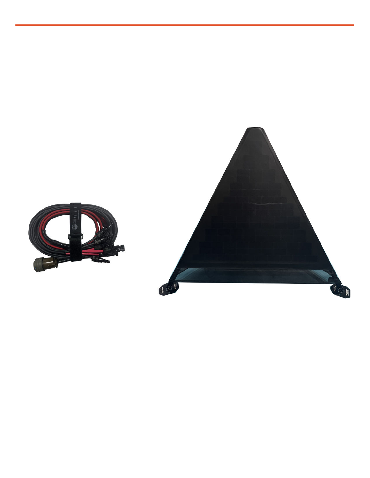
Figure 2. Solar Skirt
Solar Skirt Features:
• Thin-lm solar PV panels deliver maximum power generation with minimum weight
• Each panel is rated at 160 W, 8.4 A, 58 V at standard test conditions (STC), therefore power
generation is dependent on orientation
• Silent operation, minimal footprint, ease of use and low maintenance
P/N 11-100092
The Solar Skirt (Figure 2) has been specically tailored to provide a portable and silent DC power
generation source. The unique pyramidal design offers an innovative way of harvesting sunlight
throughout the day while working in tandem with PGA equipment.

October 2023 |Solar Stik®Inc.
12 |
Operator Manual for PGA Tour Power Module & Solar Skirt
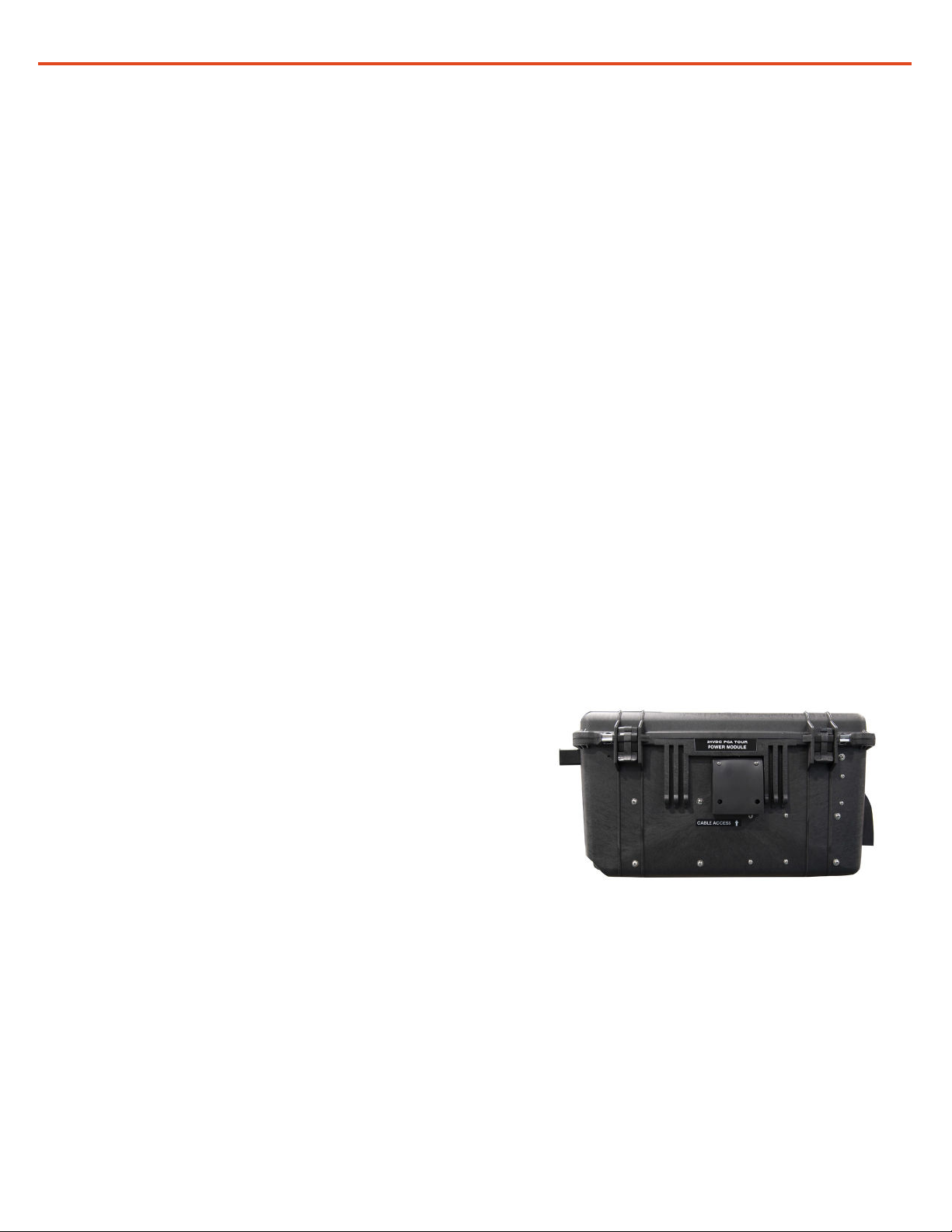
Cable Pass-through
Figure 3. 24VDC PGA Power Module (front)
Figure 4. 24VDC PGA Power Module (back)
Air Intake
Equipment Description

|13
October 2023 |Solar Stik®Inc.
Operator Manual for PGA Tour Power Module & Solar Skirt
Figure 6. Radar connector on (left), Solar connector on Solar Leash (middle) and Donor connector (right)
A(-)
B
C(+)
Pin A (-)
Pin C (+)
Pin B
unused
Air Exhaust Air Intake
Figure 7. 24VDC PGA Power Module (right side)
Figure 8. 24VDC PGA Power Module (left side)
2(-)
1(+)
B
Pin 2 (-)
Pins 1 (+)
B(-)
A(+)
Pin A (+)
Pins B (-)
24VDC
Inter-
Connect
Port
Figure 5. 24VDC PGA Power Module (back)
AC Input
Port
Donor
Output Port
Radar Ports
Air Intake
Solar/Donor Input
Port

October 2023 |Solar Stik®Inc.
14 |
Operator Manual for PGA Tour Power Module & Solar Skirt
Port/Connection Type of Port Nominal Voltage/Frequency Max Power Max Amp
Inter-Connect (x1) Input/Output 24 VDC 1200 W 50
Solar/Donor Input 48 VDC 600 W 30
USB C (x1) Output Only 5 VDC 15 W 3
Radars (x2) Output Only 22 VDC 200 W 10
Camera ports (x3):
Pan & Tilt
Switch
Output Only 22 VDC
52 VDC
110 W
240 W
5
15
Donor Output Output Only 48 VDC 600 W 40
Table 1. Power Module Ports Specications
|15
October 2023 |Solar Stik®Inc.
Operator Manual for PGA Tour Power Module & Solar Skirt
Figure 9. Solar Leash
SOLAR SKIRT SETUP AND OPERATION
It is recommended that the Solar Skirt be erected using two or more people. The Solar Skirt
(Figure 10) should be placed in an area that provides optimal sunlight throughout the day. The
Blue Sky Mast tripod is the frame on which to attach the Solar Skirt. Follow PGA guidelines for
erecting the Blue Sky Mast. Attach each individual panel to the mast using the Hook and Loop
strap located on each panel. Continue to attach the Solar Skirt by zipping the three panels
together. Connect the panel cables to the Solar Leash (Figure 9).
Figure 10. Solar Skirt

October 2023 |Solar Stik®Inc.
16 |
Operator Manual for PGA Tour Power Module & Solar Skirt
A. Specications Via QR Code
B. Battery Toggle Switch
C. Battery Breaker 50 A
D. USB A PI Console port exclusively used for data communication with Raspberry PI
E. USB C Accessory Power Only 5V, 3A
F. Cable Passthrough
G. Camera Connectors
H. E Display
I. Clear window for viewing internal communication operations
J. AP and Radar ports
K. Breaker Status LEDs
L. Fiber optic connectors
Faceplate
The Faceplate is found on the inside of the Power Module and provides information on the technical
specications and instructions for recharging, storage, and transport via a QR code. The Faceplate also
provides access to the E Display, system breakers, and necessary ports for PGA connections including
cameras and ber optics.
Figure 11. 24VDC PGA Tour Power Module Faceplate
H
A
BD
F
K
L
J
E
C
I
G

|17
October 2023 |Solar Stik®Inc.
Operator Manual for PGA Tour Power Module & Solar Skirt
The Power Module I-Plate provides setup and a quick-start guide for modes of operation. This guide is
located on the inside lid of the Power Module (Figure 11)
The Information Plate (I-Plate)
Figure 12. 24VDC PGA Tour Power Module I-Plate

October 2023 |Solar Stik®Inc.
18 |
Operator Manual for PGA Tour Power Module & Solar Skirt
Figure 13. Power ow from a top-down view of the interior of the Power Module
Theory of Operation
The Power Module combines power management and energy storage into a single, multi-faceted
platform for power. It employs a state-of-the-art lithium iron phosphate (LiFePO4) battery that stores up
to 1.44 kWh (60 Ah @ 24 V) of energy, and the battery is supported by distinct AC and DC circuits.
The Power Module can be charged by both conventional AC and DC sources, including renewable
energy, in order to maintain usable power on demand. Currently only DC loads are supported by the
Power Module.
Figure 13 illustrates the ow of power in the Power Module and the characteristics of the connector
ports.
1
3
Circuit Breakers
Numbers over breakers
correspond to numbered
breaker locations on
diagram above.
2
4
5
6
7
8
24 VDC LiFePO4
Battery
Solar/Donor
Input
5 VDC
USB C
Donor Output
DC/DC
Converter
Cameras
DC/DC
Converter
Radars
AC/DC
Battery
Charger
90-260
VAC,
60 Hz
DC/DC
Converter
24 VDC
Inter-Connect
Solar
Charge
Controller
1
23
4
5
7
8
6
AC input
Solar input
DC bus circuit
Circuit breaker location
LED Circuit activity indicator

|19
October 2023 |Solar Stik®Inc.
Operator Manual for PGA Tour Power Module & Solar Skirt
Modes of Operation
Loads
AC Power Harvesting
• Allows exible AC charging as necessary during periods of storage or when PV generation is
inadequate.
Uninterruptible Power Supply (UPS) Mode
• When PV generation is not an option.
• Allows connection of a generator or grid source for load support. Battery will serve as back-up
power for critical loads during interruptions in AC source supply.
Loads
Generator
Figure 15. Using the Power Module in Solar and AC Power Harvesting Mode
Figure 14. Using the Power Module in Autonomous Mode
Loads Solar
• Supports PGA sanctioned equipment including cameras and communications.
• Allows the Solar Skirt to serve as the primary power generation source. Requires abundant and
stable sunlight.
Grid
Figure 16. Using the Power Module in UPS Mode
Autonomous Mode
Load
Load
Grid
Load
AC
AC
Solar

October 2023 |Solar Stik®Inc.
20 |
Operator Manual for PGA Tour Power Module & Solar Skirt
Balanced Operation
When a load is connected to the Power Module, power is supplied immediately from the battery to
support it. The battery can store 1560 Wh of energy. Therefore, by itself, it can support a continuous load
for only a nite amount of time before needing to recharge.
There’s a simple rule that applies to using a battery as the primary source of power:
Power generated into the Power Module must be equal to or greater than the power consumed
by the load.
When the Power Module is connected to a power source, it should both recharge the battery AND
continue to power the load over a period of time.
Cycling the Battery
A battery cycle is dened as one complete discharge and recharge of the battery over a specic period
of time. In a cycling application, a proper balance between power generated and power consumed over
a 24-hour period will cycle the battery 1–2 times (on average).
The Power Module battery will cycle when it is used in Hybrid and Autonomous modes.
AC Circuits
Input/Charging
The Power Module battery can be charged using 90-260 VAC input. While the System can accept a
certain range of power, the universal input cable provided by Solar Stik is a 120 VAC locking cable and is
compatible with North American 120 V, 60 hz power.
DC Circuits
The Power Module has the following DC circuits:
• One (1) 24 VDC Inter-Connect port, 50 A: This port is used to connect to Power Modules together to
increase battery capacity.
• One (1) 48 VDC Donor Output, 40 A: This port provides connection between two Power Modules for
charging from the donor Power Module to the receiving Power Module.
• One (1) Solar/Donor Input, 100 VDC, 30 A: This port allows charging from the Solar Skirt or the donor
Power Module.
• Two (2) Radar cable ports, 22 VDC, 10 A: These ports supply power to PGA radars.
• Three (3) Camera connectors, 22 VDC, 5 A; 52 VDC 15 A: These connectors are located on the
Faceplate and are used to power PGA cameras.
• One (1) USB C port, 5 VDC, 3 A: This port is located on the Faceplate and supports small DC loads
to small devices
Table of contents
Other Solar Stik Batteries Pack manuals

Solar Stik
Solar Stik Li Expander Pak 2400 User manual

Solar Stik
Solar Stik BOS 2000-120-5199 User manual

Solar Stik
Solar Stik 24VDC Li ESM 2000 Installation instructions

Solar Stik
Solar Stik 24VDC LI BOS 500-120 User manual

Solar Stik
Solar Stik 24VDC LI EXPANDER PAK 1300 Installation instructions

Solar Stik
Solar Stik 24VDC POWER HUB 2400 Installation instructions

Solar Stik
Solar Stik PRO-VERTER Installation instructions


