SolarEdge RGM Operating instructions

Version 1.0
SolarEdge
Built-in Revenue
Grade Meter
Troubleshooting

Contents
Troubleshooting Meter Connection 3
Communication Status Screen Troubleshooting 3
Device Type and Protocol are configured incorrectly 3
Number of devices is not displayed 3
Meter Status Screen Troubleshooting 4
<OK> is not displayed 4
An error message is displayed 4
Total [Wh] value is not advancing 4
Replacing the Built-in Meter 6
Replacing the Meter 6
Wiring the Meter 6
Replacing the Safety Switch 10
Removing the Safety Switch 10
Installing a New Safety Switch 10
Connecting the Safety Switch to the Inverter 10
Connecting a Built-in Revenue Grade Meter 12
CAUTION!
For full installation and safety details, refer to the SolarEdge Installation Guide. Make sure you read, fully understand and follow the
detailed instructions in it prior to each installation. Failure to do so may result in injury or loss of life and damage to the equipment.
Built-in Revenue Grade Meter Troubleshooting
2

Troubleshooting Meter Connection
SolarEdge revenue grade inverters have a built in Revenue Grade Meter (RGM). This section describes how to troubleshoot meter-related
installation and performance errors.
Communication Status Screen Troubleshooting
The meter configuration is set automatically when activating the inverter using the activation card. The communication status screen should
display the following:
wwwwwwwwDevProt##
RS485-1<MTR><WN><1>
R S 4 8 5 - 2 < - - - > < - - > < - - >
Z i g B e e < - - - > < - - > < - - >
Device Type and Protocol are configured incorrectly
If MTR (meter) is not displayed as the device type (DEV), and WN (WattNode) is not displayed as the Prot (protocol), the inverter
preconfiguration has been overriden. This may be a result of inverter activation or communication board replacement without backing-up and
reloading the parameters.
Configure the meter as follows:
1. Select Communication è RS485-1 Conf è Device Type è Revenue Meter.
2. Select Communication è RS485-1 Conf è Protocol è WattNode.
3. Select Revenue Meter è Meter Func. è Production.
4. Check that the Device ID under Communication è RS485-1 Conf è Device ID is set to 1.
Number of devices is not displayed
If <--> is displayed under the ## column in the Communication status screen shown above, the meter is not communicating with the inverter.
Check the following:
lThe meter configuration is as described above.
lThere are no loose connections at the inverter connectors and at the meter, specifically the RS485 wiring.
Figure 1: Example of a loose meter connector
lThe wiring between the black 4-pin terminal block on the meter and the RS485 terminal block on the communication board is correct,
as shown below.
Figure 2: RS485 connection
Built-in Revenue Grade Meter Troubleshooting
3
Troubleshooting Meter Connection

lCheck for water damage or sealing problems:
oInspect the entire conduit run for possible points of water penetration, and fix leaks.
oEnsure that proper outdoor rated components are used.
oIn case of damaged equipment, replace either the meter or the Safety Switch, as described in the next sections.
lUse a Voltmeter to measure the voltage on the meter 10-pin terminal block . The L1 – L2 line to line voltage should be 240 Vac ± 10%.
Meter Status Screen Troubleshooting
RevenueGradeMeter
Status:<OK>
<ErrorMessage>
Total[Wh]:XXXXXXX
<OK> is not displayed
If <OK> is not displayed in the Status line of the status screen shown above, the meter is not communicating with the inverter
communication board. Check the following:
lThere are no loose connections at the inverter communication board and at the meter.
lThe wiring between the black 4-pin terminal block on the meter and the RS485 terminal block on the communication board is correct
(See Figure 2).
lCheck for water damage or sealing problems:
oInspect the entire conduit run for possible points of water penetration, and fix leaks.
oEnsure that proper outdoor rated components are used.
oIn case of damaged equipment, replace either the meter or the Safety Switch, as described in the next sections.
An error message is displayed
lIf Comm. Error is displayed, verify proper connection of:
oThe RS485 cables and connectors
oThe AC connection of the meter
lIf a different error message is displayed in the RGM status screen, contact SolarEdge support (support@solaredge.com).
Total [Wh] value is not advancing
If the Total [Wh] value displays a steady value although the inverter is producing power, check the following:
lThere are no loose connections at the inverter connectors and at the meter, specifically the AC wiring on the meter 10-pin connector.
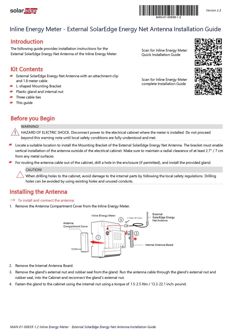
lThe CT black and white cables are correctly connected to the 6-pin connector on the meter:
oWhite CT wire is connected to L1 CT
oBlack CT wire is connected to L1 CT
lThe L1 cable passes through the CT in the correct direction (right to left), according to the arrow on the inside of the CT.
Figure 3: Meter Connections
Built-in Revenue Grade Meter Troubleshooting
4
Meter Status Screen Troubleshooting

Figure 4: Meter Connection diagram
lCheck for water damage or sealing problems:
oInspect the entire conduit run for possible points of water penetration, and fix leaks.
oEnsure that proper outdoor rated components are used.
oIn case of damaged equipment, replace either the meter or the Safety Switch, as described in the next sections.
Built-in Revenue Grade Meter Troubleshooting
5
Total [Wh] value is not advancing

Replacing the Built-in Meter
This section describes how to replace the meter in the Safety Switch, and how to configure the connection.
Replacing the Meter
1. Turn OFF the inverter ON/OFF switch, and wait until the LCD indicates that the DC voltage is safe (<50V), or wait five minutes before
continuing to the next step.
WARNING!
Ifyoucannotseetheinverterpanel,orifamalfunctionisindicatedontheLCDpanel,waitfiveminutesfortheinputcapacitorsofthe
invertertodischarge.
Si vous ne pouvez pas voir l'écran de l'onduleur ou si un dysfonctionnement est indiqué sur l'écran LCD, attendez cinq minutes pour que
les condensateurs d'entrée de l'onduleur soient déchargés.
2. Turn OFF the Safety Switch and the AC switch of the distribution panel.
3. Open the Safety Switch cover.
4. Carefully disconnect the three terminal blocks from the meter:
lGreen AC 10-pin connector from the right side
lBlack RS485 4-pin connector and black CT 6-pin connector from the left side
5. Release the two screws connecting the meter to the pivoting plate, and put them aside.
6. Install a new meter on the pivoting plate and fasten the screws that were set aside.
7. Connect the terminal blocks to the new meter. Push firmly and verify they cannot be easily disconnected.
Wiring the Meter
If required (for example, if you disconnected the meter wiring) use the following procedure to rewire the meter connections.
Refer to Figure 5.
Figure 5: RGM connections
Built-in Revenue Grade Meter Troubleshooting
6
Replacing the Built-in Meter

To connect the meter to AC:
1. Remove the green 10-pin terminal block from the right side of the meter.
2. Insert the thin cables from the AC side of the Safety Switch to the terminal block, as described below:
Color From To pin #
Green/Yellow GND 10
White N 8
Red L1 6
Black L2 4
3. Fasten the terminal block screws. Apply torque of 4.4 Lb*in (0.5 N*m).
4. Connect the terminal block to the to the meter. Push it firmly and verify that it cannot be easily disconnected.
Figure 6: 10-pin connections
To connect the Current Transformer (CT):
1. Remove the black 6-pin terminal block from the left side of the meter.
2. Insert the cables to the terminal block, as described below:
Color and type From To pin #
WhiteCTwire CT 1(L1CT)
BlackCTwire CT 2(L2CT)
Blackshortcable TerminalblockPin#1 3
Blackshortcable TerminalblockPin#5 6
3. Fasten the terminal block screws. Apply torque of 0.5 N*m (4.4 Lb*in).
Figure 7: CT connections
4. Connect the terminal block to the meter. Push it firmly and verify that it cannot be easily disconnected.
Built-in Revenue Grade Meter Troubleshooting
7
Wiring the Meter

5. If disconnected, insert the red thick cable from the L1 terminal on the AC side of the Safety Switch through the CT from right to left, and
through the AC conduit towards the inverter. The direction is indicated by the arrow on the CT.
NOTE
MakesurethattheonlycablepassingthroughtheCTistheonefromtheL1ACterminalblock.Othercablespassingthroughthe
CTmaycauseincorrectmeterreadings.
Figure 8: Wiring the L1 cable through the CT
To connect an RS485 communication cable:
1. Remove the black 4-pin terminal block from the left side of the meter.
2. Insert the cable wires to the terminal block, as described below:
Color and type To pin #
Yellow(B-) 1
Green(A+) 2
Black(G) 3
Figure 9: RS485 connection
3. Fasten the terminal block screws. Apply torque of 4.4 Lb*in (0.5 N*m).
4. Connect the terminal block to the meter. Push it firmly and verify that it cannot be easily disconnected.
5. Connect the other end of the cable to the SolarEdge inverter as detailed in Connecting a Built-in Revenue Grade Meter on page 12.
Built-in Revenue Grade Meter Troubleshooting
8
Wiring the Meter

6. Close the Safety Switch cover.
7. When the inverter is ON and operating, check the following:
lIn the Meter status screen:
o<S_OK> is displayed
oThe Total [Wh] value is advancing
oThere is no error messsage
RevenueGradeMeter
Status:<OK>
<ErrorMessage>
Total[Wh]:XXXXXXX
lIn the Communication status screen, the following configuration is displayed:
wwwwwwwwDevProt##
RS485-1<MTR><WN><1>
RS485-2<---><--><-->
Z i g B e e < - - - > < - - > < - - >
Built-in Revenue Grade Meter Troubleshooting
9
Wiring the Meter

Replacing the Safety Switch
Removing the Safety Switch
1. Turn OFF the inverter ON/OFF switch, and wait until the LCD indicates that the DC voltage is safe (<50V), or wait five minutes before
continuing to the next step.
WARNING!
Ifyoucannotseetheinverterpanel,orifamalfunctionisindicatedontheLCDpanel,waitfiveminutesfortheinputcapacitorsofthe
invertertodischarge.
Si vous ne pouvez pas voir l'écran de l'onduleur ou si un dysfonctionnement est indiqué sur l'écran LCD, attendez cinq minutes pour que
les condensateurs d'entrée de l'onduleur soient déchargés.
2. Turn OFF the Safety Switch and the AC switch of the distribution panel.
3. Open the inverter cover.
4. Disconnect the DC and AC wires from the inverter. If there are ferrite beads on the DC and AC wires in the inverter, open them and set
aside.
5. Disconnect the RS485 connector from the inverter communication board.
6. Unscrew the two conduit nuts in the inverter securing the Safety Switch to the inverter.
7. Open the Safety Switch cover and disconnect the DC and AC wires. Unscrew the two conduit nuts securing the Safety Switch to the
external conduits.
8. If the Safety Switch bracket is screwed to the wall, release it.
9. Carefully remove the Safety Switch with its mounting bracket and RGM communication cable from the wall.
Installing a New Safety Switch
1. Open the conduit knockouts of the new Safety Switch (refer to Opening Conduit Knockouts on page 1).
2. Position the new Safety Switch below the inverter and from the inside of the inverter grab the AC and DC wires extending from the switch
conduits, as shown below:
Figure 10: Inserting the AC and DC conduits
3. Attach the Safety Switch with its bracket to the wall and slightly close the screws. Do not over tighten.
4. Insert the RGM RS485 cable through the DC side conduit of the Safety Switch and connect to the inverter communication board.
5. Securely screw the two conduit nuts onto the conduit ends in the inverter. Verify proper conduit sealing.
Connecting the Safety Switch to the Inverter
1. If ferrite beads were removed from the DC and AC wires, place them on the wires and close them. Make sure the DC labeled ferrite bead
is placed on the DC wires and the AC labeled ferrite bead is placed on the AC wires.
2. Connect the DC, as follows:
lConnect the red wire to any of the DC+ terminals in the inverter.
lConnect the black wire to any of the DC- terminals in the inverter.
Built-in Revenue Grade Meter Troubleshooting
10
Replacing the Safety Switch

Figure 11: Single phase 3-7.6kW inverter DC terminals
Figure 12: Single phase 10-11.4 kW inverter DC terminals
3. Connect the AC wires according to the labels on the AC terminal blocks, as follows:
Single Phase Inverter
Wire color Connect to terminal
Figure 13: Single phase i nverter AC terminals
White N
Green/yellow Ground
Red L1
Black L2
4. Tighten the screws of each terminal with a torque of 0.88-1.1 lb.*ft / 1.2-1.5 N*m.
Built-in Revenue Grade Meter Troubleshooting
11
Connecting the Safety Switch to the Inverter
5. Connect the RS485 connector from the RGM to the inverter communication board.
6. Verify that there are no unconnected wires at the output of the Safety Switch and that any unused terminal screws are tightened.
7. Connect the DC and AC wires to the Safety Switch.
8. Ensure proper conduit sealing; inspect the entire conduit run and use standard conduit sealants to avoid water penetration.

Connecting a Built-in Revenue Grade Meter
1. Pull out the 9-pin RS485 terminal block connector located on the inverter communication board, as shown below:
Figure 16: The RS485 terminal block
2. Loosen the screws of pins A and B of the RS485-1 port, as shown below:
Figure 17: RS485 terminal block
3. Insert the wire ends from the meter into the pins shown above:
lConnect the wire from RS485 A+ in the meter to pin A.
lConnect the wire from RS485 B- in the meter to pin B.
lConnect the wire from RS485 G in the meter to pin G.
4. Tighten the terminal block screws.
5. Push the RS485 terminal block firmly all the way into the communication board.
Built-in Revenue Grade Meter Troubleshooting
12
Connecting a Built-in Revenue Grade Meter
Table of contents
Other SolarEdge Measuring Instrument manuals
SolarEdge
SolarEdge AS4034-1 User manual
SolarEdge
SolarEdge SE-MTR240-NN-S-S1 User manual
SolarEdge
SolarEdge SE-MTR-3Y-400V-A User manual
SolarEdge
SolarEdge SE-WND-3Y400-MB-K2 User manual
SolarEdge
SolarEdge SE-RGMTR-3D-208V-A User manual

SolarEdge
SolarEdge SE330K Installation and operating instructions
SolarEdge
SolarEdge MTR-240-3PC1-D-A-MW User manual
SolarEdge
SolarEdge SolarEdge SE-MTR240-2-400-S1 User manual
