SolarEdge SE-RGMTR-3D-208V-A User manual

Installation Guide
Revenue Grade Energy Meter
with Modbus Connection
For North America
Version 1.0

Disclaimers
Important Notice
Copyright © SolarEdge Inc. All rights reserved.
No part of this document may be reproduced, stored in a
retrieval system or transmitted, in any form or by any means,
electronic, mechanical, photographic, magnetic or otherwise,
without the prior written permission of SolarEdge Inc.
The material furnished in this document is believed to be
accurate and reliable. However, SolarEdge assumes no
responsibility for the use of this material. SolarEdge reserves
the right to make changes to the material at any time and
without notice. You may refer to the SolarEdge web site
(https://www.solaredge.com/us/) for the most updated
version.
All company and brand products and service names are
trademarks or registered trademarks of their respective holders.
Patent marking notice: see
https://www.solaredge.com/us/patent
The general terms and conditions of delivery of SolarEdge shall
apply.
Revenue Grade Energy Meter with Modbus Connection Installation Guide MAN-01-00609-1.0
Disclaimers1

The content of these documents is continually reviewed and
amended, where necessary. However, discrepancies cannot be
excluded. No guarantee is made for the completeness of these
documents.
The images contained in this document are for illustrative
purposes only and may vary depending on product models.
FCC Compliance
This equipment has been tested and found to comply with the
limits for a Class B digital device, pursuant to part 15 of the FCC
Rules.
These limits are designed to provide reasonable protection
against harmful interference in a residential installation. This
equipment generates, uses and can radiate radio frequency
energy and, if not installed and used in accordance with the
instructions, may cause harmful interference to radio
communications. However, there is no guarantee that
interference will not occur in a particular installation. If this
equipment does cause harmful interference to radio or
television reception, which can be determined by turning the
equipment off and on, you are encouraged to try to correct
the interference by one or more of the following measures:
Revenue Grade Energy Meter with Modbus Connection Installation Guide MAN-01-00609-1.0
2 FCC Compliance
Reorient or relocate the receiving antenna.
Increase the separation between the equipment and the
receiver.
Connect the equipment into an outlet on a circuit different
from that to which the receiver is connected.
Consult the dealer or an experienced radio/TV technician
for help.
Changes or modifications not expressly approved by the party
responsible for compliance may void the user’s authority to
operate the equipment.
Version History
Version 1.0 (July 2019) - Initial release
Revenue Grade Energy Meter with Modbus Connection Installation Guide MAN-01-00609-1.0
Disclaimers3

Support and Contact Information
If you have technical problems concerning SolarEdge
products, please contact us:
USA and Canada: 1 510 498 3200
Worldwide: +972 073 2403118
Fax: +1 (530) 273-2769
Email: ussupport@solaredge.com.
Support Center:
https://www.solaredge.com/us/service/support
Revenue Grade Energy Meter with Modbus Connection Installation Guide MAN-01-00609-1.0
4 Support and Contact Information

Before contact, make sure to have the following information at
hand:
Model and serial number of the product in question.
The error indicated on the Revenue Grade Energy Meter
with Modbus Connection SetApp mobile application LCD
screen or on the monitoring platform or by the LEDs, if
there is such an indication.
System configuration information, including the type and
number of modules connected and the number and
length of strings.
The communication method to the SolarEdge server, if the
site is connected.
The Revenue Grade Energy Meter with Modbus
Connection software version as appears in the ID status
screen.
Revenue Grade Energy Meter with Modbus Connection Installation Guide MAN-01-00609-1.0
Support and Contact Information5
Contents
Disclaimers 1
Important Notice 1
FCC Compliance 2
Support and Contact Information 4
Contents 6
HANDLING AND SAFETY INSTRUCTIONS 8
Safety Symbols Information 8
Chapter 1: Introduction 10
Terminology 10
The SolarEdge Revenue Grade Energy Meter with
Modbus Connection 12
Meter Connection Options 13
Meter Interfaces 15
Chapter 2: Meter Installation 19
Installation Guidelines 19
Installing and Connecting the Meter 20
Chapter 3: Configuration 28
SolarEdge Device Firmware Version 28
Device Configuration 31
Appendix A: Troubleshooting the Meter 45
Troubleshooting the Meter using SetApp 45
Troubleshooting the Meter using the Device Display 50
Appendix B: Installing Two Meters 55
Revenue Grade Energy Meter with Modbus Connection Installation Guide MAN-01-00609-1.0
6 Contents
Connecting Two Meters 55
Configuring the Dual-Meter Connection 57
Verifying Meter Connection 62
Troubleshooting Dual-Meter Connection 64
Appendix C: Monitoring Platform - Meter Data 66
Appendix D: External Lightning Protection 68
Revenue Grade Energy Meter with Modbus Connection Installation Guide MAN-01-00609-1.0
Contents7
HANDLING AND SAFETY
INSTRUCTIONS
During installation, testing and inspection, adherence to all the
handling and safety instructions is mandatory. Failure to do so
may result in injury or loss of life and damage to the
equipment.
Safety Symbols Information
The following safety symbols are used in this document.
Familiarize yourself with the symbols and their meaning before
installing or operating the system.
WARNING!
Denotes a hazard. It calls attention to a procedure
that, if not correctly performed or adhered to, could
result in injury or loss of life. Do not proceed beyond a
warning note until the indicated conditions are fully
understood and met.
AVERTISSEMENT!
Dénote un risque: il attire l'attention sur une opération
qui, si elle n'est pas faite ou suivi correctement,
pourrait causer des blessures ou un danger de mort.
Ne pas dépasser une telle note avant que les
conditions requises soient totallement comprises et
accomplies.
Revenue Grade Energy Meter with Modbus Connection Installation Guide MAN-01-00609-1.0
8 HANDLING AND SAFETY INSTRUCTIONS

CAUTION!
Denotes a hazard. It calls attention to a procedure
that, if not correctly performed or adhered to, could
result in damage or destruction of the product. Do
not proceed beyond a caution sign until the indicated
conditions are fully understood and met.
ATTENTION!
Dénote un risque: il attire l'attention sur une opération
qui, si elle n'est pas faite ou suivi correctement,
pourrait causer un dommage ou destruction de
l'équipement. Ne pas dépasser une telle note avant
que les conditions requises soient totallement
comprises et accomplies.
NOTE
Denotes additional information about the current
subject.
IMPORTANTSAFETYFEATURE
Denotes information about safety issues.
Revenue Grade Energy Meter with Modbus Connection Installation Guide MAN-01-00609-1.0
HANDLING AND SAFETY INSTRUCTIONS9

Chapter 1: Introduction
Terminology
The following terms are used in this document:
Export: The power injected to the grid.
Import: The power purchased from the grid.
Export/Import meter: A meter that is installed at the grid
connection point and measures the energy/power
exported/imported to/from the grid.
Consumption: The power consumed by the site.
Consumption meter: A meter that is installed at the load
consumption point and measures the energy/power
consumed by the site.
Self-consumption: The PVpower consumed by the site
and not fed into the grid.
Production: The power produced by the PV system.
Production meter: A meter that is installed at the inverter
output or site AC connection, or in the inverter (a built-in
revenue grade meter), and measures the energy/power
produced by the PVsystem or site.
Revenue Grade Energy Meter with Modbus Connection Installation Guide MAN-01-00609-1.0
10 Chapter 1: Introduction
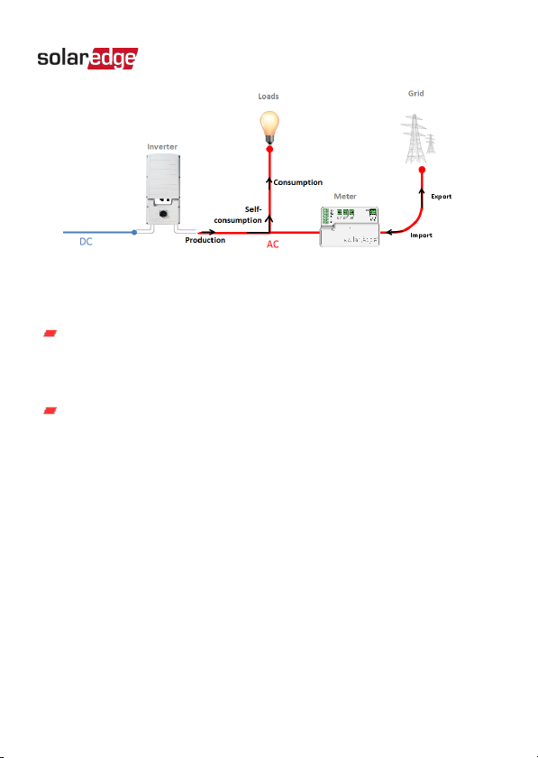
Figure 1: Terminology Illustration
Three-phase grid configuration types:
Wye: In a Wye ("Y") configuration, all three phases are
connected at a single neutral point. Wye systems utilize
five wires - three hot, one neutral and one ground.
Delta: In a Delta configuration, the three phases are
connected in a triangle. Delta systems utilize four wires -
three hot and one ground.
Revenue Grade Energy Meter with Modbus Connection Installation Guide MAN-01-00609-1.0
Chapter 1: Introduction11

The SolarEdge Revenue Grade Energy
Meter with Modbus Connection
The SolarEdge Revenue Grade Energy Meter with Modbus
Connection (also referred to as “the meter”) enables measuring
the power and energy of the photovoltaic (PV)system.
The following meter models are available:
SolarEdge Meter Model Grid Type
SE-RGMTR-3D-208V-A Delta
SE-RGMTR-3Y-208V-A Wye
SE-RGMTR-3Y-480V-A Wye
The meter is used by the inverter for the following applications:
Production metering
Consumption monitoring
Export limitation
Smart Energy on-grid applications
The meter requires
three Current Transformers
(CTs). The CTs
are available from SolarEdge.
The SolarEdge inverter or the Commercial Gateway (CCG) reads
the exported/imported power from a meter installed at the grid
connection point or reads the consumption from a meter
installed at the load consumption point.
Revenue Grade Energy Meter with Modbus Connection Installation Guide MAN-01-00609-1.0
12 The SolarEdge Revenue Grade Energy Meter with
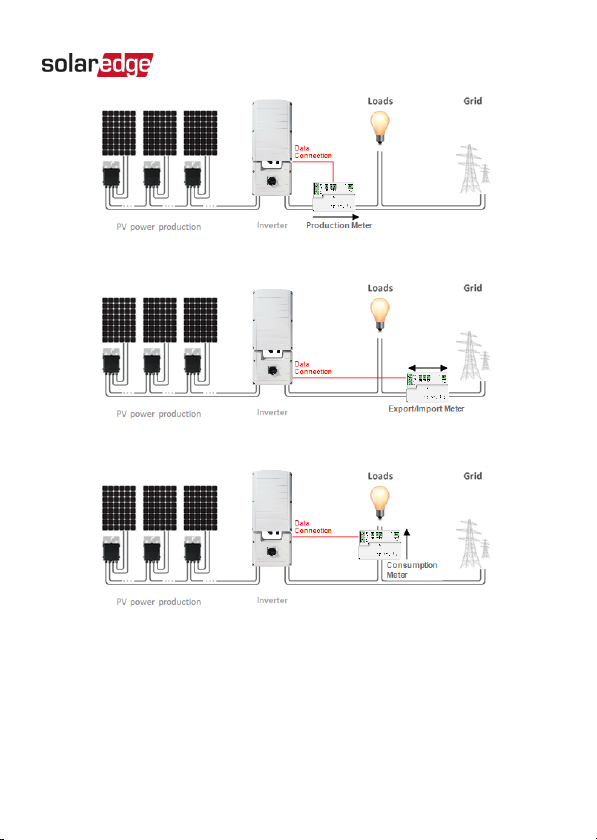
Figure 2: Typical installation with production meter
Figure 3: Typical installation with export/import meter
Figure 4: Typical installation with consumption meter
Meter Connection Options
In a
single
inverter system, the meter is connected directly to
the inverter.
Revenue Grade Energy Meter with Modbus Connection Installation Guide MAN-01-00609-1.0
Chapter 1: Introduction13

Figure 5: Single-inverter connection
In a
multiple
inverter system, two options are available:
The meter is connected to an RS485 port of one of the
inverters.
If the inverter has a second RS485 port, use this port to
connect between the inverters.
If the inverter has only one RS485 port, use an RS485
Plug-In (available from SolarEdge) or ZigBee
communication between the inverters.
The meter is connected to one of the RS485 ports of a CCG.
The CCG’s second RS485 port can be used to create an
RS485 bus for communication between the inverters. This
option is illustrated in
Figure 6
.
Revenue Grade Energy Meter with Modbus Connection Installation Guide MAN-01-00609-1.0
14 Meter Connection Options

Figure 6: Multi-inverter connection with CCG and meter
Meter Interfaces
This section describes the SolarEdge meter's interfaces.
Figure 7: Delta (left) and Wye (right) Meter Interfaces
Voltage connections: for connection to the grid
Delta: L1, L2, L3, Ground
Wye: L1, L2, L3, N, Ground
CTconnections (L1 CT, L2 CT, L3 CT): for connection to
current transformers
RS485: for connection to the inverter/gateway
Revenue Grade Energy Meter with Modbus Connection Installation Guide MAN-01-00609-1.0
Chapter 1: Introduction15

LEDs: used to monitor meter status.
ID DIPswitches (ID 1, 2, 3): used to set the Modbus
address.
Termination DIPswitches (TERM 1, 2): used to set RS485
termination.
LEDs
The meter utilizes the LEDs at the top of the unit in order to
indicate current status.
Figure 8: Meter LED
Revenue Grade Energy Meter with Modbus Connection Installation Guide MAN-01-00609-1.0
16 Meter Interfaces
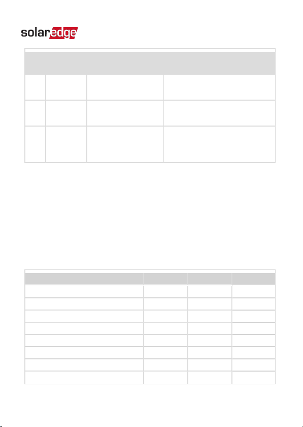
LED
#LED Function Indication
1Bottom -
green
Operational
status
Flashing ON/OFF - normal
operation
2Middle -
yellow
RS485 Modbus
communication
Flashing ON/OFF -
communication OK
3Top -
yellow
Energy
management
Turns ON when the meter
reads an energy change of
~1 kwH. Then turns OFF.
DIPSwitches
ID DIPSwitches
The IDDIPswitches are used to set the Modbus address of the
meter. The addressing options are listed in the table below. See
the figure
ID and Termination DIP Switches
on page 18 for
switch direction guidelines.
Modbus Address ID 1 ID 2 ID 3
0 Down Down Down
1 Up Down Down
2 Down Up Down
3 Up Up Down
4 Down Down Up
5 Up Down Up
6 Down Up Up
7 Up Up Up
Revenue Grade Energy Meter with Modbus Connection Installation Guide MAN-01-00609-1.0
Chapter 1: Introduction17
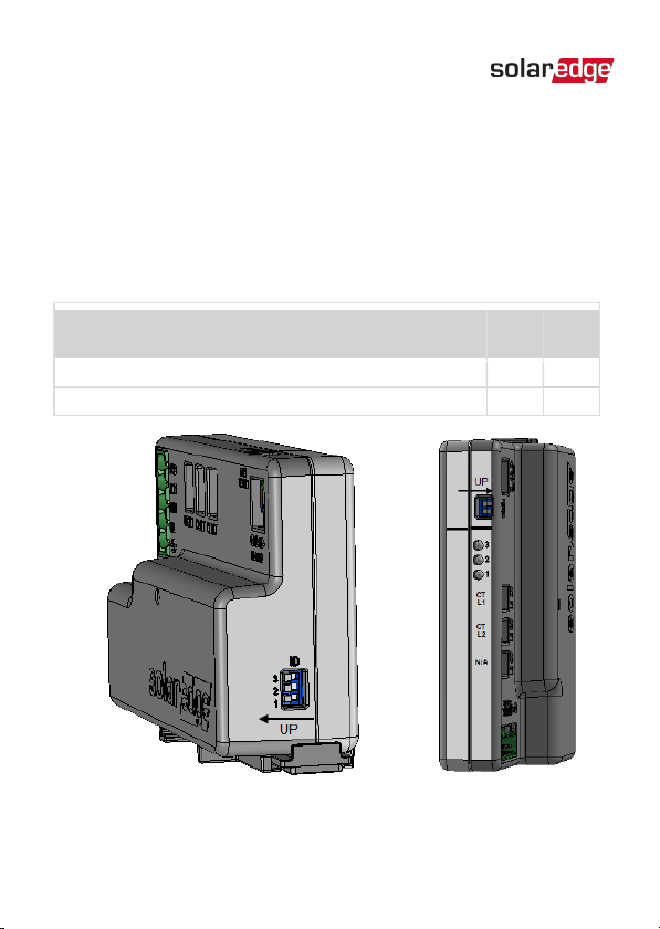
Termination DIPSwitches
The Termination DIPswitches are used to configure RS485
wiring termination. The termination options are listed in the
table below. See the figure
ID and Termination DIP Switches
on
page 18 for switch direction guidelines.
RS485 Termination TERM
1
TERM
2
Terminated Down Down
Not Terminated (factory default) Up Up
Figure 9: ID and Termination DIP Switches
Revenue Grade Energy Meter with Modbus Connection Installation Guide MAN-01-00609-1.0
18 Meter Interfaces
Chapter 2: Meter Installation
Installation Guidelines
AC wire specifications: 1.3 to 2.0 mm diameter / 16 to 12 AWG
stranded wire, 600 V, type THHN, MTW, or THWN.
RS485 wiring specifications:
Cable type: Min. 3-wire shielded twisted pair (a 4-wire
cable may be used)
Wire cross-section area: 0.2- 1 mm²/ 24-18 AWG (a CAT5
cable may be used)
NOTE
If using a cable longer than 10 m/33 ft in areas where
there is a risk of induced voltage surges by lightning,
it is recommend to use external surge protection
devices. For details refer to
External Lightning
Protection
on page 68. If grounded metal conduit are
used for routing the communication wires, there is no
need for a lightning protection device.
The meter is considered “permanently connected
equipment” and requires a disconnect means (circuit
breaker, switch, or disconnect) and overcurrent protection
(fuse or circuit breaker).
Revenue Grade Energy Meter with Modbus Connection Installation Guide MAN-01-00609-1.0
Chapter 2: Meter Installation 19
This manual suits for next models
2
Table of contents
Other SolarEdge Measuring Instrument manuals

SolarEdge
SolarEdge SE-MTR240-NN-S-S1 User manual

SolarEdge
SolarEdge SolarEdge SE-MTR240-2-400-S1 User manual

SolarEdge
SolarEdge SE330K Installation and operating instructions

SolarEdge
SolarEdge AS4034-1 User manual

SolarEdge
SolarEdge SE-MTR-3Y-400V-A User manual

SolarEdge
SolarEdge RGM Operating instructions

SolarEdge
SolarEdge SE-WND-3Y400-MB-K2 User manual

SolarEdge
SolarEdge MTR-240-3PC1-D-A-MW User manual


