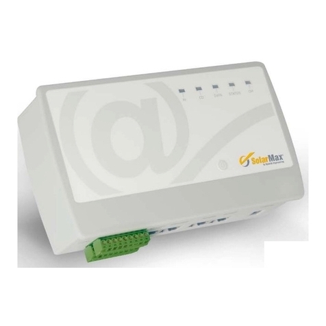
SolarMax MaxWeb XPN User manual

Installation instructions
MaxWeb XPN

3
en
Contents
1 About this installation manual � � � � � � � � � � � � � � � � � � � � � � � � � � � � � � � � � � � � � � 5
1.1 Scope. . . . . . . . . . . . . . . . . . . . . . . . . . . . . . . . . . . . . . . . . . . . . . . . . . . . . . 5
1.2 Where to keep this manual . . . . . . . . . . . . . . . . . . . . . . . . . . . . . . . . . . . . . . 5
1.3 Symbols used. . . . . . . . . . . . . . . . . . . . . . . . . . . . . . . . . . . . . . . . . . . . . . . . 5
2 Safety � � � � � � � � � � � � � � � � � � � � � � � � � � � � � � � � � � � � � � � � � � � � � � � � � � � � � � � � � � 6
2.1 Appropriate use . . . . . . . . . . . . . . . . . . . . . . . . . . . . . . . . . . . . . . . . . . . . . . 6
2.2 Safety instructions . . . . . . . . . . . . . . . . . . . . . . . . . . . . . . . . . . . . . . . . . . . . 6
2.3 Symbols used. . . . . . . . . . . . . . . . . . . . . . . . . . . . . . . . . . . . . . . . . . . . . . . . 6
3 Description � � � � � � � � � � � � � � � � � � � � � � � � � � � � � � � � � � � � � � � � � � � � � � � � � � � � � � 7
3.1 Function . . . . . . . . . . . . . . . . . . . . . . . . . . . . . . . . . . . . . . . . . . . . . . . . . . . . 7
3.2 Connections . . . . . . . . . . . . . . . . . . . . . . . . . . . . . . . . . . . . . . . . . . . . . . . . 10
3.3 Displays . . . . . . . . . . . . . . . . . . . . . . . . . . . . . . . . . . . . . . . . . . . . . . . . . . . .12
3.3.1 Status indicators . . . . . . . . . . . . . . . . . . . . . . . . . . . . . . . . . . . . . . .12
3.3.2 LCD display . . . . . . . . . . . . . . . . . . . . . . . . . . . . . . . . . . . . . . . . . . .12
3.3.3 Navigation keys. . . . . . . . . . . . . . . . . . . . . . . . . . . . . . . . . . . . . . . .15
3.4 External WLAN antenna . . . . . . . . . . . . . . . . . . . . . . . . . . . . . . . . . . . . . . . .15
4 Installation � � � � � � � � � � � � � � � � � � � � � � � � � � � � � � � � � � � � � � � � � � � � � � � � � � � � � 16
4.1 Transport and storage of the data logger . . . . . . . . . . . . . . . . . . . . . . . . . . 16
4.2 Scope of delivery . . . . . . . . . . . . . . . . . . . . . . . . . . . . . . . . . . . . . . . . . . . . 16
4.3 Siting . . . . . . . . . . . . . . . . . . . . . . . . . . . . . . . . . . . . . . . . . . . . . . . . . . . . . 16
4.4 Device installation . . . . . . . . . . . . . . . . . . . . . . . . . . . . . . . . . . . . . . . . . . . 16
5 Installation of the MaxComm network � � � � � � � � � � � � � � � � � � � � � � � � � � � � � � � �17
5.1 Connection options. . . . . . . . . . . . . . . . . . . . . . . . . . . . . . . . . . . . . . . . . . . .17
5.2 Connecting the inverters via the RS485 interface. . . . . . . . . . . . . . . . . . . . .17
5.3 Connecting the inverters via the Ethernet interface . . . . . . . . . . . . . . . . . . .18
5.4 Addressing . . . . . . . . . . . . . . . . . . . . . . . . . . . . . . . . . . . . . . . . . . . . . . . . . .19
5.5 Power supply . . . . . . . . . . . . . . . . . . . . . . . . . . . . . . . . . . . . . . . . . . . . . . . .19
6 Conguring the MaxWeb XPN � � � � � � � � � � � � � � � � � � � � � � � � � � � � � � � � � � � � � � 20
6.1 Switching on and off . . . . . . . . . . . . . . . . . . . . . . . . . . . . . . . . . . . . . . . . . 20
6.2 Network settings . . . . . . . . . . . . . . . . . . . . . . . . . . . . . . . . . . . . . . . . . . . . 20
6.3 Login to the MaxWeb XPN. . . . . . . . . . . . . . . . . . . . . . . . . . . . . . . . . . . . . . 22
6.4 Setting the language . . . . . . . . . . . . . . . . . . . . . . . . . . . . . . . . . . . . . . . . . 23
6.5 Registering for the MaxWeb Portal . . . . . . . . . . . . . . . . . . . . . . . . . . . . . . . 24
6.5.1 Network settings. . . . . . . . . . . . . . . . . . . . . . . . . . . . . . . . . . . . . . 24
6.5.2 System settings . . . . . . . . . . . . . . . . . . . . . . . . . . . . . . . . . . . . . . 28
6.5.3 Device search . . . . . . . . . . . . . . . . . . . . . . . . . . . . . . . . . . . . . . . . 29

4
6.5.4 Device settings . . . . . . . . . . . . . . . . . . . . . . . . . . . . . . . . . . . . . . . 33
6.5.5 Alarm settings. . . . . . . . . . . . . . . . . . . . . . . . . . . . . . . . . . . . . . . . 36
6.6 Registering for the MaxWeb Portal . . . . . . . . . . . . . . . . . . . . . . . . . . . . . . . 38
7 Monitoring the PV plant � � � � � � � � � � � � � � � � � � � � � � � � � � � � � � � � � � � � � � � � � � � 39
7.1 Opening the MaxWeb XPN user interface . . . . . . . . . . . . . . . . . . . . . . . . . . 39
7.2 User interface of the MaxWeb XPN . . . . . . . . . . . . . . . . . . . . . . . . . . . . . . . 39
7.2.1 Home . . . . . . . . . . . . . . . . . . . . . . . . . . . . . . . . . . . . . . . . . . . . . . 39
7.2.2 Plant / Logging. . . . . . . . . . . . . . . . . . . . . . . . . . . . . . . . . . . . . . . . 40
7.2.3 Energy. . . . . . . . . . . . . . . . . . . . . . . . . . . . . . . . . . . . . . . . . . . . . . 44
7.2.4 Alarms . . . . . . . . . . . . . . . . . . . . . . . . . . . . . . . . . . . . . . . . . . . . . 48
7.2.5 Devices . . . . . . . . . . . . . . . . . . . . . . . . . . . . . . . . . . . . . . . . . . . . . 49
7.2.6 Basic settings . . . . . . . . . . . . . . . . . . . . . . . . . . . . . . . . . . . . . . . . 58
7.2.7 Help . . . . . . . . . . . . . . . . . . . . . . . . . . . . . . . . . . . . . . . . . . . . . . . 62
7.2.8 Setup wizard. . . . . . . . . . . . . . . . . . . . . . . . . . . . . . . . . . . . . . . . . 63
8 Connection of external sensors and alarm systems � � � � � � � � � � � � � � � � � � � � 64
8.1 Connection options. . . . . . . . . . . . . . . . . . . . . . . . . . . . . . . . . . . . . . . . . . . 64
8.2 Irradiance and temperature sensor. . . . . . . . . . . . . . . . . . . . . . . . . . . . . . . 64
8.3 Conguration . . . . . . . . . . . . . . . . . . . . . . . . . . . . . . . . . . . . . . . . . . . . . . . 65
8.4 Inputs for external alarm sensors . . . . . . . . . . . . . . . . . . . . . . . . . . . . . . . . 65
8.5 Terminal assignment . . . . . . . . . . . . . . . . . . . . . . . . . . . . . . . . . . . . . . . . . 65
8.5.1 Terminal assignment on the front of the MaxWeb XPN . . . . . . . . . 65
8.5.2 Terminal assignment on the back of the MaxWeb XPN . . . . . . . . . 68
9 Troubleshooting � � � � � � � � � � � � � � � � � � � � � � � � � � � � � � � � � � � � � � � � � � � � � � � � � 70
10 Technical data � � � � � � � � � � � � � � � � � � � � � � � � � � � � � � � � � � � � � � � � � � � � � � � � � � 71
11 Disposal� � � � � � � � � � � � � � � � � � � � � � � � � � � � � � � � � � � � � � � � � � � � � � � � � � � � � � � � 71
12 Warranty � � � � � � � � � � � � � � � � � � � � � � � � � � � � � � � � � � � � � � � � � � � � � � � � � � � � � � � 72

5
en
1 About this installation manual
This installation guide describes the installation, the start-up and the functions of the
MaxComm accessory component MaxWeb XPN. SolarMax Produktions GmbH declines
any liability in the event of non-observance of the installation instructions.
1�1 Scope
This installation manual applies to the MaxWeb XPN data logger.
1�2 Where to keep this manual
The system operator must ensure that this instruction manual is available to those
responsible for the power plant at all times. If the original manual is lost, an up-to-date
version can be downloaded from our website at all times (www.solarmax.com).
1�3 Symbols used
The following safety instructions and general information are used within this instruction
manual:
DANGER!
Non-observance of these safety instructions may immediately cause serious
injuries or death.
WARNING!
Non-observance of these safety instructions may cause serious injuries.
ATTENTION!
Non-observance of these safety instructions may cause material damage.
Note
Notes contain extended information or facilitate the data logger operation.

6
2 Safety
2�1 Appropriate use
The web-based MaxWeb XPN data logger is solely for the logging of device and plant data
within a MaxComm communications network. MaxWeb XPN provides the following basic
functions:
Internet-capable data logger for system communication via standard Internet
browser
Automatic data transfer to the MaxWeb Portal and three further email recipients
Permanent system monitoring
Automatic alarms via email to up to three recipients
Up to 249 devices can be connected via RS485 interface
Communication via Ethernet, RS485, CAN bus, USB
2�2 Safety instructions
DANGER!
Fatal electric shock hazard!
Never open the plug-in power supply unit. Components within the plug-in
power supply unit are charged with a high voltage.
ATTENTION!
Risk of damage to the device!
Only SolarMax devices with RS485-type interfaces may be connected to
RS485 sockets. The interface carries active signals!
2�3 Symbols used
The following symbols can be found on the switching power supply of the device:
This product must not be disposed of with normal domestic waste�
CE mark
(Declaration of conformance with EEC-Guidelines)

7
en
Protective insulation: Class II equipment
This device is designed for indoor operation (dry environment)�
3 Description
3�1 Function
Fig. 1: MaxWeb XPN

8
Overview
The MaxWeb XPN has been developed for energy management by the SolarMax group.
As an intersection of the location-independent monitoring, it captures current measure-
ment values, yield data and events. As an energy management centre, it regulates the
energy ow and adjusts the energy demand to the availability. This allows for an intelli-
gent use of the resources.
Any obtained or delivered output is visualised and internal consumption as well as saved
current are represented in a graph. The software of the MaxWeb XPN is self-learning.
On the basis of the typical consumption and the weather forecast, the data logger will
determine the optimal time for storage of solar power, which increases efciency and
maximises returns.
MaxWeb XPN Features
The MaxWeb XPN has the following features:
MaxWeb XPN is downward compatible as it is based on MaxWeb xp.
MaxWeb XPN is suitable for MaxRemote, i.e. the network operator has the possibility
to remotely reduce the effective power of his PV plant temporarily in order to prevent
an overload of the power grid.
MaxWeb XPN is equipped with integrated WLAN, an internal WLAN antenna is
included within the scope of delivery.
MaxWeb XPN has a Modbus TCP interface for direct connection/control for direct
sellers.
MaxWeb XPN has 8 digital inputs, 4 digital outputs, 4 analogue inputs and one RS485
interface.
With the two S0 counter inputs of MaxWeb XPN, you can record the load prole and
determine the energy ow for energy management.
MaxWeb XPN is located in a standard prole rail housing with a two-line LCD display
on which important information can be displayed for a quick overview and requested
by using the navigation keys.
MaxWeb XPN is operated via an intuitive user guidance. This web interface can be
called up and operated comfortably from a PC as well as from mobile devices (smart-
phone, tablet).
MaxWeb XPN has a device replacement function. In case the MaxWeb XPN needs to
be replaced, the replacement device congures in a time-saving and nearly autono-
mous way to the last state of the replaced device without the need for a complete
reconguration.
MaxWeb XPN is an energy management centre which is used to manage the energy
ow of a complex plant. Various systems, devices and battery systems can be con-
nected, monitored and controlled via the different interfaces (Ethernet, Modbus,
RS485, KNX, CAN-Bus, etc.).

9
en
MaxWeb XPN has interfaces which can receive or implement control commands from
external devices or instances.
Using MaxWeb XPN, the demand for energy can be intelligently adapted to the avail-
ability. In this way, the available resources can be used intelligently.
Optional Modules for MaxWeb XPN
The basic components of the MaxWeb XPN can be extended with optional modules by the
internal CAN bus. The following optional modules can be added.
MaxModul KNX – module for implementation into the existing home automation to
increase the proportion of own consumption
User-specic modules – due to the modular design, it is possible to add custom-
er-specic developments in line with the demands of the customers.

10
3�2 Connections
Front
Fig. 2: Connections on the front of the MaxWeb XPN
Port Purpose
S0 pulse Pulse inputs for counting energy (see Section 8.5.1)
CAN bus Connection for CAN bus systems (see Section 8.5.1)
8 analogue inputs Connection for irradiance and temperature sensors (see Section 8.5.1)
RS485 RJ45 sockets for connecting the MaxComm network cable, galvani-
cally isolated
USB Type-A USB socket for connecting USB ash drives, hard disc drives,
notebook, etc.
Ethernet RJ45 socket for the Ethernet connection cable 10/ 100 Mbit/s

11
en
Rear
Fig. 3: Connections on the rear of the MaxWeb XPN
Port Purpose
Memory card
(microSD)
External microSD card for the storage of les
Power supply Jack socket for connecting a power supply unit with a supply voltage
of 15 … 24 V, 1.5 A
Digital inputs 8 digital inputs (see Section 8.5.2)
Relay outputs 4 relay outputs for switching e.g. in the event of inverter faults
(see Section 8.5.2)

12
3�3 Displays
3�3�1 Status indicators
The LEDs indicate the operational status of the device. As soon as the device is supplied
with power, the LEDs are ashing until the internal functions are checked; the ON LED
then lights continuously.
ON ON ON
cont. light When the device is ready for operation
STATUS STATUS STATUS
off During normal operation
WLAN off WLAN is inactive, no WLAN connection
cont. light When the device is connected to the WLAN
3�3�2 LCD display
The device features a two-line LCD display that shows important information and the
status of the plant.
As soon as the device is supplied with power, the MaxWeb XPN is switched on automati-
cally. During start-up, the LCD display shows the message “booting”. Once the message
“OK” appears in the LCD display, the MaxWeb XPN is ready for operation.
In this menu, you can change the basic settings, such as the selected language, execute
basic functions and check operating functions using the navigation keys.
Note
Via the LCD display, only basic settings can be made. The full scope of func-
tions of the MaxWeb XPN can only be used via the web browser.

13
en
Menu structure of the LCD display
The following menus can be selected via the LCD display:
!"#$%&
(%)*+%',"-% '"#$%#!&'()#*
./01"2%'.*, ''"+,-.+!/*
3%4*"0',5-&%4 '"+012,345*
3/617
"4%')%48*/,'"+-.-.*'"#$%#)
9:';1<%4,%1 '"+60-+35-0-+..*
9:'$=>? '"+60-+35-+-11*
:0",1'81"158
"7'()#!89*
!"#$%&'*,6/
@:?'8A81%-
./01"2%'.++ ''"1-10!/*
./01"2%'.&56 ''"2-56!/*
./01"2%'./51 ''",-.+!/*
3</7'@:?'9BC
>,"0/25%'*,D51'E'"+0-0!:;*
>,"0/25%'*,D51'F'"+2-+!:;*
>,"0/25%'*,D51'G'"+6-6!:;*
>,"0/25%'*,D51'H'",-00!:;*
(*2*1"0'*,D51 '"+.+..+*
(*2*1"0'/51D51 '"+.+*
I%81"41'@:?
37*1+<'/66'@:?
3%1'&"8*+')"05%8
3%0%+1
J%4-",
;,20*8<
91"0*",
K4%,+<
3D",*8<
:/0*8<
Fig. 4: Menu tree of the LCD display

14
Operation of the LCD display
The LCD display is operated via the navigation keys (see Section 3.3.3). On the right edge
of the LCD display, there are also arrows showing in which direction further menu items
can be accessed via the navigation keys.
Once you have selected the desired menu line using the navigation keys, press the “Enter”
key to execute the menu item.
If no entry is made for longer than 30 seconds, the rst menu item “Status of the
MaxWeb XPN” automatically appears again.
If the menu is not operated for one minute, the display is dimmed and is in inactive state.
Standby mode
Note
To use the full scope of functions of the MaxWeb XPN, the device must be
continuously switched on. If the device is in standby mode, the functions can
no longer be used via the web browser.
Execute the following steps to switch the MaxWeb XPN to standby mode:
1. Select the “MaxWeb info” menu in the LCD display using the navigation keys and then
press the “Enter” key.
2. Now select the “Switch off XPN” menu using the navigation keys and then press the
“Enter” key (~5 seconds).
3. The MaxWeb XPN is now in standby mode and is no longer accessible via any
interface.
To restart the MaxWeb XPN, press the “ESC” key for at least 5 seconds. After about
30 seconds, the MaxWeb XPN is again fully operational.

15
en
3�3�3 Navigation keys
The LCD display is operated using the following navigation keys:
Press this key to return to the previous menu line.
Press this key to go to the next menu line.
Enter key
Press this key to access a submenu of the selected menu line or to execute
the selected function.
ESC Press this key to leave a submenu or to return to the initial display.
Press this key for longer than 5 seconds to switch on the MaxWeb XPN.
3�4 External WLAN antenna
The MaxWeb XPN features a WLAN transmitter for short distances. Should the range of
transmission not be sufcient to transmit the WLAN data, the device can optionally be
equipped with an external WLAN antenna. The WLAN antenna is included in the scope of
delivery and can be tted in the corresponding socket.
Fig. 5: MaxWeb XPN with WLAN antenna

16
4 Installation
4�1 Transport and storage of the data logger
Ensure that the ambient conditions during transport and storage are within the specied
limits (see Section 10).
4�2 Scope of delivery
Please check that the following parts are included:
Quantity Description
1MaxWeb XPN
1Installation manual
1 Plug-in power supply unit 230 VAC / 15 VDC
1WLAN antenna
4�3 Siting
Please note the following when siting your MaxWeb XPN:
MaxWeb XPN meets the requirements of protection class IP20 and is therefore only
suitable for installation in dry, clean places. For outdoor installation or operation
under adverse conditions, the device must be encased in an additional casing that
meets the requirements of the required protection class.
The ambient temperature must be between – 20 ° C and + 40 ° C.
To connect the plug-in power supply unit, a 230-V power socket must be within reach
of the connection cable.
Note
The plug-in power supply unit is an EU plug. If the MaxWeb XPN is intended to
be used outside the EU, a corresponding adapter is required.
4�4 Device installation
The device can be hooked into a 35-mm top-hat rail in a switch cabinet.

17
en
5 Installation of the MaxComm
network
5�1 Connection options
Up to 253 devices can be connected to the MaxWeb XPN.
Device Remark
SolarMax inverters All SolarMax inverters
MaxMeteo Module for connecting a temperature and irradiance sensor
MaxCount Module for connecting pulse counters with S0 interface
MaxConnect plus Generator connection box with string current monitoring
5�2 Connecting the inverters via the RS485 interface
Use commercially available RJ45 network cables, also referred to as RJ45 patch cables,
for wiring the MaxComm network. We recommend using single-screened category-5
cables (CAT 5e).
DANGER!
Fatal electric shock hazard!
For connection to the network, it may be necessary to open the inverter. Com-
ponents within the inverter are charged with a high voltage. Inverters may only
be opened by a service technician.
Note
Make sure not to confuse the Ethernet and RS485 connections since other-
wise no signals can be transmitted.

18
The gure below shows a wiring example for connecting the inverters via the RS485
interface.
SolarMax inverter
RS485/LAN
RS485
SolarMax inverter
RS485
RS485/LAN
MaxWeb XPN
RS485
Fig. 6: Connecting the inverters via the RS485 interface
5�3 Connecting the inverters via the Ethernet interface
All inverters and devices with an Ethernet interface can be operated together with the
MaxWeb XPN within one LAN network.
DANGER!
Fatal electric shock hazard!
For connection to the network, it may be necessary to open the inverter. Com-
ponents within the inverter are charged with a high voltage.
Never open an inverter while it is in operation.
Open the inverters as described in the device documentation or installa-
tion manual.
String inverters of the S and MT series do not have to be opened for con-
nection to a network.

19
en
The gure below shows a wiring example for connecting the inverters via the Ethernet
interface.
SolarMax inverter
RS485/LAN
RS485
SolarMax inverter
RS485
RS485/LAN
MaxWeb XPN
Ethernet
Ethernet-Switch
LAN
Ethernet
Ethernet
RS485
Fig. 7: Connecting the inverters via the Ethernet interface
5�4 Addressing
For the MaxWeb XPN to be able to detect connected devices, you must assign an unam-
biguous device address to every device. Please note that each device address must be
used once only. You will nd instructions for setting the address in the product description
of the corresponding device.
Note
The device address is the address of the connected devices within the Max-
Comm network. The device address and the IP address are not identical.
5�5 Power supply
The data logger is supplied with power by the plug-in power supply unit included in the
scope of delivery.
WARNING!
Risk of fire when using unsuitable power supply units!
For power supply, you must use the plug-in power supply unit included in the
scope of delivery.

20
Note
The power supply should be independent of the inverter AC feed cable.
Otherwise, the MaxWeb XPN will be disconnected from the power supply
when the inverters disconnect from the mains.
Use an uninterruptable 230-VAC power supply for the plug-in power
supply unit since otherwise the storage of data and the communication
with other devices cannot be guaranteed in the event of longer power
failures (> 1 minute).
6 Conguring the MaxWeb XPN
6�1 Switching on and off
Plug the 2.5-mm coaxial DC connector of the plug-in power supply unit into the
“+ 15 … + 24 VDC” socket of the MaxWeb XPN (see Section 3.2). Then plug the plug-in
power supply unit into a 230-VAC power socket.
As soon as it is connected to the power supply, the MaxWeb XPN starts and the ON
LED is ashing. Once the ON LED lights continuously, the device is accessible via the
web browser.
6�2 Network settings
The default IP address of MaxWeb XPN is 192.168.1.234. If the default IP address of the
MaxWeb XPN is outside the address range of your network or this address has already
been assigned to another device, you must temporarily modify the network conguration
of your PC and change the default setting of the MaxWeb XPN.
In this case, the IP addresses of the inverters connected via Ethernet must also be mod-
ied. All inverters must have different IP addresses. In addition, the MaxComm IDs must
be modied.
If you keep the default IP address, you can establish a connection to the MaxWeb XPN
without any further settings.
Table of contents
Other SolarMax Data Logger manuals

