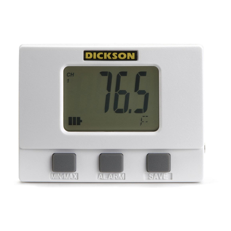
Dickson SM300 User manual

DICKSON
DICKSON
SM300/SM320/SM325
TM320/TM325
LCD Display Loggers Operation
Getting Started
Please refer to the “Software and Logger Operations”
section of this manual for more Setup and Download
instructions.
Note:
Make sure thermocouple probes are connected for
SM320/SM325 models.
•
The logger is now sampling and ready for use,
a Delta
(
Δ
) symbol will appear in the display to con rm
logging
. The default sample interval is 1 minute.
You may choose to change Default settings for sample
interval and start-date and time. When changing
these settings, the logger will automatically go
through the clear process to accept your changes.
Note:
To achieve longer battery life during operation,
use a less frequent sample rate, disconnect the unit
from the USB port when not downloading data, limit the
frequency of memory card transfers, and DO NOT insert
the memory card all the way unless downloading.
•
Install version 8.0 or higher of DicksonWare™
Software (compatible with Windows® 98 or higher).
•
Connect the cable (supplied with the software) to
the logger and to a working serial or USB port on
your computer.
•
If using the USB connection, your computer may
detect the logger when the logger is powered on and
connected to the computer via the USB
connection. Depending on your version of Windows,
the computer may go through an Add New Hardware
routine.
•
Click the Setup button.
You will be prompted to to
select a USB or Serial COM Port connection, then click
Continue. A Setup window will appear, and
all elds
should be automatically lled in, this will con rm
that DicksonWare™ has recognized the logger.
Should all elds remain blank, refer to “No
Communication” in the Troubleshooting section of
this manual. Once DicksonWare™ recognizes the
logger, press the Clear button. This will delete all data
currently stored.
SM300
SM320
SM325
SM325
TM325
TM320
www. .com information@itm.com1.800.561.8187

Note:
The loggers have a continuous display that cannot
be disabled. Dual variable models such as the TM320/
TM325 and SM325 will toggle between Temperature and
Humidity or two Temperature readings automatically. The
SM320/325 models will read PROB on the display if the
Thermocouple is not connected.
Button Functions:
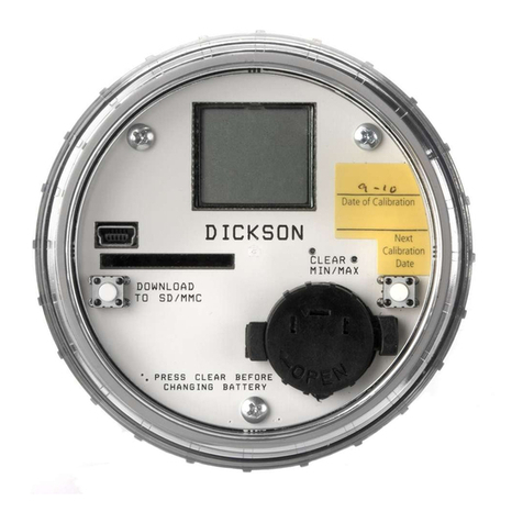
Save
Note:
This feature is only for use with the Dickson
Memory Cards.
Pressing this button will download any data stored in
the logger to the removeable memory card. STORE will
appear on the display momentarily and the counter will
start counting down from 100. DO NOT remove the
memory card until STORE is no longer in the display and
the unit is displaying current readings.
Note:
Leaving the memory card installed in the Logger
will reduce battery life by 50%. If you notice “Err” on the
display, please refer to the Trouble Shooting section of
this manual.
Alarm
Pressing this button will silence the alarm. Holding this
button down for about 5 secounds will toggle between
Fahrenheit and Celsius. (Alarm parameters can only
be set in DicksonWare™. Refer to the DicksonWare™
software manual.)
MIN/MAX
Pressing this button will start the Min/Max display cycle.
Clearing MIN/MAX Values
Holding the “MIN/MAX” and “ALARM” buttons down
together until “clr” appears on display will clear the
stored minimum and maximum values. The Min and
Max displayed by the logger will be the minimum and
maximum values sensed since it was last cleared.
Note:
DicksonWare™ will show the minimum and
maximum values of the downloaded data. These could
be different than that displayed on the unit itself.
For Example:
Your logger is set for a 2 minute sample
which is good for about 11 days. After 5 days you clear
MIN/MAX. After another 6 days you download the
logger. The Min/Max displayed by the logger will be the
MIN/MAX for the last 6 days. The MIN/MAX shown by
DicksonWare™ will be the Min/Max for the last entire
11 days. Dew point MIN/MAX in the TM320 and TM325
models are not updated unless dew point is enabled
using DicksonWare™ software.
Battery Replacement
To replace the batteries (4 “AA” alkaline) remove the
screw on the back of the case.
Installing a Flash Memory Card Reader
Follow the instructions included with the ash card
reader. Additional information and trouble shooting
information on the card reader can be found at that
manufacturers website.
Logger Operating Instructions
Useful Features
Export Data
A snapshot of your graph or a real-time graph of points
can be easily exported to other programs such as Excel™
or PowerPoint™.
Super Size Storage
With the use of the optional Flash Memory Card and
reader you can store 100 Full Data Loggers. This elimi-
nates the need to physically remove your loggers from
their application for uninterrupted monitoring.
** CLICK ON THE FEATURES BUTTON IN THE **
SOFTWARE FOR DETAILED INSTRUCTIONS ON
HOW TO USE ABOVE FEATURES
Real Time Monitoring
Monitor and graph your process as it happens and print
and save from real time screen. (This feature should
be used sparingly as it causes the battery to drain very
quickly unless using optional AC adapter)
Customize Graphed Data
DicksonWare™ calculates Min, Max and Average
of all data collected. Customize data by eliminating
unnecessary data points and customize Min, Max and
Average to show only desired information.
SETUP
Click this button rst to establish communication
between your Logger and DicksonWare™ software.
You will be prompted to select a USB or Serial COM Port
connection, then click Continue. A Setup window will
appear with ALL elds populated, this con rms that the
software has recognized the logger. Should all elds
remain blank and communication is not established, refer
to the Troubleshooting section of this manual. There are
three tabs within the Setup window:
Basic Software & Logger Operating Instructions
Identi cation
Provides you with the Model and Serial number of the
logger as well as the option to set a custom User Id by
clicking the active Setup to the right of the User Id eld.
Samples
Majority of the setup process takes place in this section.
Each eld with an active Setup button to the right is a
parameter that you can customize. Sample Interval is for
telling your logger how frequently you want it to take
www. .com information@itm.com1.800.561.8187

TM320
TM325
Operating Range
(unit only)
-4 to +158°F
-4 to +158°F
(non-condensing)
(non-condensing)
Int. Temperature Sensor
Int. Temperature Sensor
Thermistor
N/A
Int. Temperature Accuracy
Int. Temperature Accuracy
±0.8°F
N/A
Ext. Temperature Sensor
Ext. Temperature Sensor
N/A
Thermistor
Ext.Temperature Range
Ext.Temperature Range
N/A
-40 to +176°F
Ext.Temperature Accuracy
Ext.Temperature Accuracy
N/A
±0.8°F
R/H Sensor Type
R/H Sensor Type
Capacitive
Capacitive
Capacitive
Capacitive
% RH Accuracy
±2% @ 73°F
±2% @ 73°F
0 to 95%
0 to 95%
Storage Capacity
Storage Capacity
32,000 (div. x 2)
32,000 (div. x 2)
Resolution
0.1°
0.1°
Response Time (63%)
Response Time (63%)
2.5 minutes typical
2.5 minutes typical
2.5 minutes typical
2.5 minutes typical
Speci cations
SM300
SM320
SM325
Operating Range
(unit only)
-4 to +158°F
-4 to +158°F
-4 to +158°F
(non-condensing)
(non-condensing)
(non-condensing)
Int. Temperature Sensor
Int. Temperature Sensor
Thermistor
Thermistor
N/A
Int. Temperature Accuracy
Int. Temperature Accuracy
±0.8°F
±1.8°F
N/A
Ext. Temperature Sensor
Ext. Temperature Sensor
N/A
Thermocouple
Thermocouple
Thermocouple (x2)
Thermocouple (x2)
Ext.Temperature Range
Ext.Temperature Range
N/A
-300 to +2000°F
-300 to +2000°F
Ext.Temperature Accuracy
Ext.Temperature Accuracy
N/A
±1.8°F (unit)
±1.8°F (unit)
R/H Sensor Type
R/H Sensor Type
N/A
N/A
N/A
% RH Accuracy
% RH Accuracy
N/A
N/A
N/A
Storage Capacity
Storage Capacity
32,000
32,000 (div. x 2)
32,000 (div. x 2)
Resolution
0.1°
0.1°
0.1°
Response Time (63%)
Response Time (63%)
2.5 minutes typical
2.5 minutes typical
1 minute
1 minute
Accessories
Description
Order #
DicksonWare™ Software & USB Download Cable
A016
DicksonWare™ Sofware & Serial Download Cable
A015
DicksonWare SECURE Software & USB Download Cable (21CFR11 Compliant)
A026
DicksonWare SECURE Software & Serial Download Cable (21CFR11 Compliant)
A025
Card Reader w/ FLASH Memory Card
A220
Extra FLASH Memory Card
A210
AC Adapter
R157
NIST Traceable Calibration 3-pt. (new unit)
N300
NIST Traceable Calibration 1-pt. (new unit)
N100
A2LA Accredited Calibration 3-pt. (new unit)
N400
and store readings. This can be done in 10 or 1 second
intervals. The dialog box that allows you change the
sample interval will also inform you of how much time
your chosen sample rate will cover. Sub Ten Second
interval should enabled for desired sample intervals with
less than a 10 second interval. Stop or Wrap when Full
determines what the logger should do when it has col-
lected all possible samples, either STOP and shut down,
or continue logging by Wrapping the newest data over
the oldest.
Channels
By clicking the Adjust / Customize button to the right of
the temperature or Humidity value for each channel, you
will be allowed to Disable a channel that is not neces-
sary, change the name of a channel, set and activate
Alarm parameters.
Download
Clicking this button will automatically extract all logged
data into a Graph and Table format for you to view. You
may also choose to retrieve data via the optional Flash
Memory Card. After Saving data to the card, simply
insert the card into your reader, open the LOG Folder,
then double click on the appropriate LOD le which will
automatically open DicksonWare™, if not, manually
open DicksonWare™. Form the top Menu bar, click on
File > Open and browse to the appropriate drive for your
reader and select the LOD le.
www. .com information@itm.com1.800.561.8187

DICKSON
Troubleshooting
the unit. Place unit in a warm dry environment for
24 hrs. Clear memory and try again. These loggers are
designed for use in a non-condensing environment.
If the environment creates condensation, try placing
the unit (temperature only models) in a small sealed
plastic bag to protect it from condensation.
•
If possible, try another PC, and/or another USB port.
•
If the logger appears to be frozen or non operational,
try the following: Open the unit by removing the
screw on the back of the case and remove and
reinstall or replace the batteries.
NOTE:
Removing the battery will not erase any stored
data
Unit will not turn on or frozen display
•
Unit may be “locked up”, try removing the battery
and then replacing after a few moments.
•
Battery may be to low or dead, replace batteries
The display reads Prob on RF (remote probe)
•
(This would be for SM320 and SM325’s only), it
means that the unit does not recognize the external
probe, check to see that it is connected properly. If
it is connected properly, there may be a weak internal
connection and should be returned.
•
Is there an extension cable being used? It could be
defective. Omit the extension cable and try another
K-type probe.
Channel shows extreme reading on the graph
•
This is normal when an activated channel has no
probe connected at the time a sample is taken.
No communication - Serial Connection
•
Verify that you have the correct version of
DicksonWare™ software installed on your PC. Version
8.0 or higher is required for models SM300, SM320,
SM325, TM320 and TM325.
•
Verify that the correct COM port is selected: From
the main Dicksonware screen, click on Logger then
Communication, a black dot will appear next to the
selected COM port. You may need to select a different
COM port. Should you get an error message stating
that ”Device Is Already Open”, this could mean that
you have the proper COM port selected, but another
device, or it’s software, has it allocated. Palm pilots,
for example, will cause this problem, in which case
the port is not actually “available” and you may have
to disable that device.
•
You may need to relocate the download cable to
another serial port on the back of the PC and possibly
try changing the COM port again in DicksonWare™.
•
If communication has not been established with the
previous steps, you may need to open the logger and
press the reset button and then try all COM port and
cable combinations again.
•
If possible, try another PC
•
Make sure the USB is unplugged, and that “USB” is
NOT checked in File > Preferences > Serial.
No Communication - USB Connection
•
Make sure that “USB” is selected under File >
Preferences > Serial.
•
Unplug USB cable and plug back in.
•
Remove all power to the logger (this will not cause the
unit to lose any data within the logger, but
you will have to start the unit logging again using
DicksonWare™) unplug the USB cable, power the
logger back on, then reconnect the USB cable.
•
If the logger was used in a moist or humid
environment Condensation may have formed on
Factory Service and Returns
NOTE:
Dickson shall not be liable for consequential or
incidental damages resulting from failure or malfunction
of its products.
Contact the factory for a Return Authorization (RA)
Number before returning any instrument. The model
number, serial number and a purchase order number will
be requested before an RA number is issued.
Error Codes
Err 1
.........................
No memory card
Err 2
.........................
Memory card locked or protected
Err 23
.......................
Memory card requires reformatting
Err 66
.......................
Memory card full
CE testing has found that when using unshielded thermocouple probes in a strong RF eld in the 350 to 400 MHz
frequency range, the reading may be off by several degrees.
www. .com information@itm.com1.800.561.8187
This manual suits for next models
4
Other Dickson Data Logger manuals
Dickson
Dickson SK500 User manual

Dickson
Dickson SP125 User manual
Dickson
Dickson SM300 User manual
Dickson
Dickson TP325 User manual
Dickson
Dickson WiZARD2 User manual
Dickson
Dickson HT300 User manual
Dickson
Dickson SP100 User manual
Dickson
Dickson DBL User manual
Dickson
Dickson ES120A User manual
Dickson
Dickson PR120 User manual
Dickson
Dickson VFC320 Installation and operation manual
Dickson
Dickson TP425 User manual
Dickson
Dickson PR350 User manual
Dickson
Dickson PR100 Instruction Manual

Dickson
Dickson SP100 Instruction Manual
Dickson
Dickson ES120 User manual
Dickson
Dickson SR200 User manual
Dickson
Dickson SP125 User manual
Dickson
Dickson HT100 User manual

Dickson
Dickson SK180/500 User manual
