Communication Connection(BMS/Meter/CT/DRM/COM)Monitoring OperationFirmware Upgrading614.00496.01x
LN
Electric meter connection diagram ON OFFPV 1PV 2BATBMS CANDRM Upgrade DONGLE MET ER/CT COM/LCD CT connection diagramLCD settingsTo select CT, you need to enter Use setting ,then enter CT or Meter Setting.
>Select CT
CT/Meter Setting
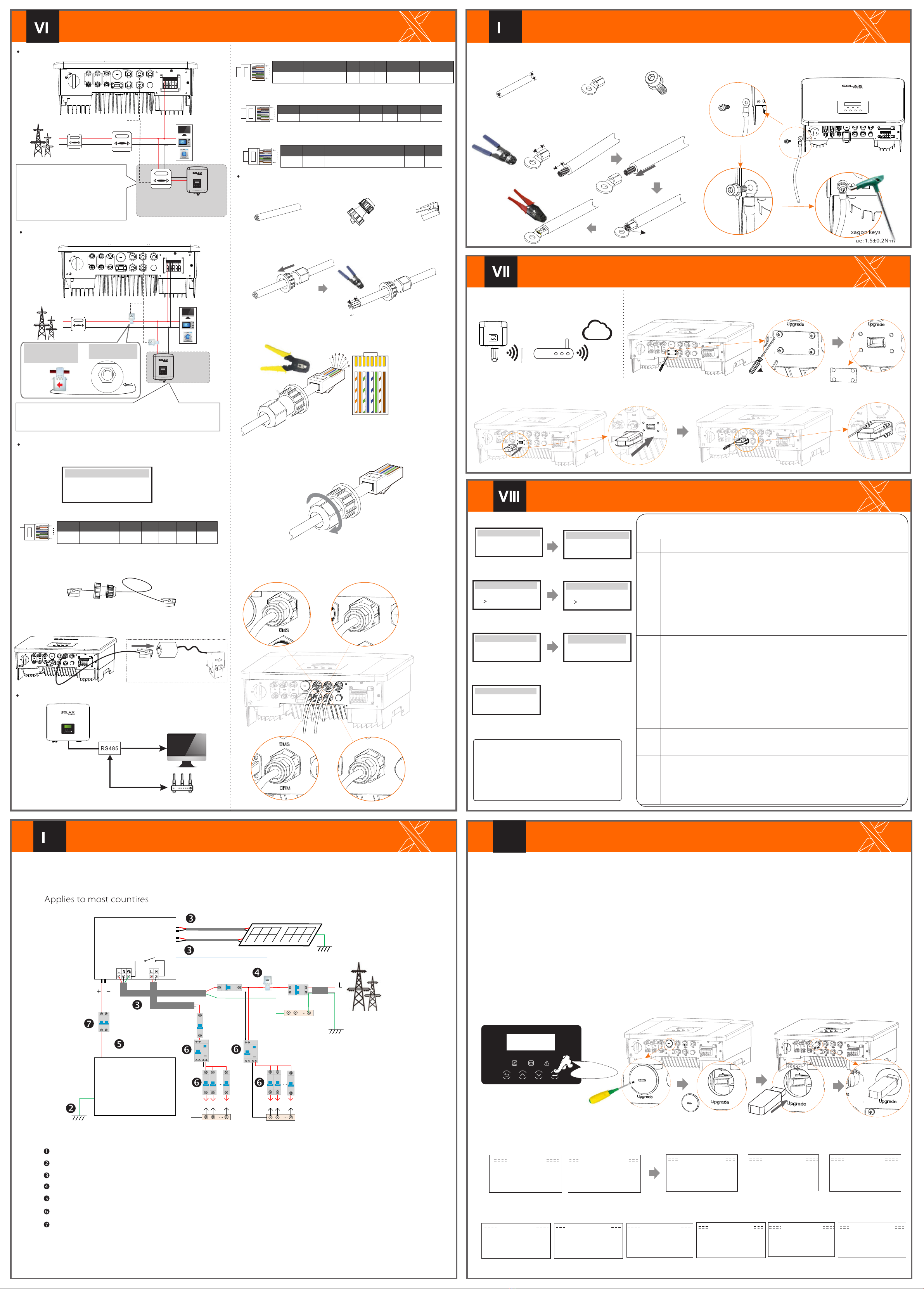
Step 1. Prepare a communication cable, and then find the communication adapter in the accessory bag.Step 2 Insert the communication cable through the communication adapter, and peel off the outer insulation layer of15mm.
15.00mm
Diagonal pliers12345678Step 3. Insert the prepared communication cables into the RJ45 terminalsin sequence , and then use network cable crimping pliers to press them tightly.Step 4. Tighten the completed BMS / Meter / CT / DRM / COM / LCD communication line and tighten the waterproof plug. Communication Connection StepsCOM CommunicationStep 5: Finally, find the corresponding BMS / Meter / CT / DRM / COM / LCD poets on the inverter and insert the communication cable into the corresponding ports.Meter/CTMeter/CTCOM/LCDStart InverterxØDongle connection diagram RouterWireless monitoring accessories connection steps:ØStep 1. Of the Dongle port of the inverter needs to unscrew the screw and take off the cover.SolaX Could
DONGLE
CoverPhillips screwdriverTorque: 1.2±0.1N·mDongleStep 2. Insert the Pocket WiFi Plus into the Dongle port, use the four screws in the Pocket WiFi Plus accessory bag and tighten them.
DONGLE
NGLE
Start Guide
EnglishDeutschItalianLanguage2.Set language2017 ->06 <-0610:19Date time1.Set date time
CountryVDE0126Safety
3.Set the safety standard
CTMeterCT/Meter Setting
4.CT/Meter Setting
Export controlUse Value:10000W
Export Control
This function allows the inverter able to control energy exported to the grid. There are user value and factory value. The factory value is default which can not be charged by user. The user value set by installer must be less than the factory value.
5.Set export control*
There are 4 work modes for choice. Self use/ Back Up Mode/ Feed in Priority/ Force Time Use
All these work modes is available for on-grid condition only:
>disable enable X1-Matebox Setting7.X1-Matebox Setting
-In order to upgrade the firmware smoothly, if the DSP and ARM firmware needs to be upgraded, please note that ARM firmware must be upgraded first, then DSP firmware!-Make sure that this directory is completely consistent with the above table, do not modify the firmware file name, Otherwise, the inverter may not work!-For X1-Hybrid G4, ensure that the PV input voltage is greater than100V (upgrade on sunny days). please ensure that the battery SOC is greater than 20% or the battery input voltage is greater than 90V. Otherwise, it may cause serious failure during the upgrade process!-If the ARM firmware upgrade fails or stops, please do not unplug the U disk and power off the inverter and restart it. Then repeat the upgrade steps.Upgrade preparation1) Please check the inverter version and prepare a U disk (USB 2.0) and personal computer before upgrading.2) Please contact our service support through service@solaxpower.com to obtain the firmware, and store the firmware in the U disk according to the following path. Ø
Update: For ARM file:“update \ARM\618.00361.00_Hybrid_X1G4_ARM_V1.01.0710.usb”; For DSP file:“update\DSP\618.00360.00_Hybrid_X1G4_DSP_V1.01.0710.usb”;
Upgrade stepsStep 1. Please save the "Upgrade" firmware in your U disk first, and press the "Enter" button on the inverter screen for 5 seconds to enter the OFF mode. ØStep 2. Locate the "update" port of the inverter, use a flat-blade screwdriver or coin with the same width to remove the waterproof cover, and insert the U disk.Waterproof cover
U Disk
Step 3. LCD operation, enter the upgrade interface "update", as shown below(a): Please press the up and down keys to select ARM, then press the bottom of the page to select "OK", press the enter key to enter the software version interface ;Update ARM Cancel>OK>ARMDSPUpdate (ARM )
Update ( ARM)
>618.00361.00_Hybrid_X1G4_ARM_V1.010710.usb(c)>ARMDSP(e)Upgrading---------25%(d)(a)(b)Step 4. Please confirm the new firmware version again and select the firmware to upgrade. The upgrade takes about 20 seconds.(d) When it is completed, the LCD screen returns to the "Update" page.(k)Update(DSP)Upgrade Successful
Update(DSP)
connect---------Update DSP File >618.00360.00_Hybrid_X1G4_DSP_V1.01_0710.hex(g)Update Selection ARM>DSP( f)(h)
Update(DSP)
Upgrading---------25%Update(DSP)(i)(j)DSP Erasing---------NameDescriptionOff-gridSelf Use
Backup
Feed-in
6.Set work mode*>Mode Select self useWork Mode
5*.Export Control
mode
priority
6*.Set work mode
Update ARM FileUpdate9( ARM)
DRM4/8+3.3VDRM0GNDGND
The DRM pin is defined as follows:
DRM1/5DRM2/6DRM3/712345678
18Ø Meter /CT PIN is defined as follows:
12345678
18
485A485BXCT1-2CT1-1CT2-2CT2-1X
ØCOM PIN DefinitionØ The BMS pin is defined as follows:Ø
Phillips screwdriverTorque: 1.2±0.1N·mFlat-blade screwdriver or coin(Port size: 12*2mm;Torque: 1.5±0.2N·M)Long press for 5 secondsGrounding Connection(manodatory)xStep 2. Strip the grounding cable insulation(length”L2), insert the stripped cable into the ring terminal, and then clamp it.
L1
12AWG
C
L2=L1+3mm
Diagonal pliersLeaking cableCrimping ToolStep 1. Prepare a one-core cable (12AWG), and then find the ground terminal in the accessories.Hexagon keysTorque: 1.5±0.2N·mStep 4. Find the ground connection port on the inverter, and screw the ground wire on the inverter with an M5 Allen key.
Start inverterØ
GridHousehold MeterSingle-phase meterLoadMete1Meter2
Communication cableWaterproof connector with Rj45Multifunction terminalcrimping tool (RJ45)1) White with orange stripes2) Orange3) White with green stripes4) Blue5) White with blue stripes
6) Green
7) White with brown stripes8) BrownAfter the inverter is checked, the inverter will take the following steps:Turn on the Load switch and Off-grid switchTurn on thebattery switch.Make sure the battery is well connected.Make sure the CT is connected.Confirm that all DC lines and AC lines are connected.Make sure that the inverter is fixed on the wall.Long press Enter for 5 seconds to exit the shutdown mode. Mode is the mode when it is turned off for the first time; factory default: off mode)Ensure that all ground wires are grounded.One-core cable (12 AWG)OT terminalHexagon socket screws
If the user has other power generation equipment (such as inverters) at home and wants to monitor both, X1-Hybrid G4 inverter provides Meter2 communication function to monitor the power generation equipment.For more information, please contact SolaX.
Other power generation equipment
X1X1
L LineCT
Public grid electricity
Meter/CT port is at the bottom of the inverter.Note:The arrow on the CT must point at the public grid.
Meter/CT
GridHousehold MeterLoadsLNOther power generation equipment
ON OFFPV 1PV 2BATBMS CANDRM Upgrade Dongle Met er/CT COM/LCD
X1X1
CT 1CT 2
If the user has other power generation equipment (such as inverter) at home and wants to monitor both, X1-Hybrid G4 inverter provides CT2 communication function to monitor the power generation equipment.
Data ReadData ReadData WriteSmart control device(developing) Donglengle
18
BMS_CANHGNDBAT_TEMPGNDBMS_CANL23456781XBMS_485ABMS_485B
NBATBatteryN-BAR for loadsN-BAR for off-grid loadsoff-grid loadsLoadsX1-Hybrid G4 PV 1PV 2E-BARRCDBreakerGridBreakerGridOff-gridMain Breaker
BreakerBreaker
CTCT
Breaker
PERCD1) To connect the Communication line of the CT line, the lines need to be made on both sides, connecting the RJ45 terminal on one side and the Communication line Adapter on the other.CANMe ter/C T COM/LCD distribution box 2) One side of the finished cable, Communication line adapter is inserted into the inverter, and one side of the RJ45 terminal is inserted into the CT connection.The self-use mode is suitable for areas with low feed-in subsidies and high electricity prices.① When the power of PV is sufficient Active Charging or Discharge time period:PV will power the loads rstly, and surplus power will charge to the battery .If the battery is fully charged, then sell the surplus power to the grid;(The inverter will limit the output if Feed-in limit or zero feed-in is needed ) (PV>Load ,PV →Load→Battery → Grid) ② When the power of PV is insufficient Active Charging time period: PV will power the loads rstly ,the remaining power will be taken from the grid , the battery will not discharge at this time.(PV>Load ,PV + Grid → Load) Active Discharge time period: PV+BAT will power the loads together. If the power is still not enough, the remaining power will be taken from the grid. (PV<Load ,PV + Battery + Grid → Load) ③ Without PV power Active Charging time period: The grid supplies the loads and also can charge the battery.(PV=0 ,Grid →Load + Battery)Active Discharge time period:The battery will power the home loads rstly.If the battery power is not enough ,the remaining power will be taken from the grid .The inverter will enter into the standby state.(PV=0 ,Battery+Grid→Load) Battery min SOC can be set:10%-100%.The Feed-in priority mode is suitable for areas with high feed-in subsidies, but has feed-in power limitation.①When the power of PV is sufficient Active Charging time period :PV will power the loads rstly, and surplus power will feed-in to the grid. If the feed-in power has been limited ,the surplus power can charge the battery. (PV>Load ,PV → Load → Grid → Battery) Active Discharge time period:PV will power the loads rstly ,and surplus power will feed-in to the grid. (PV<Load ,PV → Load → Grid )②When the power of PV is insufficient Active Charging time period :PV will power the loads rstly, the remaining power will be taken from the grid. The battery will not discharge.(PV>Load,PV + Grid → Load) Discharge time period: PV+BAT will power the loads together. If the power is still not enough, the remaining power will be taken from the grid. (PV<Load ,PV + Battery + Grid → Load)③Without PV power Active Charging time period :The grid will power the home loads and also charge the battery.(PV=0 , Grid → Load + Battery) Active Discharge time period :The battery will power the home loads rstly .If the battery power is not enough,the remaining power will be taken from the grid .The inverter will enter into the standby state.(PV=0 , Battery+Grid → Load) Battery min SOC can be set:10%-100% The back-up mode is suitable for areas with frequent power outages.Same working logic with “Self-use” mode.This mode will maintain the battery capacity at a relatively high level.(Users' setting) to ensure that the emergency loads can be used when the grid is off. Customers no need to worry about the battery capacity.Battery min SOC can be set:30%-100%.Backup mode SOC adjustment range :30%-100%;In Backup mode, SOC-min under off-grid condition is 10%, which cannot be modied. The off-grid mode is used when the power grid is off .System will provides emergency power through PV and batteries to supply power to the household loads. (Battery is necessray)①When the power of PV is sufficentPV will power the loads rstly, and surplus power will charge to the battery.(PVLoad ,PV Load Battery) ②When the power of PV is insufficientThe remaining power will be taken from the battery.(PVLoad ,PV Load)③Without PV powerThe battery will power the emergency loads until the battery reached the min SOC,then the inverter will enter into the idle mode.(PV=0, Battery Load)RJ45 terminals*1The ground wire port of X1-Hybrid G4 M series inverter has been connected, and the D series needs to be wired according to the following steps.
12345678
18
485A485BGND
Drycontact_A(in)Drycontact_B(in)Drycontact_A(out)
Drycontact_B(out)
+13V


