Soldo S.r.l.
Via Monte Baldo, 60
25015 Desenzano d/G (Brescia) Italy
Tel +39 030 999.13.09 - Fax +39 030 914.19.77
http: //www.soldo.net
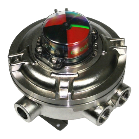
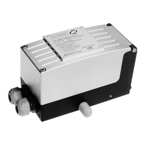
Installation & Operating Manual
IOM-SX_SH01-01 SX
SH
IOM-SX_SH01-01 Page 1 / 2
READ THIS INSTRUCTION FIRST
To avoid serious or fatal personal injury or major property damage, read and follow all safety instruction in this manual.
If you require additional assistance, please contact SOLDO.
SAVE THIS INSTRUCTION
Declaration of conformity as defined by the
ATEX directive 94/9/EC
Doc.: CE001-06
Herewith we declare that the SOLDO “limit switch box SX series”,
II 2 G Ex d IIB T6/T5/ T4
II 2 D Ex tD B21 T85°C/T100°C/T135°C
and the SOLDO “limit switch box SH series”,
II 2 G Ex d IIB+H2 T6/T5/ T4
II 2 D Ex tD B21 T85°C/T100°C/T135°C
are in conformity with the provision of the ATEX directive 94/9/EC “Equipment or Protective
Systems intended for use in potentially explosive atmospheres” and with national
implementing legislation and that appropriate harmonized standards have been applied:
EN 60079-0 : 2006 EN 60079-1 : 2007 EN 61241-0 : 2006 EN 61241-1 : 2004
Directive 89/336/CEE Electromagnetic compatibility.
EN 61326-1:2006
Directive 73/23/CEE Low tension
EN 60529:1991 EN 60730-1:2000
EC- Type examination certificate
ATEX: ITS 09ATEX 16281X IECEx: IECEx ITS 09.0020X
Production quality assurance notification:
ATEX: ITS 08ATEXQ5820 IECEx: GB/ITS/QAR09.0004/00
WARNING!
Warns of hazard that MAY cause serious personal injury, death or major property damage.
HAZARDOUS VOLTAGE. Disconnect all power before servicing equipment.
DO NOT REMOVE COVER WHEN ENERGISED.
CAUTION !
Do not exceed the limit switch performance limitation. Exceeding the limitation may cause damage to the limit
switch, actuator and valve.
The conduit plug supplied with the switch boxes are for transit purposes only. IP67 protection depends on
cable gland and cabling methods used. Limit switchbox for quarter-turn valve device (90° rotation).
Maximum shaft angular velocity 250 rpm.
Follow switch adjustment & indicator setting before servicing the limit switch box.
1 INSTALLATION
1.1 Attach proper mounting bracket (1) to the box (4) housing using four M 6X8 bolts (2).
1.2 Align shaft (5) to actuator shaft and engage it.
1.3 Attach bracket to actuator using hardware provided (3).
2 SWITCH ADJUSTMENT
2.1 Loose the screws (8) and remove box cover (7).
2.2 Follows indication in “Cams setting” Page 2.
2.3 Box with 3-4 switches, set the actuator in the extra position you have to signal. Act according to indications
in “Cams setting ” to set cams of the switch number 3 and 4.
2.4 Replace box cover (7). WARNINGS: check seal (6) is properly fitted in slot. Turn manually cover’s shaft (15)
cheeking to align it to switch box shaft and engage it. Tightening screws (8).
GB For other languages visit WWW.SOLDO.NET
IT Per altre lingue visitare il sito WWW.SOLDO.NET
FR Pour les autres langues visite WWW.SOLDO.NET
DE Für andere Sprachen besuchen WWW.SOLDO.NET
ES Para otros idiomas, visite WWW.SOLDO.NET
Safety instruction to hazardous area installation
Doc.: SI001-03
Model numbers covered SX_ _ _ _ _-_ or SH _ _ _ _ _-_ ( _ indicates options in switches,
switches quantity, terminal strip, colour, cable entries). The following instructions applies to
equipment covered by ATEX certificate number: ITS 09ATEX 16281X
And by IECEX certificate number: IECEx ITS 09.0020X
SX limit switch boxes may be used in an hazardous area with flammable gases, vapours and
powder, group IIB with the following temperature classes:
T6: -25°C ≤T amb. ≤+ 60° C Surface temperature T 85°C
T5: -25°C ≤T amb. ≤+ 75° C Surface temperature T 100°C
T4: -25°C ≤T amb. ≤+ 105° C Surface temperature T 135°C
Special options for -40°C
defined by “LT1” at the
end of the switch box code
SH limit switch boxes may be used in an hazardous area with flammable gases, vapours and
powder, group IIB+H2 with the following temperature classes:
T6: -25°C ≤T amb. ≤+ 60° C Surface temperature T 85°C
T5: -25°C ≤T amb. ≤+ 75° C Surface temperature T 100°C
T4: -25°C ≤T amb. ≤+ 105° C Surface temperature T 135°C
Suitably trained personnel shall carry out installation in accordance with applicable code of
practice
The user should not repair this equipment.
The user should provide suitable systems to limit heating coming from valve; max ambient
temp 105°C
If the equipment is likely to come into contact with aggressive substances, it is responsibility of
the user to take suitable precautions that prevent it from being adversely affected, thus
ensuring that the type of protection is not compromised. Agressive substances – es. Acidic
liquids or gases that may attack metal .
The following precautions must be observed:
i The metallic alloy used for the enclosure, in the event of a rare accident, could cause ignition
sources due to impact or friction (sparks may occur). This shall be considered when the box is
installed in group II category 2G areas.
ii Due to electrostatic charge of plastic pieces, the limit switch box shell only be cleaned with a
damp cloth.
NOMENCLATURE
SX
SH 01 2 0 0 - 1 -Extra digit
To define
special option
Cable entry
Colour
Terminal strip
Switch quantity
Switch type
