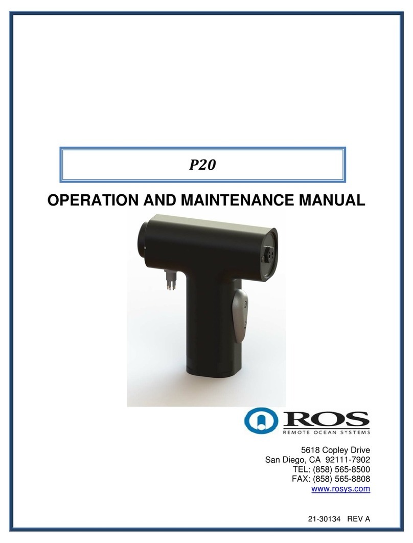
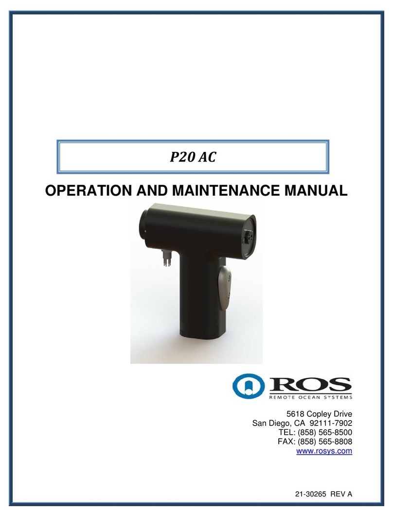
Ros P15 User manual

21-30454 REV C
OPERATION AND MAINTENANCE MANUAL
5618 Copley Drive
San Diego, CA 92111-7902
TEL: (858) 565-8500
FAX: (858) 565-8808
www.rosys.com
P15
LightWeightPan&Tilt
Positioner–HalfDuplex

21-30454 REV C
II
TABLE OF CONTENTS
WARRANTY ..................................................................................................................III
CUSTOMER ASSISTANCE...........................................................................................IV
CHANGE RECORD........................................................................................................V
1WARNINGS.............................................................................................................1
2PRODUCT SPECIFICATIONS ................................................................................2
3INSTALLATION.......................................................................................................3
4OPERATION............................................................................................................4
5MAINTENANCE.......................................................................................................4
6TROUBLESHOOTING.............................................................................................5
7REFERENCE DOCUMENTS...................................................................................5
Table of Tables
Table 1. P15 Product Specifications ...............................................................................2
Table 2. Trouble Shooting...............................................................................................5
Table of Figures
Figure 1. P15 Overall Dimensions...................................................................................3
Figure 2. P15 Mounting Points........................................................................................3
Figure 3. P15 Standard Pinouts ......................................................................................4

21-30454 REV C
III
WARRANTY
ROS, Inc. (hereinafter called "ROS") warrants its products as stated below subject to the
conditions specified.
ROS warrants its products, when operated under normal conditions, to be free from defects in
material or workmanship for a period of two years from the date of purchase provided that
inspection by ROS discloses that such defects developed under normal and proper use. ROS
products repaired or replaced pursuant to this warranty shall be warranted for the unexpired
portion of the warranty applying to the original product. The liability of ROS under this warranty
shall exist subject to the following conditions:
(a) Purchaser properly notifies ROS of such defects and the defective product is
returned to ROS, transportation charges paid by Purchaser.
(b) ROS shall be released from all obligations under its warranty in the event repairs
or modifications are made by persons not authorized by ROS.
(c) Representations and warranties made by any person, including distributors and
representatives of ROS, which are inconsistent or conflict with the terms of this
warranty, shall not be binding upon ROS unless reduced to writing and approved
by an officer of ROS. ROS shall in no event be liable for other direct, special,
incidental, consequential, indirect or penal damages.
(d) The laws of the State of California shall govern this warranty.
In the event the defect is determined to be within the terms of this warranty then ROS agrees to
repair and/or replace (at ROS' discretion) the product or defective portion at no charge to the
Purchaser. This warranty does not apply to expendable items or to normal wear-and-tear, and
is conditional upon performance of normal preventative maintenance procedures.
Our commitment to quality and customer service directs us to constantly strive to improve our
products. The materials and specifications presented in our manuals and data sheets are
correct and accurate to the best of our knowledge, and are presented in good faith. However,
the information is not guaranteed and is subject to change without notice.
LIMITATIONS OF REMEDIES
Purchaser assumes all risk and liability for results obtained in any installation, operation, or use
of the product. Purchaser’s sole remedy for any breach of warranty by vendor shall be limited to
the “express remedies” set forth above. Otherwise, in no event shall vendor, its agents, or
employees be liable to the original purchaser or any third party for any consequential or
incidental damages or expenses of any nature arising directly out of or in connection with the
use of vendor projects, even if vendor has been advised of the possibility of such damages or
expenses. In any event, unless otherwise contrary to state law, vendor liability under this limited
warranty shall not exceed the purchase price of the product.

21-30454 REV C
IV
CUSTOMER ASSISTANCE
If you have any questions or problems that are not covered by this, please contact our
representative in your area. You may also contact us directly by phone, FAX or e-mail.
TEL: (001) 858-565-8500
FAX: (001) 858-565-8808
Web Site: www.rosys.com

21-30454 REV C
V
CHANGE RECORD
REV DESCRIPTION DATE
A PRODUCTION RELEASE (EC-02652) 29SEP16
B SEE EC-02667 19OCT16
C SEE EC-03012 20MAR19

21-30454 REV C
1
1 WARNINGS
WARNING: Disconnect the P15 from power source prior to servicing.
Failure to do so may cause property damage, personal injury and/or
death.
WARNING: Disconnect cables from power source prior to connecting
to the P15. Failure to do so may result in damage to the unit.
WARNING: Dropping the P15 could result in personal injury and/or
damage to the unit.
WARNING: Proper care and handling of the P15 and associated
cables must be observed. Failure to do so may result in connector
damage and/or water infiltration.

21-30454 REV C
2
2 PRODUCT SPECIFICATIONS
Table 1. P15 Product Specifications
Mechanical
Housing Material Hard Anodized Aluminum
Mounting 4X (Pan) & 2X (Tilt) .266in Dia. Holes
Weight in Air 6.6 lb (3.0 kg)
7.7 lb (3.5 Kg) PBOF*
Weight in Water 3.1 lb (1.4 kg)
4.2 lb (1.9 Kg) PBOF
Size 8.2in x 7.1in x 3.8in
Electrical
Voltage 20-28 VDC
Current 2A max
Communication RS-485 (half duplex)
Environmental
Depth Rating 70 MSW (230 ft)
6000 MSW (20,000 ft) PBOF
Min/Max Operating Temperature (in water) -10°C to 50°C
Storage Temperature (in air) -20°C to 60°C
Performance
Payload 15 lb (6.8 kg)
Torque 10 ft-lb (13.5 N-m)
Accuracy ±0.3°
Resolution 0.01°
Scan Range 0 - 360° (both axes)
Rotation Speed 20°/s (both axes)
*PBOF = Pressure Balanced Oil Filled

21-30454 REV C
3
3 INSTALLATION
Figures 1 and 2 provide overall dimensions and mounting features for the P15 (all
dimensions are in inches).
Figure 1. P15 Overall Dimensions
Figure 2. P15 Mounting Points
Figure 3 provides the pin-out. Note: that Figure 3 shows the standard pin-out for the
P15. Customer specified pin-outs may differ.

21-30454 REV C
4
PIN 1: +24VDC RETURN
PIN 2: +24VDC
PIN 3: RS-485 Tx/Rx+
PIN 4: RS-485 Tx/Rx-
PIN 5: COMMUNICATIONS RETURN (OPTIONAL)
Figure 3. P15 Standard Pinouts
4 OPERATION
The P15 is operated by issuing sequential commands through a serial interface.
See Refs. 3 for command sets and operating examples.
5 MAINTENANCE
The P15 is intended to be maintenance free. Seals do not require periodic
replacement. Lubricant is applied on the external connectors and o-rings at the factory.
Although the P15 is constructed of corrosion resistant materials, we recommend careful
handling procedures be used to prevent deep scratches or dents. Improper handling
can damage the anodize coating and create localized corrosion.
In the event the P15 stops working, please contact ROS customer service. For
troubleshooting guidelines see section 6.

21-30454 REV C
5
6 TROUBLESHOOTING
This section provides information on trouble shooting the P15.
Note: ROS does not recommend servicing the P15 in the field, doing so may void
warranty. If you experience a failure or undesirable condition, please contact
ROS for return authorization.
The information presented in this section is designed to provide a guide for isolating the
source of any problems that may be observed during operation.
Failure modes, causes, and corrective action are listed in Table 2. Trouble Shooting.
Prior to performing any fault isolation procedure, the system should be inspected for
signs of visible damage. All connectors should be inspected to assure that pins are in
god condition. Damage may result in faulty connection and/or liquid infiltration.
Table 2. Trouble Shooting
Problem Typical Cause Corrective Action
Unit does not respond to
commands Power not
supplied
Disconnect the P15 system from the
mains. Test mains power.
Reconnect the P15 as appropriate.
Cable
malfunction Check or replace cables
Seal failure Return to ROS for repair
Connector
failure Return to ROS for repair
Driver board
failure Return to ROS for repair
7 REFERENCE DOCUMENTS
Document No. Description
1. 10-00234 APPLICATION NOTE, INTERCONNECTING RS-485
COMPONENTS
2. 21-30022 RS-485 COMMUNICATION PROTOCOL
3. 21-30428 FIRMWARE COMMAND SET - P15 HDX RS485 POSITIONER
Table of contents
Other Ros Valve Positioner manuals
Popular Valve Positioner manuals by other brands

PS Automation
PS Automation PSAP.2 installation instructions

Acoustical Systems
Acoustical Systems SMARTractor owner's manual

PI
PI P-56 Series user manual

Siemens
Siemens 6DR50 Series operating instructions

ABB
ABB TZIDC Service instruction

Peaktronics
Peaktronics 92 Series Installation, operation and maintenance manual