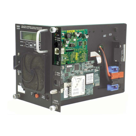
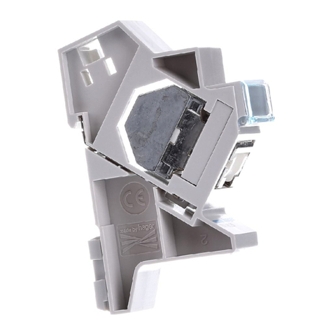
Sole Digital TrafficLite TFL200 User manual

TRAFFICLITE EXPANSION MODULE
Model TFL200, Version 2
Installation and User Manual
Revision 01 –January 2019
© CASWA Pty Ltd –2018

© CASWA Pty Ltd –2014 2 | Page
CONTENTS
1OVERVIEW............................................................................................................................3
2SPECIFICATIONS....................................................................................................................3
2.1 Physical Specifications ............................................................................................................3
2.2 Electrical Specifications...........................................................................................................4
3INSTALLATION DETAILS.........................................................................................................4
3.1 Prior to Installation .................................................................................................................4
3.2 Wiring Diagrams......................................................................................................................5
4COMMISSIONING DETAILS ....................................................................................................5
4.1 Setting set points ....................................................................................................................6
4.1.1 Setting up for traffic light display.............................................................................6
4.1.2 Setting up for high speed limiting............................................................................6
4.1.3 Setting up for slack rope detection..........................................................................7
4.2 The Status LEDS.......................................................................................................................8

© CASWA Pty Ltd –2014 3 | Page
1OVERVIEW
TrafficLite is an add-on module for Liftlog and MaxOut and provides 3 additional output relays. It can
be used for controlling traffic lights, limiting high speed motion at high loads, and slack rope
detection. Nb, TrafficLite REQUIRES a MaxOutDX, or LiftlogDX to work, it has no load sensing functions.
2SPECIFICATIONS
2.1 Physical Specifications
Overall length (mm):
115
Overall width (mm):
100
Overall height (mm):
23
Weight (kg):
0.12
Mounting:
30mm DIN Rail
Figure 1: Case Dimensions

© CASWA Pty Ltd –2014 4 | Page
2.2 Electrical Specifications
Parameter
Description
Min
Typ
Max
Units
Vin
Supply voltage
24
250
VAC
Iin
Supply current
7
8
12
mA
Vfault
Max voltage for switch output
250
V AC
Ifault
Max current sink by switch output
4
A
Pfault
Max contactor inrush rating at 48V
200
W
Allowable operating temperature
-40
85Note1
°C
Note1: Extended operation at maximum temperature will reduce the life the device.
3INSTALLATION DETAILS
3.1 Prior to Installation
Before installing your TrafficLite device visually inspect the device and check that:
(a) the case is not damaged and fits together securely;
(b) terminals are secure;
(c) terminal numbering is as per the following diagram.
Figure 2: Terminal Positions

© CASWA Pty Ltd –2014 5 | Page
3.2 Wiring Diagrams
TrafficLite should be installed next to the MaxOut or Liftlog that will be controlling it. The maximum
length of cable between the units should not exceed 200mm
Figure 3: Connecting to Liftlog or MaxOut
4COMMISSIONING DETAILS
TrafficLite is set up when you configure the Liftlog or MaxOut that it is connected to. See the
LiftlogDX and MaxOutDX manuals for details on installing the software to do this.

© CASWA Pty Ltd –2014 6 | Page
4.1 Setting set points
On the configuration screen there are three configurable set points.
Figure 4: Set points
Enter the load for each set point in Kg or Lb and set the swtich to be normally open or closed.
4.1.1 Setting up for traffic light display
For switching indicator lights (or sirens) the switches should be configured normally open. The
contacts of the units are voltage free (floating) and can switch the high or low side of the circuit.
Figure 5: Settings for indicator lights
4.1.2 Setting up for high speed limiting
Typically one of the relays will be wired in series with the fast contactor for the up motion of the
crane and set to normally closed.

© CASWA Pty Ltd –2014 7 | Page
Figure 6: Settings for speed limiting
In this example the high speed function would drop out at 9000Kg
4.1.3 Setting up for slack rope detection
Connect one of the relays in series with the control signal to the down contactor and set the set
point to 0Kg
Figure 7: Settings for slack rope detection
Nb for slack rope detection to work reliably the unit must see at least a 5% change in load when the
rope goes slack. For a 10t crane this means the hook block, hook and any lifting fixture must weigh a
MINIMUM of 500Kg. If you try to implement slack rope detection with a normal light duty hook
block then you can be 100% sure that you will end up with an angry customer who can’t lower the
hook. In practice, slack rope detection requires additional load in the form of a lifting jig, or dead
weight added to the crane.
When implementing slack rope detection the zero load for the MaxOut or Liftlog should always be
taken with the hook at the top limit. If you don’t do this then the Liflog or MaxOut will see the load
decrease as the hook is raised because the rope is being wound onto the drum. If this causes the
load to drop below the set point then the operator will be unable to lower the hook.

© CASWA Pty Ltd –2014 8 | Page
4.2 The Status LEDS
Your TrafficLite has three indicators on the front panel. Each indicates the status of each output.
Colour
Status
RED
Communications error
GREEN
CLOSED
BLUE
OPEN
Table of contents
