SOLE AIRSOL User manual

GB
EL
GB
AIR COLLECTORS ’’AIRSOL’’
INSTALLATION AND USER MANUAL
MODELS: AIRSOL 10, AIRSOL 20 &
AIRSOL 35

Page2
INDEX
PAGE
1. Presentation ……………………………………………………………………..
3
2. Introduction ...............................................................................................
5
3. Parts Included ……………………………………………………………………
5
3.1. Solar Collectors …………………………………………………………….
5
4. Installation …………………………………………………….........................
6
4.1. Flat roof vertical installation................................................................
7
4.2 Flat roof horizontal installation ………………………...........................
8
4.3 Wall mounting installation………….....................................................
9
5. Recirculation ……………………………………………................................
10
6. Air Filter ………………………………………………………………...............
11
7. Summer Season ……………………………………………..........................
11
8. Room Thermostat....................………………………………………………..
12
9. General instructions ................................................................................
13
10. Care and Maintenance Program ...........................................................
13

Page3
1. Presentation
The solar air collector AIRSOL heats air that flows inside the room area with the help of an
integrated fan.
The fan operates with solar photovoltaic panels that are also built into the unit. For big industrial
projects the AIRSOL 35, is also available without PV and fan.
The device can take fresh air from the ambient OR recirculated air from the heated room. It is also
possible for the user to adjust it to partially recirculated air with a supplement of fresh air.
In any case the air is filtered before is heated and flows into room space.
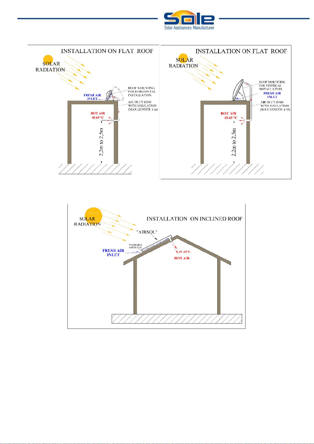
The AIRSOL can be installed on a South or Southeast or Southwest wall (for the northern
hemishpere) (see drawing 1, 1a &1b) or on a terrace (see drawings 2& 3) or on a tile roof (see
drawing 4).
For the AIRSOL 10 & 20 you will need a duct of Ø100 diameter of proportional length and similar
grille, for the AIRSOL 35 a duct of Ø200 diameter will be needed.
DRAWING 1
DRAWING 1b
DRAWING 1a
Page4
DRAWING 2 DRAWING 3
DRAWING 4
Page5
2. Introduction
The present document demonstrates detailed installation instructions for the solar collectors using
the support frames and accessories included in the supply.
Before proceeding with the installation of the collectors, read these instructions and make sure you
have understood. If you have questions about the materials or on the assembly process described
in this document, contact your supplier via telephone, fax or e-mail. Improper installation of the
collectors may cause an unsatisfactory operation of the solar system, compromising its durability
and even be dangerous for the people or the goods.
The instructions of this document do not exempt in any way the compliance with existing
regulations and provisions of technical and administrative application at the place where the facility
is located.
The installation of solar collectors without following the instructions in this document and / or
regulations will invalidate the warranty of the product.
The installer will check before starting the installation that he has all the necessary parts and all the
security measures have been taken in order to carry out the installation safely. The installer must
use protective gloves to avoid any risk of burns or cuts during handling of collectors or its support
frame.
3. Parts Included
The supply consists of:
One or more solar collectors
One or more support frames
One or more fitting and accessories.
3.1. Solar Collectors
3.1.1. Models
3.1.2. Packaging
The solar air collectors are supplied individually packaged in carton boxes. The collector model is
indicated on the outside of each box. Depending on the number of units ordered, collectors can be
supplied palletised in groups of up to 7 units.
TYPE
DIMENSIONS (mm)
SURFACE
m²
NOMINAL VALUE**
RECOMMENDED
FOR ROOM AREA
AIRSOL 10
1545x700x178
1,08
700Wp
10 to 40 m²
AIRSOL 20
2050x1040x195
2,13
1500Wp
20 to 60 m²
AIRSOL 35
2833x1285x140
3,65
2700Wp
35 to100 m²

Page6
4. Installation
The support frames sets are composed of elements that are shown in Figures 1 & 2.
Figure 1
Figure 2
Page7
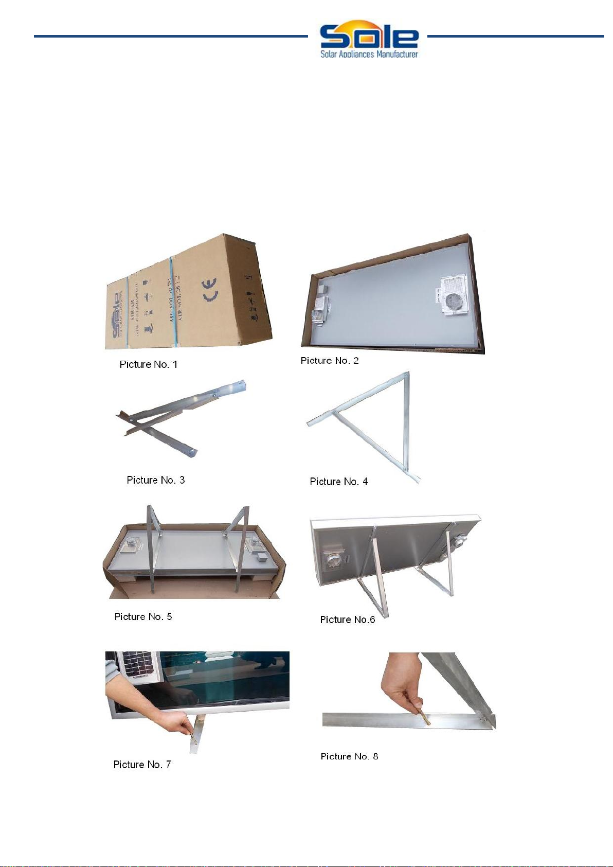
4.1. Flat Roof Horizontal Installation
Take off the cover of the carton box and remove the polystyrene protections (see pictures no. 1 &
2).The support frame consists of two triangles frames, partly preassembled. Screw the profiles A
and C with the bolts and nuts provided and tighten.(see picture no. 4).
Fix part B of the triangle frame on the corresponding nuts on the collector (see picture 5) and
tighten with bolts M6.
Lift the collector and join the structure to the floor, placing the collector in operation position and fit it
using the raw plugs and anchored bolts supplied on the flat roof (see pictures 7 & 8).
A
B
C
B
A
C
B
B
C
A
B
Page8
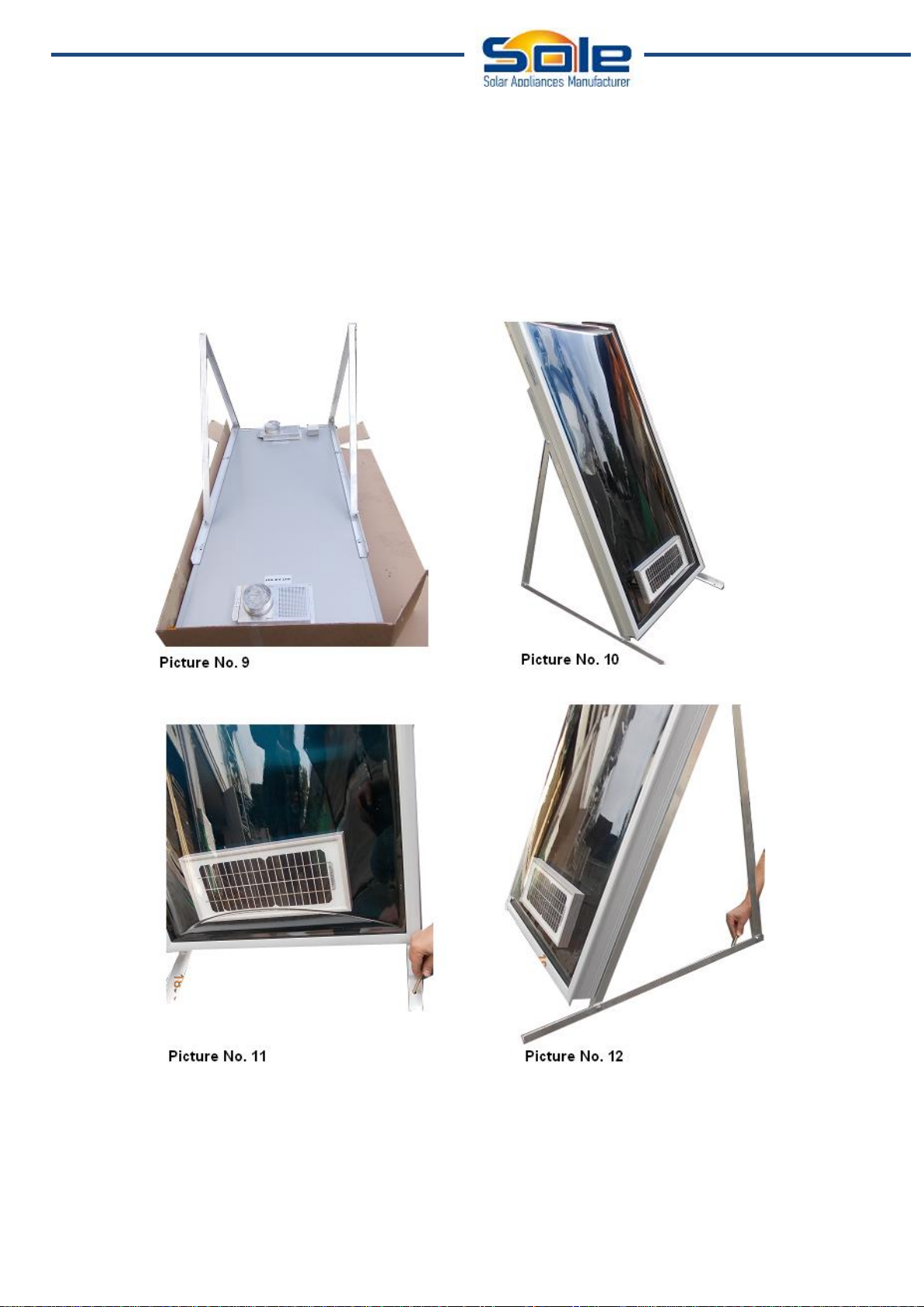
4.2. Flat Roof Vertical Installation
The assembly of solar air collectors on a flat roof in vertical position is done in a manner similar to
that described above; with different size of the support triangles frame placed vertically in a parallel
manner on the back of the collector (see picture 9).
Lift the collector and join the structure to the floor, placing the collector in operation position and fit it
using the raw plugs and anchored bolts supplied on the flat roof (see pictures 11-12).
Page9
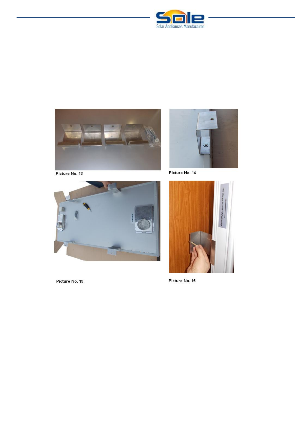
4.3. Wall Mounting Installation
Take off the cover the carton box and remove the polystyrene protections (see picture no.1).The
support frame consists of 4 stainless steel mounting brackets. Fix the 4 mounting brackets on the
corresponding nuts on the collector (see picture no.13) and tighten with bolts M6 (see picture no.
14 & 15)
Lift the collector and join the structure to the wall using the raw plugs and anchored bolts (see
picture no. 16).

Page10
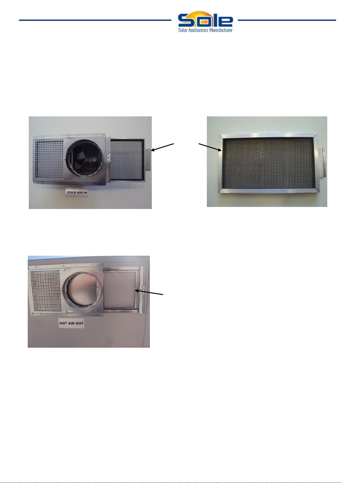
5. Recirculation
In case of installation with recirculation (see drawing 1b), the sliding entrance door of ‘’COLD AIR
IN’’ must be ‘’INSIDE’’.
SLIDING DOOR ‘’INSIDE’’
For a 100% fresh air the sliding door must be ‘’OUT’’.
SLIDING DOOR ‘’OUT’’
For recirculation 50% and fresh air 50% the sliding door of ‘’COLD AIR IN’’ must be in the
‘’MIDDLE’’.
SLIDING DOOR MUST BE IN THE ‘’MIDDLE’’
Page11
6. Air Filter
At regular intervals depending on the purity of the environment but not more than 6 months, remove
by hand the sliding filter, wash it with cold water to the tap by turning it from both sides and when it
dries put it in its place.
The purity of the filter is important for clean air and for the good performance of the device.
FILTER
7. Summer Season
The season that the heating is not needed, place the sliding door of the HOT AIR OUT at the
‘’OUT’’ position.
SLIDING DOOR OF ‘’HOT AIR OUT’’ AT THE OUT
POSITION
In this position the hot air does not flow in the house but outdoors.
If we have recirculation then we can succeed ventilation of the area since the device sucks air from
the inside of the room.
Alternatively, if you have purchased the optional cover, you can cover the entire device.

Page12
8. Room Thermostat
Optionally a thermostat can be connected on the AIRSOL in order to control the device from the
room.
In case you want to connect the thermostat follow the procedure below:
Step 1
Open the cover of the electrical box at the back side of the collector.
Step 2
Disconnect the bypass cable from the cable connector.
Step 3
Connect to the cable connector the silicone cable from and to the thermostat.
Step 4
Close the cover of the electrical box.
Step 5
Connect the other end of the red silicone cable, following the schematic diagram that you will find at
the electric box on the back of the collector.

Page13
9. General Instructions
The device delivers air into the room from 35º to 40º C higher than the entrance temperature in
good sunshine and with the correct orientation. So, if it sucks 100% fresh air at 0º C temperature
the warm air extracted in room will be about 35º C to 40º C. If the temperature of fresh air is 10ºC
the warm air extracted in space will be at a temperature of 45º to 50º C.
If we have installation with recirculation and sucks air of 20º C temperature, then the warm air will
be extracted in space about 55º to 60º C.
The air collectors AIRSOL 10 & AIRSOL 20 are intended for either cottage houses or warehouses,
or for permanent residence, office or other space.
For cottage house or warehouse the main target is to maintain the room slightly warm and dry while
the air is renewed so that we avoid the smell of closure and mold. In this case the AIRSOL 10 is
sufficient for a room up to 30-40m² and the AIRSOL 20 is sufficinet for a room of 40-60m² and the
AIRSOL 35 is sufficient for a room of 50-80m². The installation with a 100% fresh air is
recommended.
For permanent residence or office or any other place the target is to save energy for heating on
winter. So, for savings from 50% to 80% and more the AIRSOL 10 is suffiecient for space 10-20m²
and the AIRSOL 20 for space 20-30m² and the AIRSOL 35 for space 30-40m².
10. Care and Maintenance Program
• The collectors should be subject to periodic visual inspections. If it appears that excessive dirt has
been accumulated on the transparent cover of the collectors, then it must be cleaned. This
operation should take place during the morning, before 10:00 am or in the afternoon after the 18:00
pm, checking before that the collectors are not too hot. Otherwise, there might be a risk of
damaging the collector, (especially when using a hose),
• If for some reason the collector’s cover breaks, it should be replaced immediately. Otherwise, the
interior of the collector may deteriorate due to rain, humidity or dirt.
• The support of solar collector is made of aluminium profile. As a precaution, verify the fixations to
the tile or flat roof.
• Early in the morning, before starting the operation, condensation of humidity contained in the air
will be deposited on the inside of the transparent cover. This is a normal procedure and it will
disappear after the device starts working.
• Clean the air filter periodically as mentioned in paragraph 6 (Air-filter).

Page14
Published: February 2013
Version 3
SOLE S.A.
SOLAR DOMESTIC APPLIANCES MANUFACTURER
Lefktron & Laikon Agonon, 136 71 Acharnai – Athens – Greece
Tel.: (+30210) 2389500 • Fax: (30210) 2389502
Email: expor[email protected] • www.eurostar-solar.com
This manual suits for next models
3
Table of contents


