WIKA CPT2500 User manual

WIKA Alexander Wiegand SE & Co. KG
Alexander-Wiegand-Straße 30
63911 Klingenberg/Germany
Phone (+49) 9372/132-9986
Fax (+49) 9372/132-8767
E-Mail testequip@wika.de
www.wika.de
Druckmessumformer CPT2500 mit USB-Adapter CPA2500 und USBsoft
V2.2 07/2011
Pressure sensor CPT2500 with USB adapter CPA2500 and USBsoft
GB
Instruction manual
Bedienungsanleitung
D

Pressure sensor CPT2500 with USB adapter CPA2500 and USBsoft
WIKA Operating Instructions, model CPT2500
2
Index
1GENERAL .......................................................................................................................................3
1.1 Software Operation....................................................................................................................3
1.2 Software License Agreement.....................................................................................................3
1.3 Safety regulations......................................................................................................................4
1.4 System Requirements ...............................................................................................................4
2GENERAL HANDLING INSTRUCTIONS........................................................................................5
2.1 Operation mode.........................................................................................................................5
2.2 To connect / change sensors.....................................................................................................5
2.3 Zero correction of the pressure sensor ('OFFS')........................................................................5
2.4 Slope correction of the pressure sensor ('SCAL').......................................................................5
2.5 Pressure connection to the pressure sensor..............................................................................5
2.6 Advice for calibration service.....................................................................................................6
3DRIVER INSTALLATION ................................................................................................................6
3.1 Windows 2000, Windows XP, Windows Vista Windows 7 ...............................................6
4FREQUENTLY ASKED QUESTIONS (FAQ)...................................................................................6
4.1 How to check, whether the adapter has been installed correctly and via which COM-port can I
approach the installed adapter?..................................................................................................6
4.2 How to change the COM-port of the adapter? ...........................................................................6
4.3 Is there an automatic update function that updates the installed driver to the latest version?.....6
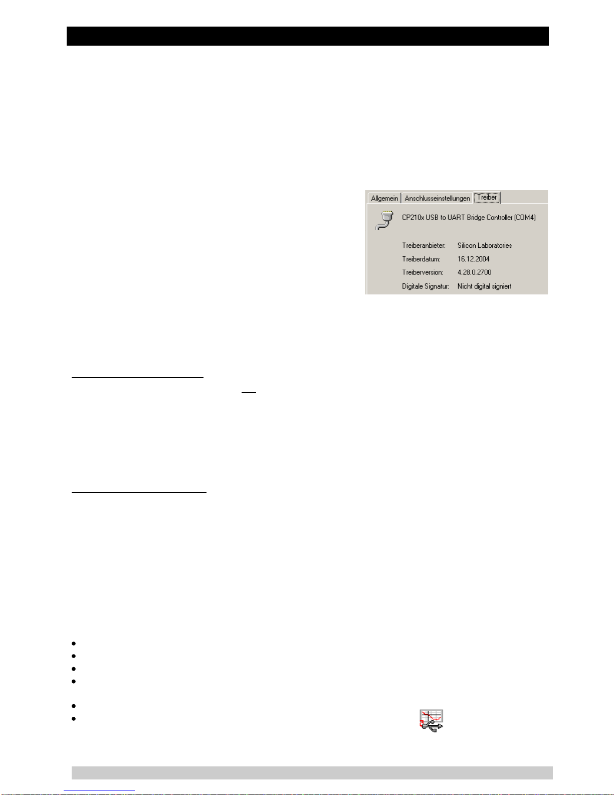
4.4 How to find out the used version of the driver?..........................................................................7
4.5 How to update a driver of an older version or how to uninstall the driver?..................................7
5OPERATING SOFTWARE USBSOFT2500.....................................................................................7
5.1 Software Installation ..................................................................................................................7
5.2 Screen Elements.......................................................................................................................8
5.2.1 Menu bar.............................................................................................................................8
5.2.2 Toolbar................................................................................................................................8
5.3 Data Recording..........................................................................................................................8
5.3.1 Connecting the USB-Adapter..............................................................................................8
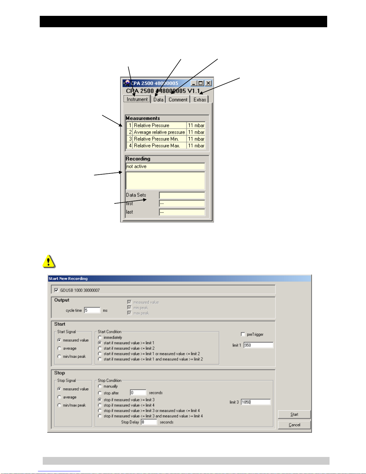
5.3.2 Sensor Data Screen............................................................................................................9
5.3.3 Start Recording...................................................................................................................9
5.3.4 Displaying the Measurements...........................................................................................10
5.3.5 Stop Recording .................................................................................................................10
5.3.6 Comment ..........................................................................................................................11
5.3.7 Extras................................................................................................................................11
5.4 File Operation..........................................................................................................................11
5.5 Print Data ................................................................................................................................12
5.6 Measurement Diagrams ..........................................................................................................12
5.6.1 Adding Data Labels...........................................................................................................13
5.6.2 Adding Series....................................................................................................................13
5.6.3 Zoom-function...................................................................................................................13
5.6.4 Copying Data to Clipboard................................................................................................13
6SPECIFICATION ...........................................................................................................................14
7DISPOSAL INSTRUCTIONS.........................................................................................................15

Pressure sensor CPT2500 with USB adapter CPA2500 and USBsoft
WIKA Operating Instructions, model CPT2500
3
1 General
The CPA2500-adaptor makes it possible to connect a pressure sensor model CPT2500 directly to the
USB-port of a personal computer. The associated Software USBsoft2500 allows to conduct the moni-
toring settings and to display the measuring data automatically in the adjusted cycle time. This mode is
especially adapted for the analysis of pressure curves and the survey of pressure peaks (with pre-
trigger).
1.1 Software Operation
This operating manual postulates basic knowledge of how to handle a personal computer with the op-
er
introductory courses etc.).
1.2 Software License Agreement
The subject matter of the contract is the programs, operating instructions and miscellaneous appertain-
ing material recorded on CD-ROM.
As a registered user you shall be permitted:
to use the copy of the program contained on a single computer.
to produce a backup copy. The copyright note of WIKA shall have
to be attached to this backup copy.
As a registered user you shall be not permitted:
to hand-over to a third party or to make accessible to a third party
the program without prior written approval of WIKA.
to install the program in any form on a multi-user system.
to copy in whole or in part (with the exception of the backup copy), to modify, to translate, to back
develop, to decompile, to disassemble or to decode the program as well as to set up derived vari-
ants from the program.
By purchasing the program you shall only obtain ownership in the CD-ROMs, on which the program is
recorded. The ownership in the rights of the program proper shall not be obtained. All rights to publica-
tion, duplication, processing and exploitation of the program shall remain with WIKA.
WIKA guarantees that the CD-ROM on which the program was recorded is free from defects in material
under normal operating conditions. If the data carriers have a defect, the said can be returned to WIKA
within a period of thirty days after the date of first purchase. The CD-ROMs will be replaced immediate-
ly free of charge.
WIKA guarantees that the program is operational within the keeping of the program description. As it is
not possible at the present state of the art to produce computer programs in such a way that they work
without faults in all applications and combinations, WIKA shall not assume any liability for faultlessness
and the uninterrupted operation of the program. No guarantee shall be given in particular for the fact
that the program meets the requirements of the user or for the fact that the program operates together
with the program selected. The responsibility for the correct selection and the consequences of the use
of the program as well as for the results intended or obtained shall be borne by the buyer (registered
user).
WIKA shall not be liable for any damage, expect for damage which has been caused by gross negli-
gence on the side of WIKA. In this case WIKA shall assume liability for direct injury or property damage
up to ten times the purchase price for each event of damage. WIKA shall not be held liable for any
damage other than the said rendered above. The liability for gross negligence shall be excluded vis-à-
vis merchants.
This contract shall be in force until the registered user terminates it by destroying the program inclusive
of all copies. In addition, the contract shall terminate in case of a violation of these contractual stipula-
tions. The registered user shall be obligated to destroy the program and all copies at the termination of
the contract.

Pressure sensor CPT2500 with USB adapter CPA2500 and USBsoft
WIKA Operating Instructions, model CPT2500
4
WIKA wish to point out that the registered user shall be liable for all damage caused by the violation of
the copyrights which occur to WIKA from the violation of these contractual stipulations by the registered
user.
1.3 Safety regulations
This device was designed and tested considering the safety regulations for electronic measuring devic-
es. Faultless operation and reliability in operation of the measuring device can only be assured if the
General Safety Measures and the devices specific safety regulation mentioned in this operating instruc-
tion are considered.
1. Warning: Open pressure connections only after the system is without pressure!
2. Warning: Please make sure that the pressure sensor is only used within the overpressure safety
limit!
3. EMC advice: Do not connect a cable that exceeds a length of 3 m.
4. Safety advice: Have repairs performed by the manufacturer only.
5. Faultless operation and reliability in operation of the measuring device can only be assured if the
6. By faulty handling of the interface adapter a damage of the device cannot be excluded. Likewise a
damage of your attached device is possible. In such case we cannot assume any warranty.
The manufacturer will not assume any warranty for damages to other devices resulting by use of the
interface adapter.
7. Standard regulations for operation and safety for electrical, light and heavy current equipment have
to be observed, with particular attention paid to the national safety regulations (e.g. VDE 0100).
8. When connecting the device to other devices (e.g. the PC) the interconnection has to be designed
most thoroughly, as internal connections in third-party devices (e.g. connection of ground with pro-
tective earth) may lead to undesired voltage potentials.
9. The device must be switched off and must be marked against using again, in case of obvious mal-
functions of the device which are e.g.:
- visible damage
- no prescribed working of the device
- storing the device under inappropriate conditions for longer time
When not sure, the device should be sent to the manufacturer for repairing or servicing.
10. Warning: Do NOT use this product as safety or emergency stopping device or in any other applica-
tions, where failure of the product could result in personal injury or material damage.
Failure to comply with these instructions could result in serious injury and material dam-
age
1.4 System Requirements
At least 20 MB hard disk capacity available
CD-ROM drive
At least 256 MB main memory
Mouse
One unassigned USB-port

Pressure sensor CPT2500 with USB adapter CPA2500 and USBsoft
WIKA Operating Instructions, model CPT2500
5
2 General handling instructions
2.1 Operation mode
The measurement is started by a trigger condition. Then the device automatically gives back the meas-
ured values in the adjusted cycle time without any request, until the stop condition is fulfilled. For the
communication and configuration of the device, the software USBSoft2500 is necessary.
Adjustable parameters are among other ones:
Cycle time: 1ms ... 10sec., programmable in steps of ms
Measured values:
cycle time < 5 ms it is possible to choose the values to be recorded
(measurand, min. peak, max. peak)
cycle time > 5 ms a complete data set is always recorded, containing the following values:
- actual pressure at the moment of the data transfer
- minimum pressure (min. peak) in the period of the last cycle time
- maximum pressure (max. peak) in the period of the last cycle time
- average value of the pressure in the period of the last cycle time
Trigger conditions: 5 for the measuring start / 6 for the measuring stop
Pre-trigger: 50 data sets (at a cycle time of 5ms) respectively 200 measurands (cycle
time < 5 ms)
2.2 To connect / change sensors
Only pressure sensor model CPT2500 are allowed to be used! If other sensors are used the adapter and
the sensor may be destroyed.
To change the sensor you have to disconnect the adapter. Sensors have to be connected before acti-
vating the adapter. Otherwise they are not found by the adapter correctly.
During the connecting it is possible that the connector does not snap in the jack correctly. In this case you
have to hold the connector at the bend relief not at the casing. Don`t plug the connector wedged. An accu-
rate attached jack can be easily plugged in without great effort. To disconnect the sensors it is not allowed
to pull at the cable. In this case you have to hold the connector at its casing.
2.3 Zero correction of the pressure sensor ('OFFS')
For the measurement a zero offset can be conducted:
shown vale = measured value - offset
The zero correction in combination with the slope correction (see below) is mainly used to adjust the devi-
ation of sensors. The entry has to be made in the configuration software. The offset information will be
stored in the sensor. So you can set it individually for each sensor.
2.4 Slope correction of the pressure sensor ('SCAL')
The measurement`s slope can be affected by this factor (factor in %):
shown value = measured value * (1 + scale / 100)
The slope correction in combination with the zero correction (see above), are mainly used to adjust the
deviation of sensors. The entry has to be made in the configuration software. The scale information will be
stored in the sensor. So you can set it individually for each sensor.
2.5 Pressure connection to the pressure sensor
The measuring adapter is conceived that way, that all sensors of the CPT2500-series can be connected
without new calibration. Therefore a multiplicity of fully exchangeable sensors for metering ranges of
-1 ... 0 bar relative to 0 ... 1000 bar absolute are available.
For overpressure, low-pressure or absolute pressure measurements: screw the sensor in the threat
(G1/2

Pressure sensor CPT2500 with USB adapter CPA2500 and USBsoft
WIKA Operating Instructions, model CPT2500
6
2.6 Advice for calibration service
Factory calibration certificate DKD-certificate ministerial certifications:
If the measuring device shall have a calibration certificate you have to send it inclusive the sensor to the
manufacturer. Just the manufacturer can check the factory settings and correct them if necessary.
3 Driver Installation
3.1 Windows 2000, Windows XP, Windows Vista™and Windows 7
For installation of the device drivers a user account with an administrator-authorisation is re-
quired. If you haven’t an appropriate authorisation please consult your system administrator.
- Insert driver disk into the drive of your PC
- Start the installer CP210XVCPInstaller.exe from drive.
- Follow the instructions of the install wizard
- Plug in the USB-plug connector of the CPA2500 into the USB-connection of your PC
- Now the CPA2500 will be installed automatically with the actual driver.
Now the CPA2500 is installed on your system and available for all users.
For application with our software a new additional COM-Port is available. (quod vide chapter 6)
4 Frequently asked questions (FAQ)
4.1 How to check, whether the adapter has been installed correctly and via which
COM-port can I approach the installed adapter?
Start the Device-Manager (Win XP: click start \ (settings) \ control panel \ performance and maintenance \
system \
If the CP210X USB to UART Bridge Controller (COM
x)-port (i.e. COM 4).
Note: The adapter will not be shown in the device manager, if it is not connected to the PC.
If the entry is occupied by an exclamation mark or the entry is not there, then the driver has not been
installed correctly.
4.2 How to change the COM-port of the adapter?
Make sure that the adapter is connected, start the Device-Manager (Win XP: click start \ (settings) \ con-
trol panel \ performance and maintenance \ system \
. CP210X USB to UART Bridge Controller
(COM x) x after the Com indicates the available COM-port (i.e. COM 4).
Open the features of this connection by a double-
There you can choose the preferred COM- e-
served for another (even not connected) device, an error message will appear. In principle it is possible
that 2 devices are set on the same COM-port, but then you have to take care, that not both devices are
connected at the same time, because this would lead to a conflict.
4.3 Is there an automatic update function that updates the installed driver to the lat-
est version?
The driver is not updated automatically.
If there is already a suitable (for the operating system) driver during the installation, this driver will be used
automatically.
If the usage of the adapter cause problems, please make sure that the latest version of the driver for the
adapter is used and install the latest version manually (see 6.5) if necessary.

Pressure sensor CPT2500 with USB adapter CPA2500 and USBsoft
WIKA Operating Instructions, model CPT2500
7
4.4 How to find out the used version of the driver?
Two device drivers are needed to use the adapter. Firstly the “USB-Composite Device” (for the USB-
device) and the “USB to UART Bridge Controller” (for the supply of the COM-port).
Make sure that the adapter is connected and start the Device-Manager ( Win XP: click start \ (settings) \
control panel \ performance and maintenance \ system \ hardware).
For the USB---Manager, open the features
for thiCP210X USB Composite Device-
For the COM-
CP210X
USB to UART Bridge Controller (COM x)double-
There you can see the
currently used driver version.
4.5 How to update a driver of an older version or how to uninstall the driver?
In order to update the driver, you have to uninstall the “old“ driver first and install the latest driver after-
wards.
1) Uninstallation of the driver
- Make sure that the USB-adapter is not connected.
- Go to start \ (settings) \ control panel and then double-
- CP210X USB to UART Bridge Controller
- -up window.
- The driver will now be uninstalled.
Thus the driver is uninstalled for all corresponding USB-adapters.
2) Reinstallation of the driver:
The reinstallation is just the same as an installation the first time. Please re
for installing the new driver.
5 Operating Software USBsoft2500
USBsoft2500 permits the handling of an USB measuring adapter of the CPA2500 series. This adapter
enables a direct connection of a pressure sensor type CPT2500 to the USB-interface of a personal
computer. With this dedicated software it is possible to start, stop, read in and display recordings. For
visualisation and for a better overview the recorded data can be shown in diagrams.
5.1 Software Installation
Insert CD-ROM in CD-ROM drive
\- D stands for the letter of your CD-ROM drive press the return key. In case your
CD-
Follow the instructions given by the installation program.
A new program group with the following program icon will be created:
The software will be started by double clicking on this symbol.

Pressure sensor CPT2500 with USB adapter CPA2500 and USBsoft
WIKA Operating Instructions, model CPT2500
8
Start program, choose the language you desire and the interface to which you have connected your
interface adapter.
5.2 Screen Elements
5.2.1 Menu bar
You can easily have access to all software functions by using the menu bar. The content of the menu
bar depends on the program status:
5.2.2 Toolbar
To ensure comfortable software operation the most important software functions have been put togeth-
er at the Toolbar. Moving the mouse pointer over a symbol shows a short description of the function.
The content of the toolbar depends on the program status:
1.1 1.2 1.3 2.1 2.2 2.3 3.1 4.1 4.2
File functions:
1.1 open file
1.2 save file
1.3 print file
Sensor functions:
2.1 connect USB-measuring adapter
2.2 start new recording
2.3 stop recording
Data representation:
3.1 create new diagram
Further functions:
4.1 interface configuration
4.2 program information
5.3 Data Recording
5.3.1 Connecting the USB-Adapter
connect the USB measuring adapter to the USB-Port
toolbar.
USBsoft2500 is now searching for connected measuring devices.
The located measuring adapter will be shown like this:
-port will be initialised and
attached devices will be located. Should still no measuring adapter be found please check the following
points again:
Is the USB measuring adapter connected to the USB-port?

Pressure sensor CPT2500 with USB adapter CPA2500 and USBsoft
WIKA Operating Instructions, model CPT2500
9
5.3.2 Sensor Data Screen
measurements table
current status of the re-
cording;
start-/stop-condition
number of data sets and
period of recording
5.3.3 Start Recording
When recordings are restarted, all data which have been recorded before will be delet-
ed!! If necessary read in and save important information or save the data or demand be-
fore a measurement-restart!

Pressure sensor CPT2500 with USB adapter CPA2500 and USBsoft
WIKA Operating Instructions, model CPT2500
10
To start a new
symbol.
Now you can choose from an assortment of start and stop conditions and define the output data.
Choice of the recording mode:
Output: Cycle time: here you can decide in which intervals measuring points should be recorded. At
the same time you can select which value will be displayed (measured value, min/max peak).
Please note: at a cycle time of more or equal than 5ms all measured values will be selected automati-
cally. A direct selection is no longer possible.
Start: e-
lected the measuring will start directly after starting it. At the other conditions you have to define one or
more thresholds (if these are under- or overrun the condition depending on the selected case is fulfilled
or not). The thresholds` entry is carried out in the mask on the right side. You even can select which
signal shall cause the measuring start. But this is only available when the cycle time is higher or equal
The preTrigger makes it possible for you to detect values before the normal values measured (after the
start condition).
too.
At a cycle time of less than 5ms, 200 measured values are possible.
At a cycle time more or equal than 5ms 50 data sets are possible, which are made up of four different
series of measurements (50 data sets x 4 series of measurements = 200 measuring values).
Example: a cycle time of 10ms is selected. There will be 10ms long 50 data sets (=500ms) recorded
before the normal measuring will be started.
Stop: Here it is possible, in analogy to the start conditions, to set the stop conditions. Besides the man-
ual stop and the measuring stop after a certain time, the stop by specified thresholds is available, too (if
these are under- or overrun the condition depending on the selected case is fulfilled or not). The
thresholds` entry is carried out in the mask on the right side. You even can select which signal shall
cause the measuring stop. But this is only available when the cycle time is higher or equal than 5ms.
The Stop Delay effects a continuous measurement until the defined time is up. After this the measuring
will be stopped automatically.
5.3.4 Displaying the Measurements
To read the measuring values the cyclic recording has to be stopped first.
The white fields for the table heading can be edited.
If
5.3.5 Stop Recording
If a recording is stopped, data are preserved which have been received until that moment.

Pressure sensor CPT2500 with USB adapter CPA2500 and USBsoft
WIKA Operating Instructions, model CPT2500
11
5.3.6 Comment
As soon as the data have been read you may enter your com-
ments here. If data are saved as a file, the comment will also
be saved in the same file automatically.
Furthermore there is the possibility to load recurrent comments
in form of a template.
To do so, enter a suitable text-file (only .txt-format!) via button
manually to the window.
previously selected text file is loaded automatically, whenever
data is read out.
The comment can be edited afterwards as usual.
m-
m-
ment, when a new record is started.
5.3.7 Extras
This register permits adjustment options for the recording.
If necessary, Offset and Scale can be corrected.
The low pass filter provides the possibility for suppressing pressure
peaks.
5.4 File Operation
For
Export Files
The data files can be saved as ASCII (=text) file to view them for example in word processing or in a
spread sheet
attention particularly at spread sheets to make right settings in the following pop-up win-
dow.

Pressure sensor CPT2500 with USB adapter CPA2500 and USBsoft
WIKA Operating Instructions, model CPT2500
12
5.5 Print Data
The respectively selected window
(data or diagram) can be printed via
printer has been installed to your
to change printer parameters or to
choose another printer.
er
or footer pictures can be integrated to
the printouts.
The pictures or other templates have
to be saved as .bmp, .jpg or .icon
format (By this feature picture size
must matched before). The printout
can be extended to an individual form by simple means.
5.6 Measurement Diagrams
The loaded data of the measuring windows can also be displayed in diagrams.
The diagram will be opened.
System limitations: - maximum 2 different units (mbar, bar, etc.) per diagram
- maximum 15 graphs per unit
Y-axis: displays the unit
Legend:if activated a
description of the graph
will be displayed
Add / delete series:
the number of dis-
played graphs can be
changed (see below)
Settings:
manual zoom,
grid and colour
settings
Zoom back:
cancels last zoom
action
Zoom all:
show max.
diagram area
Display points:
display (marking) of
measuring points
Change name: the diagram (here:
Cursor: if activated a crosshair cursor will be displayed to
show the individual measuring points. The measuring point
data will be displayed in the status bar
Scrollbar: if a
zooming action
has been carried
out the scrollbar
can be used to
diagram
Zoom left/right Y-axis:
choose here if the mouse
zoom function is to be ap-
plied to the left or right Y-
axis
Add / delete labels: measuring
points can be described (see below)

Pressure sensor CPT2500 with USB adapter CPA2500 and USBsoft
WIKA Operating Instructions, model CPT2500
13
5.6.1 Adding Data Labels
the corresponding symbol. By moving the mouse over the diagram the symbol will appear as mouse
pointer. A text line which can be filled in freely will be placed at the position desired by a mouse click.
5.6.2 Adding Series
the diagram window. The data source selection will ap-
pear again and you can select additional measuring series.
5.6.3 Zoom-function
If 2 units are displayed: use the and symbols to select the Y-axis desired.
Place the mouse at the beginning of the desired area, hold the left mouse key, move the mouse to the
end of the desired area and release the mouse key: the selected part will be enlarged (zoomed).
The enlarged view can be moved left, right, up and down with the scrollbar. To show accurate display
number and time declaration.
5.6.4 Copying Data to Clipboard
Diagrams can be copied to the clipboard, to insert them in other applications again:
Click on the required diagram and press the key combination Strg + C -> the diagram will be copied to
the clipboard as a bitmap.

Pressure sensor CPT2500 with USB adapter CPA2500 and USBsoft
WIKA Operating Instructions, model CPT2500
14
6 Specification

Pressure sensor CPT2500 with USB adapter CPA2500 and USBsoft
WIKA Operating Instructions, model CPT2500
15
CE conformity CPT2500
Pressure equipment
directive: 97/23/EC, module A, pressure accessory
EMC directive: 2004/108/EC, EN 61326 Emission (Group 1, Class B) and Immunity
(commercial area, i.e. workshops, laboratories or service centres)
CE conformity CPA2500
EMC directive: 2004/108/EC, EN 61326 Emission (Group 1, Class B) and Immunity
(controlled electromagnetic environment)
This equipment is designed for operation in a controlled electromagnetic environment, e.g. test or laboratory envi-
ronments. RF transmitters such as mobile telephones may not be used in close proximity.
7 Disposal instructions
The device must not be disposed in the regular domestic waste.
Send the device directly to us (sufficiently stamped), if it should be disposed. We will dispose the
device appropriate and environmentally sound.

WIKA Betriebsanleitung Druckmessumformer
16
Druckmessumformer CPT2500 mit USB-Adapter CPA2500
Inhaltsverzeichnis
1ALLGEMEIN..................................................................................................................................17
1.1 Bedienung der Software..........................................................................................................17
1.2 Softwarelizenzvereinbarung.....................................................................................................17
1.3 Sicherheitshinweise.................................................................................................................18
1.4 Systemvoraussetzungen .........................................................................................................18
2ALLGEMEINE BETRIEBSHINWEISE...........................................................................................19
2.1 Betriebsmodus.........................................................................................................................19
2.2 Sensoren anstecken / wechseln ..............................................................................................19
2.3 Nullpunktkorrektur des Drucksensor ('OFFS')..........................................................................19
2.4 Steigungskorrektur des Drucksensor ('SCAL').........................................................................19
2.5 Druckanschluss an die Drucksensoren....................................................................................20
2.6 Hinweis zum Kalibrierservice...................................................................................................20
3TREIBER-INSTALLATION............................................................................................................20
3.1 Windows 2000, Windows XP und Windows Vistabzw. Windows 7......................................20
4HÄUFIG GESTELLTE FRAGEN (FAQ).........................................................................................20
4.1 Wie kann ich überprüfen, ob der Adapter korrekt installiert wurde und unter welchem COM-Port
kann ich den neu installierten Adapter nun ansprechen?..........................................................20
4.2 Wie kann ich den COM-Port des Adapters ändern? ................................................................20
4.3 Wird ein älterer, bereits im System vorhandener, Treiber automatisch aktualisiert? ................21
4.4 Wie kann ich die verwendete Treiberversion feststellen?.........................................................21
4.5 Wie kann ich eine ältere Treiberversion aktualisieren bzw. deinstallieren?..............................21
5DIE SOFTWARE USBSOFT2500..................................................................................................22
5.1 Installation der Software..........................................................................................................22
5.2 Bedienelemente.......................................................................................................................22
5.2.1 Menüleiste.........................................................................................................................22
5.2.2 Werkzeugleiste..................................................................................................................22
5.3 Datenaufzeichnung..................................................................................................................23
5.3.1 USB-Adapter verbinden ....................................................................................................23
5.3.2 Sensor-Datenfenster.........................................................................................................23
5.3.3 Aufzeichnung starten.........................................................................................................23
5.3.4 Auslesen der Messwerte...................................................................................................25
5.3.5 Aufzeichnung stoppen.......................................................................................................25
5.3.6 Kommentar hinzufügen / Textvorlagen einbinden..............................................................25
5.3.7 Extras................................................................................................................................25
5.4 Arbeiten mit Dateien................................................................................................................26
5.4.1 Dateien exportieren...........................................................................................................26
5.4.2 Daten in die Zwischenablage kopieren..............................................................................26
5.5 Daten drucken.........................................................................................................................26
5.6 Messwertdiagramme ...............................................................................................................27
5.6.1 Datenbeschriftungen hinzufügen.......................................................................................27
5.6.2 Messreihen hinzufügen.....................................................................................................27
5.6.3 ...................................................................28
5.6.4 Diagramme in die Zwischenablage kopieren.....................................................................28
6TECHNISCHE DATEN ..................................................................................................................29
7ENTSORGUNGSHINWEISE .........................................................................................................30

Druckmessumformer CPT2500 mit USB-Adapter CPA2500 und USBsoft
WIKA Betriebsanleitung Druckmessumformer
17
1 Allgemein
Der USB-Adapter CPA2500 ermöglicht die direkte Anbindung eines Druckmessumformers Typ
CPT2500 an die USB-Schnittstelle eines PCs.
Mit Hilfe der zugehörigen Bedien- und Auslesesoftware USBsoft2500 können die Einstellungen für das
Aufzeichnen von Messwerten des Druckmessumformers CPT2500 vorgenommen werden. Weiterhin
können die aufgezeichneten Messwerte graphisch dargestellt und analysiert werden.
1.1 Bedienung der Software
Diese Bedienungsanleitung setzt Grundkenntnisse in der Bedienung eines PCs unter dem Betriebssys-
a-
machen (Handbücher, Fachliteratur, Einführungs-
kurse etc.)
1.2 Softwarelizenzvereinbarung
Als Lizenznehmer sind Sie berechtigt, die enthaltene Kopie des Programms auf einem oder mehreren
Computern zu nutzen, sowie eine Sicherungskopie anzufertigen. Dabei ist auf der Sicherungskopie der
Urheberrecht-Vermerk von WIKA anzubringen.
Als Lizenznehmer ist Ihnen untersagt, das Programm ganz oder teilweise abzuändern, zu übersetzen,
zurückentwickeln, zu dekompilieren, zu entassemblieren oder zu decodieren, sowie von dem Pro-
gramm abgeleitete Werke zu erstellen.
Sie erhalten mit dem Erwerb des Programmes nur das Eigentum an den CD-Roms, auf denen das
Programm aufgezeichnet ist. Ein Erwerb an Rechten des Programmes selbst ist damit nicht verbunden.
Alle Rechte zur Veröffentlichung, Vervielfältigung, Bearbeitung und Verwertung des Programmes ver-
bleiben bei WIKA.
WIKA gewährleistet, dass die CDs, auf denen das Programm aufgezeichnet ist, unter normalen Be-
triebsbedingungen in Materialausführung einwandfrei sind. Sollten die Datenträger einen Fehler auf-
weisen, so können innerhalb einer Frist von 30 Tagen ab Datum des Ersterwerbs, die Datenträger an
WIKA eingeschickt werden. Die CD-Roms werden umgehend kostenlos ersetzt.
WIKA gewährleistet, dass das Programm im Sinne der Programmbeschreibung grundsätzlich brauch-
bar ist. Da es nach dem Stand der Technik nicht möglich ist, Computerprogramme so zu erstellen, dass
sie in allen Anwendungen und Kombinationen fehlerfrei arbeiten, übernimmt WIKA keine Haftung für
die Fehlerfreiheit und den ununterbrochenen Betrieb des Programmes. Insbesondere wird keine Ge-
währ dafür übernommen, dass das Programm den Anforderungen des Anwenders entspricht oder mit
anderen von ihm ausgewählten Programmen zusammenarbeitet. Die Verantwortung für die richtige
Auswahl und die Folgen der Benutzung des Programmes, sowie der damit beabsichtigten oder erziel-
ten Ergebnisse trägt der Käufer (Lizenznehmer).
WIKA haftet nicht für Schäden, außer der Schaden wurde durch grobe Fahrlässigkeit seitens WIKA
verursacht. In diesem Falle haftet WIKA für unmittelbare Personen- oder Sachschäden pro Schadens-
fall bis zum Zehnfachen des Kaufpreises. Für andere als die vorgenannten Schäden haftet WIKA nicht.
Gegenüber Kaufleuten wird die Haftung für grobe Fahrlässigkeit ausgeschlossen.
Dieser Vertrag ist in Kraft, bis der Lizenznehmer ihn durch Vernichtung des Programmes samt allen
Kopien beendet. Darüber hinaus erlischt er bei Verstoß gegen die Vertragsbedingungen. Der Lizenz-
nehmer verpflichtet sich, bei Vertragsbeendigung das Programm und alle Kopien zu vernichten.
WIKA ist berechtigt, Verbesserungen und Weiterentwicklungen des Programmes nach eigenem Er-
messen durchzuführen

Druckmessumformer CPT2500 mit USB-Adapter CPA2500 und USBsoft
WIKA Betriebsanleitung Druckmessumformer
18
WIKA macht darauf aufmerksam, dass der Lizenznehmer für alle Schäden aufgrund von Urheber-
rechtsverletzungen haftet, die WIKA aus einer Verletzung dieser Vertragsbestimmungen durch den
Lizenznehmer entstehen.
Durch das Öffnen der Verpackung erklären Sie sich mit den Vereinbarungen einverstanden.
1.3 Sicherheitshinweise
Dieses Gerät ist gemäß den Sicherheitsbestimmungen für elektronische Messgeräte gebaut und geprüft.
Die einwandfreie Funktion und Betriebssicherheit des Gerätes kann nur dann gewährleistet werden,
wenn bei der Benutzung die allgemein üblichen Sicherheitsvorkehrungen sowie die gerätespezifischen
Sicherheitshinweise in dieser Bedienungsanleitung beachtet werden.
1. Warnung: Öffnen Sie Anschlüsse nur im drucklosen Zustand!
2. Warnung: Betreiben Sie das Druckmessgerät immer innerhalb des Überlastgrenzbereichs!
3. EMV-Hinweis: Keine Leitungen anschließen, die länger als 3 m sind.
4. Sicherheits-Hinweis: Lassen Sie Reparaturen nur vom Hersteller durchführen.
5. Die einwandfreie Funktion und Betriebssicherheit des Gerätes kann nur unter den klimatischen Ver-
6. Bei unsachgemäßer Handhabung des Schnittstellenadapters kann dieser selbst beschädigt werden.
Ebenso ist es möglich, dass Ihre angeschlossenen Geräte geschädigt werden.
In diesem Fall besteht kein Garantieanspruch.
Der Hersteller übernimmt keinerlei Haftung für Schäden, die an ihren angeschlossenen Geräten
durch den Einsatz des Schnittstellenadapters verursacht werden.
7. Beachten Sie die üblichen Vorschriften und Sicherheitsbestimmungen für Elektro-, Schwach- und
Starkstromanlagen, insbesondere die landesüblichen Sicherheitsbestimmungen (z.B. VDE 0100).
8. Konzipieren Sie die Beschaltung besonders sorgfältig beim Anschluss an andere Geräte (z. B. PC).
Unter Umständen können interne Verbindungen in Fremdgeräten (z. B. Verbindung GND mit
Schutzerde) zu nicht erlaubten Spannungspotenzialen führen.
9. Wenn anzunehmen ist, dass das Gerät nicht mehr gefahrlos betrieben werden kann, so ist es außer
Betrieb zu setzen und vor einer weiteren Inbetriebnahme durch Kennzeichnung zu sichern.
Die Sicherheit des Benutzers kann durch das Gerät beeinträchtigt sein, wenn es zum Beispiel:
- sichtbare Schäden aufweist
- nicht mehr wie vorgeschrieben arbeitet
- längere Zeit unter ungeeigneten Bedingungen gelagert wurde
In Zweifelsfällen sollte das Gerät grundsätzlich an den Hersteller zur Reparatur / Wartung einge-
schickt werden.
10. Achtung: Dieses Gerät ist nicht für Sicherheitsanwendungen, Not-Aus Vorrichtungen oder An-
wendungen bei denen eine Fehlfunktion Verletzungen und materiellen Schaden hervor-
rufen könnte, geeignet. Wird dieser Hinweis nicht beachtet, könnten schwere gesund-
heitliche und materielle Schäden auftreten.
1.4 Systemvoraussetzungen
Mind. 20 MB freier Festplattenspeicher
CD-ROM Laufwerk
Mind. 256 MB Arbeitsspeicher
Maus
Einen freien USB-Port

Druckmessumformer CPT2500 mit USB-Adapter CPA2500 und USBsoft
WIKA Betriebsanleitung Druckmessumformer
19
2 Allgemeine Betriebshinweise
2.1 Betriebsmodus
Mit Hilfe der zugehörigen Software USBsoft2500 wird der Messumformer konfiguriert und die Messwer-
te aufgezeichnet.
Einstellbare Parameter sind hierbei unter anderem:
Zykluszeit: 1 ms ... 10 sec., programmierbar in ms-Schritten
Messwerte:
Zykluszeit < 5 ms es kann der aufzuzeichnende Wert (Messwert, min. Peak, max. Peak) gewählt
werden.
Zykluszeit > 5 ms es wird immer ein vollständiger Datensatz aufgezeichnet, der die folgenden
Messwerte enthält:
- aktueller Druck zum Zeitpunkt der Datenübertragung
- Minimaldruck (min. Peak) im Zeitraum der letzten Zykluszeit
- Maximaldruck (max. Peak) im Zeitraum der letzten Zykluszeit
- Mittelwert des Druckes über den Zeitraum der letzten Zykluszeit
Triggerbedingungen: 5 für Aufzeichnungsstart
6 für Aufzeichnungsstopp
Pre-Trigger : 50 Datensätze (bei Zykluszeit > 5 ms) bzw. 200 Messwerte (Zykluszeit < 5 ms)
Die Messung wird mittels einer Triggerbedingung gestartet und das Gerät gibt dann automatisch, ohne
weitere Aufforderung, in der eingestellten Zykluszeit die Messwerte aus, bis die Stopp-Bedingung erfüllt
ist.
2.2 Sensoren anstecken / wechseln
In Verbindung mit dem USB-Adapter CPA2500 dürfen nur Druckmessumformer vom Typ CPT2500
verwendet werden! Mit anderen Sensoren kann es zur Zerstörung des Adapters und des Sensors
kommen.
Zum Sensorwechsel ist der Adapter abzustecken. Sensoren vor dem Aktiveren des Adapters anstecken,
sonst wird er vom Adapter evtl. nicht richtig erkannt.
Beim Anstecken kann es vorkommen, dass der Stecker nicht richtig in die Buchse einrastet. In diesem
Fall den Stecker beim Anstecken nicht an der Steckerhülse sondern am Knickschutz halten. Stecker nicht
verkantet anstecken. Bei richtig angesetztem Stecker kann dieser ohne größeren Kraftaufwand einge-
steckt werden. Beim Abstecken der Sensoren nicht am Kabel ziehen, sondern nur an der Steckerhülse.
2.3 Nullpunktkorrektur des Drucksensor ('OFFS')
Für die Messung kann eine Nullpunktverschiebung vorgenommen werden:
angezeigter Wert = gemessener Wert –Offset
Die Nullpunktkorrektur wird zusammen mit der Steigungskorrektur (s.u.) vor allem zum Abgleich von Sen-
sorabweichungen verwendet. Die Eingabe erfolgt in der Konfigurationssoftware. Die Offset-Information
wird im Sensor gespeichert, kann also für jeden Sensor getrennt durchgeführt werden.
2.4 Steigungskorrektur des Drucksensor ('SCAL')
Die Steigung der Messung kann mit diesem Faktor beeinflusst werden (Faktor ist in %):
angezeigter Wert = gemessener Wert * (1 + Scale / 100)
Die Steigungskorrektur wird zusammen mit der Nullpunktkorrektur (s.o.) vor allem zum Abgleich von Sen-
sorabweichungen verwendet. Die Eingabe erfolgt in der Konfigurationssoftware. Die Scale-Information
wird im Sensor gespeichert, kann also für jeden Sensor getrennt durchgeführt werden.

Druckmessumformer CPT2500 mit USB-Adapter CPA2500 und USBsoft
WIKA Betriebsanleitung Druckmessumformer
20
2.5 Druckanschluss an die Drucksensoren
Der Messadapter ist so konzipiert, dass alle Druckmessumformer vom Typ CPT2500 ohne Neuabgleich
angesteckt werden können. Somit stehen Ihnen eine Vielzahl austauschbarer Sensoren mit Messberei-
chen von 1 ... 0 bar bis 0 ... 1000.0 bar absolut zur Aus-
wahl.
Für Überdruck- bzw. Absolutdruckmessungen: Sensor in Gewinde (G1/2") einschrauben oder Kunststoff-
schlauch über passenden Adapter an Drucksensor anstecken.
2.6 Hinweis zum Kalibrierservice
Werkskalibrierschein DKD-Schein amtliche Bescheinigungen:
Soll das Messgerät einen Kalibrierschein erhalten, ist dieses mit dem zugehörigen Fühler zum Hersteller
einzuschicken. Nur der Hersteller kann die Einstellungen überprüfen und wenn notwendig korrigieren.
3 Treiber-Installation
3.1 Windows 2000, Windows XP und Windows Vista™bzw. Windows 7
Für die Installation der Gerätetreiber ist ein Benutzerkonto mit Administrator-Rechten erforder-
lich. Sollten Sie diese Rechte nicht besitzen, so melden Sie sich mit einem entsprechenden Kon-
to an oder fragen Sie Ihren Systemadministrator.
- Legen Sie den Datenträger mit dem Treiber in Ihr Laufwerk ein.
- Starten Sie nun entsprechend Ihres Betriebssystems den Installer für den Treiber vom Datenträger:
CP210XVCPInstaller.exe
- Folgen Sie nun den Anweisungen des Installationsprogrammes
-Stecken Sie den CPA2500 an den USB-Anschluss Ihres PCs an.
- Der CPA2500 wird nun automatisch mit dem aktuellen Treiber installiert.
Der CPA2500 ist nun auf Ihrem System installiert und steht damit allen Benutzern zur Verfügung.
Für die Verwendung mit der Software USBsoft2500 steht Ihnen nun ein weiterer COM-Port zur Verfü-
gung. (siehe auch Kapitel 4)
4 Häufig gestellte Fragen (FAQ)
4.1 Wie kann ich überprüfen, ob der Adapter korrekt installiert wurde und unter wel-
chem COM-Port kann ich den neu installierten Adapter nun ansprechen?
Rufen Sie unter Start \ (Einstellungen) \ Systemsteuerung \ System \ Hardware den Gerätemanager auf
.
CP210X USB to UART Bridge Controller (COM x)
wobei das x nach dem COM für den nun verfügbaren COM-Port steht (z.B. COM 4).
Hinweis: Damit der Adapter im Gerätemanager angezeigt wird muss er am PC angesteckt sein!
Sollte der Eintrag mit einem Ausrufezeichen versehen sein oder nicht enthalten sein, so wurde der Treiber
nicht korrekt installiert.
4.2 Wie kann ich den COM-Port des Adapters ändern?
Rufen Sie, bei angestecktem Adapter, unter Start \ (Einstellungen) \ Systemsteuerung \ System \ Hard-
CP210X USB to UART Bridge Controller (COM x)
wobei das x nach dem COM für den derzeit verwendeten COM-Port steht (z.B. COM 4).
Other manuals for CPT2500
1
This manual suits for next models
1
Table of contents
Languages:
Other WIKA Accessories manuals
Popular Accessories manuals by other brands

CMA Dishmachines
CMA Dishmachines DIFFERENTIALVOLTAGE SENSORBT32i user guide

Sygonix
Sygonix 2390079 operating instructions

Allen-Bradley
Allen-Bradley 45BPD-8LTB1-D5 installation instructions

Woodstock
Woodstock G2370 instruction manual

Thule
Thule Rain Blocker G2 instructions

Trident
Trident PLUS user manual