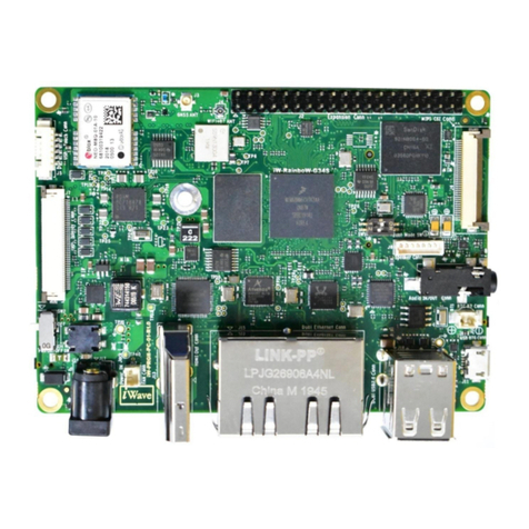
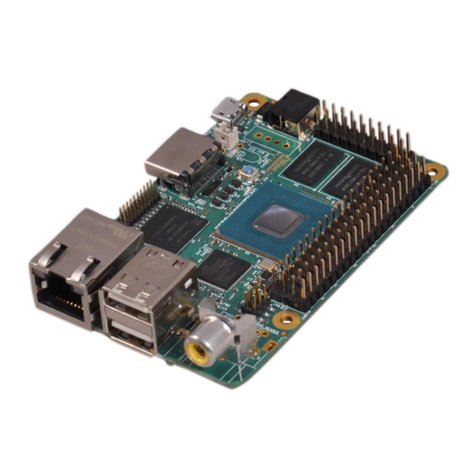
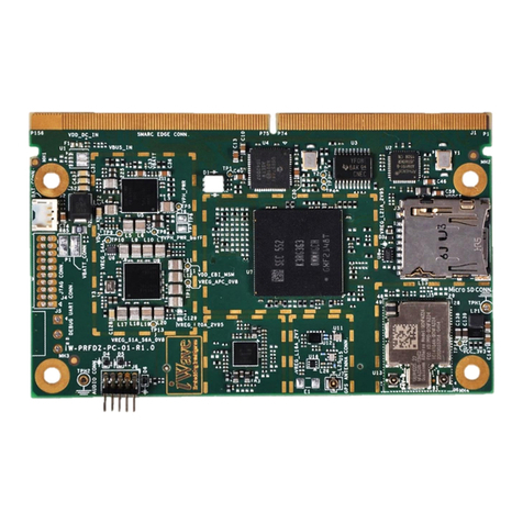
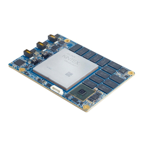
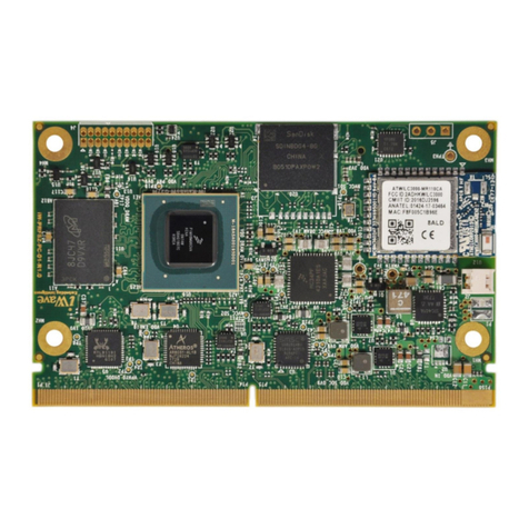
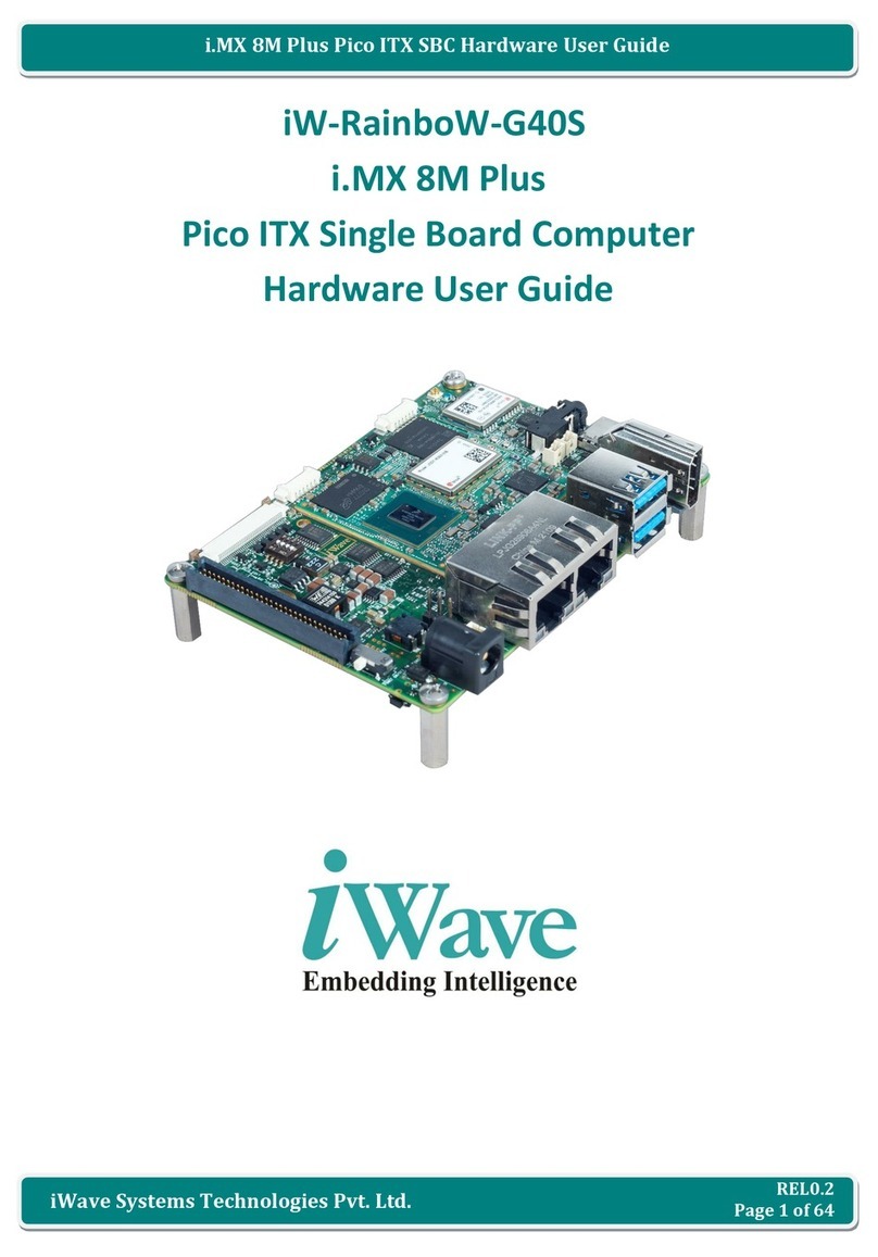
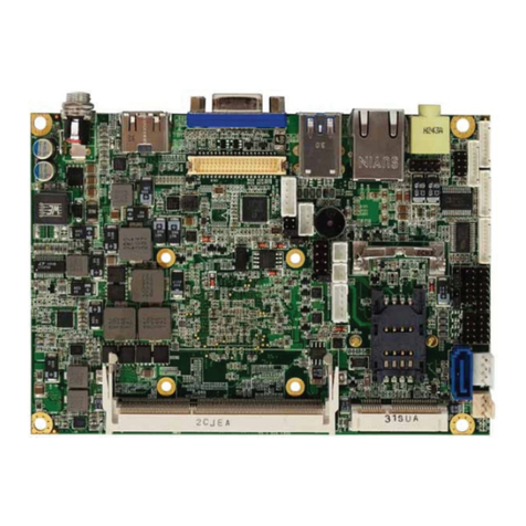
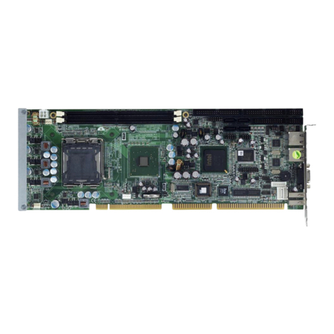
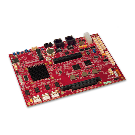
iWave iW-RainboW-G15M-SM Installation manual

REL 1.2
Page 1 of 56
i.MX6 SODIMM SOM Hardware User Guide
iWave Systems Technologies Pvt. Ltd.
iW-RainboW-G15M-SM
i.MX6 SODIMM System On Module
Hardware User Guide

REL 1.2
Page 2 of 56
i.MX6 SODIMM SOM Hardware User Guide
iWave Systems Technologies Pvt. Ltd.
Document Revision History
Document Number
iW-PREPZ-UM-01-R3.0-REL1.2-Hardware
Revision
Date
Description
1.0
29th Dec 2014
Initial Release Version
1.1
18th Jul 2016
Updated version - Substantive changes done throughout the document
1.2
03rd Mar 2017
Updated version
Pins 179, 189, 194, 196 & 200 details are updated in Table 5
Section 2.6.22 is newly added
Section 3.3.1 is updated.
Table 11 Orderable Product Part Numbers are updated
Non-Substantive changes done throughout the document
PROPRIETARY NOTICE: This document contains proprietary material for the sole use of the intended recipient(s). Do
not read this document if you are not the intended recipient. Any review, use, distribution or disclosure by others is
strictly prohibited. If you are not the intended recipient (or authorized to receive for the recipient), you are hereby
notified that any disclosure, copying distribution or use of any of the information contained within this document is
STRICTLY PROHIBITED. Thank you. “iWave Systems Tech. Pvt. Ltd.”

REL 1.2
Page 3 of 56
i.MX6 SODIMM SOM Hardware User Guide
iWave Systems Technologies Pvt. Ltd.
Disclaimer
iWave Systems reserves the right to change details in this publication including but not limited to any Product
specification without notice.
No warranty of accuracy is given concerning the contents of the information contained in this publication. To the
extent permitted by law no liability (including liability to any person by reason of negligence) will be accepted by
iWave Systems, its subsidiaries or employees for any direct or indirect loss or damage caused by omissions from or
inaccuracies in this document.
CPU and other major components used in this product may have several silicon errata associated with it. Under no
circumstances, iWave Systems shall be liable for the silicon errata and associated issues.
Trademarks
All registered trademarks, product names mentioned in this publication are the property of their respective owners
and used for identification purposes only.
Certification
iWave Systems Technologies Pvt. Ltd. is an ISO 9001:2015 Certified Company.
Warranty & RMA
Warranty support for Hardware: 1 Year from iWave or iWave's EMS partner.
For warranty terms, go through the below web link,
http://www.iwavesystems.com/support/warranty.html
For Return Merchandise Authorization (RMA), go through the below web link,
http://www.iwavesystems.com/support/rma.html
Technical Support
iWave Systems technical support team is committed to provide the best possible support for our customers so that
our Hardware and Software can be easily migrated and used.
For assistance, contact our Technical Support team at,
Email : support.ip@iwavesystems.com
Website : www.iwavesystems.com
Address : iWave Systems Technologies Pvt. Ltd.
# 7/B, 29th Main, BTM Layout 2nd Stage,
Bangalore, Karnataka,
India –560076

REL 1.2
Page 4 of 56
i.MX6 SODIMM SOM Hardware User Guide
iWave Systems Technologies Pvt. Ltd.
Table of Contents
1. INTRODUCTION ............................................................................................................................................7
1.1 Purpose .............................................................................................................................................................7
1.2 SODIMM SOM Overview................................................................................................................................... 7
1.3 List of Acronyms................................................................................................................................................7
1.4 Terminlogy Description.....................................................................................................................................9
1.5 References ........................................................................................................................................................9
1.6 Important Note ...............................................................................................................................................10
2. ARCHITECTURE AND DESIGN....................................................................................................................... 11
2.1 i.MX6 SODIMM SOM Block Diagram...............................................................................................................11
2.2 i.MX6 SODIMM SOM Features........................................................................................................................12
2.3 i.MX6 CPU .......................................................................................................................................................14
2.4 PMIC................................................................................................................................................................15
2.5 Memory...........................................................................................................................................................15
2.5.1 DDR3 SDRAM ..............................................................................................................................................15
2.5.2 SPI NOR Flash ..............................................................................................................................................15
2.5.3 eMMC Flash ................................................................................................................................................15
2.6 i.MX6 SODIMM PCB Edge Connector..............................................................................................................16
2.6.1 Boot Setting.................................................................................................................................................17
2.6.2 Gigabit Ethernet..........................................................................................................................................18
2.6.3 PCIe Interface ..............................................................................................................................................18
2.6.4 SATA Interface.............................................................................................................................................19
2.6.5 USB2.0 OTG Interface..................................................................................................................................19
2.6.6 USB2.0 Host Interface .................................................................................................................................19
2.6.7 SD Interface.................................................................................................................................................19
2.6.8 Parallel Camera Interface............................................................................................................................20
2.6.9 Parallel RGB Display Interface.....................................................................................................................20
2.6.10 LVDS Interface.............................................................................................................................................20
2.6.11 HDMI Interface............................................................................................................................................21
2.6.12 I2S Audio Interface ......................................................................................................................................21
2.6.13 UART Interface ............................................................................................................................................22
2.6.14 SPI Interface ................................................................................................................................................22
2.6.15 CAN Interface ..............................................................................................................................................22
2.6.16 I2C Interface................................................................................................................................................23
2.6.17 PWM Interface ............................................................................................................................................23
2.6.18 GPIO Interface.............................................................................................................................................23
2.6.19 JTAG Interface .............................................................................................................................................23
2.6.20 Power Input.................................................................................................................................................24
2.6.21 Reset Button Input ......................................................................................................................................24
2.6.22 Power Button Input .....................................................................................................................................24
2.7 i.MX6 Pin Multiplexing on SODIMM Edge ......................................................................................................36
3. TECHNICAL SPECIFICATION.......................................................................................................................... 47

REL 1.2
Page 5 of 56
i.MX6 SODIMM SOM Hardware User Guide
iWave Systems Technologies Pvt. Ltd.
3.1 Electrical Characteristics .................................................................................................................................47
3.1.1 Power Input Requirement ...........................................................................................................................47
3.1.2 Power Input Sequencing..............................................................................................................................48
3.1.3 Power Consumption ....................................................................................................................................49
3.2 Environmental Characteristics ........................................................................................................................50
3.2.1 Environmental Specification........................................................................................................................50
3.2.2 RoHS Compliance ........................................................................................................................................50
3.2.3 Electrostatic Discharge................................................................................................................................50
3.3 Mechanical Characteristics .............................................................................................................................51
3.3.1 i.MX6 SODIMM SOM Mechanical Dimensions............................................................................................51
4. ORDERING INFORMATION .......................................................................................................................... 52
5. APPENDIX I................................................................................................................................................. 54
5.1 Guidelines to insert the SODIMM SOM into Carrier board ............................................................................54
5.2 Guidelines to remove the SODIMM SOM from Carrier board........................................................................54
6. APPENDIX II................................................................................................................................................ 55
6.1 i.MX6 SODIMM SOM Development Platform.................................................................................................55

REL 1.2
Page 6 of 56
i.MX6 SODIMM SOM Hardware User Guide
iWave Systems Technologies Pvt. Ltd.
List of Figures
Figure 1: i.MX6 SODIMM SOM Block Diagram................................................................................................................11
Figure 2: i.MX6 Simplified Block Diagram.......................................................................................................................14
Figure 3: i.MX6 SODIMM PCB Edge Connector...............................................................................................................16
Figure 4: i.MX6 SODIMM SOM Power Sequence............................................................................................................48
Figure 5: Mechanical dimension of i.MX6 SODIMM SOM - Top View............................................................................51
Figure 6: Mechanical dimension of i.MX6 SODIMM SOM - Side View ...........................................................................51
Figure 7: Module Insertion Procedure............................................................................................................................54
Figure 8: Module Removal Procedure ............................................................................................................................54
Figure 9: i.MX6 SODIMM SOM Development Platform..................................................................................................55
List of Tables
Table 1: Acronyms & Abbreviations.................................................................................................................................. 7
Table 2: Terminology ........................................................................................................................................................9
Table 3: Boot Mode Pin Settings Truth Table .................................................................................................................17
Table 4: Compatible Magnetics ......................................................................................................................................18
Table 5: 200-Pin PCB Edge Connector Pin Assignment...................................................................................................25
Table 6: IOMUX Configuration of i.MX6 SODIMM SOM Edge Connector interfaces .....................................................36
Table 7: Power Input Requirement.................................................................................................................................47
Table 8: Power Sequence Timing....................................................................................................................................48
Table 9: Power Consumption..........................................................................................................................................49
Table 10: Environmental Specification ...........................................................................................................................50
Table 11: Orderable Product Part Numbers ...................................................................................................................52

REL 1.2
Page 7 of 56
i.MX6 SODIMM SOM Hardware User Guide
iWave Systems Technologies Pvt. Ltd.
1. INTRODUCTION
1.1 Purpose
This document is the Hardware User Guide for the i.MX6 SODIMM System On Module based on the NXP’s i.MX6
Applications Processor with PMIC. This board is fully supported by iWave Systems Technologies Pvt. Ltd. This Guide
provides detailed information on the overall design and usage of the i.MX6 SODIMM System On Module from a
Hardware Systems perspective.
1.2 SODIMM SOM Overview
The i.MX6 SODIMM SOM is extension of i.MX6 CPU. Also with the SOM approach one can reduce the cost and time
required for the development of customised solution on i.MX6 SODIMM platform. SODIMM module has a form
factor of 67.6mm x 37mm and provides the functional requirements for an embedded application. A single
ruggedized SODIMM connector provides the carrier board interface to carry all the I/O signals to and from the
SODIMM module.
1.3 List of Acronyms
The following acronyms will be used throughout this document.
Table 1: Acronyms & Abbreviations
Acronyms
Abbreviations
ARM
Advanced RISC Machine
BPP
Bits Per Pixel
BSP
Board Support Package
CAN
Controller Area Network
CMOS
Complementary Metal-Oxide Semiconductor
CPU
Central Processing Unit
CSI
Camera Serial Interface
DDR3
Double Data Rate 3
eCSPI
Enhanced Configurable Serial Peripheral Interface
eMMC
Enhanced Multi Media Card
FLEXCAN
Flexible Controller Area Network
GB
Giga Byte
Gbps
Gigabits per sec
GPIO
General Purpose Input Output
HDMI
High Definition Multimedia Interface
I2C
Inter-Integrated Circuit
IC
Integrated Circuit
JTAG
Joint Test Action Group
Kbps
Kilobits per second

REL 1.2
Page 8 of 56
i.MX6 SODIMM SOM Hardware User Guide
iWave Systems Technologies Pvt. Ltd.
Acronyms
Abbreviations
LCD
Liquid Crystal Display
LVDS
Low Voltage Differential Signal
MAC
Media Access Controller
MB
Mega Byte
Mbps
Megabits per sec
MHz
Mega Hertz
NC
No Connect
PCB
Printed Circuit Board
PCIe
Peripheral Component Interface Express
PMIC
Power Management Integrated Circuit
PWM
Pulse Width Modulation
RTC
Real Time Clock
SAI
Synchronous Audio Interface
SD
Secure Digital
SDRAM
Synchronous Dynamic Random Access Memory
SOM
System On Module
SODIMM
Small Outline Dual in-line Memory Module
UART
Universal Asynchronous Receiver/Transmitter
USB
Universal Serial Bus
USB OTG
USB On The Go

REL 1.2
Page 9 of 56
i.MX6 SODIMM SOM Hardware User Guide
iWave Systems Technologies Pvt. Ltd.
1.4 Terminlogy Description
In this document, wherever Signal Type is mentioned, below terminology is used.
Table 2: Terminology
Terminology
Description
I
Input Signal
O
Output Signal
IO
Bidirectional Input/output Signal
CMOS
Complementary Metal Oxide Semiconductor Signal
DIFF
Differential Signal
OD
Open Drain Signal
OC
Open Collector Signal
Power
Power Pin
PU
Pull Up
PD
Pull Down
NA
Not Applicable
NC
Not Connected
Note: Signal Type does not include internal pull-ups or pull-downs implemented by the chip vendors and only includes
the pull-ups or pull-downs implemented On-SOM.
1.5 References
i.MX6 Applications Processors Datasheet
i.MX6 Applications Processors Reference Manual

REL 1.2
Page 10 of 56
i.MX6 SODIMM SOM Hardware User Guide
iWave Systems Technologies Pvt. Ltd.
1.6 Important Note
i.MX6 SODIMM Edge connector pin name mentioned in Table 5 is followed as per below format for easy
understanding.
If CPU pin functionality name and CPU pad name is same, Signal name is mentioned as
“CPU Pad Name”
Example: SD1_DATA1
In this signal, functionality which we are using and CPU Pad name is SD1_DATA1.
If CPU pin functionality name and pad name is different, Signal name is mentioned as
“Functionality name (CPU Pad name)”
Example: CAN1_RXD (UART3_RTS_B)
In this signal, CAN1_RXD is the functionality which we are using and UART3_RTS_B is the CPU Pad name.
If CPU pin functionality is GPIO, Signal name is mentioned as
“FunctionalityDescription (CPU Pad name)”
Example: PWM4_OUT (GPIO1_IO05)
In this signal, PWM4_OUT is the functionality which we are using and GPIO1_IO05 is the CPU pad name.
Note: The above naming is not applicable for other signals which are not connected to CPU.

REL 1.2
Page 11 of 56
i.MX6 SODIMM SOM Hardware User Guide
iWave Systems Technologies Pvt. Ltd.
2. ARCHITECTURE AND DESIGN
This section provides detailed information about the i.MX6 SODIMM SOM Features and Hardware architecture with
high level block diagram. Also this section provides detailed information about SODIMM edge connector pin
assignment and usage.
2.1 i.MX6 SODIMM SOM Block Diagram
iW-RainboW-G15M-SM -i.MX6 SODIMM SOM Block Diagram
CPU
i.MX6x
DDR3 RAM
(1GB)
SPI Flash
(2MB)
eMMC
(4GB)
SODIMM
PCB Edge
Connector
(200Pin)
USB Host x 1
USBOTG x 1
I2C x 2
USB OTG
HS PHY
USB HOST1
HS PHY
MMC (8bit)
SPI
MMDC
eCSPI1
uSDHC4
I2S x 1
AUDMUX4
UART2
DISP0
SJC
JTAG
Power to
Peripherals
3.3V
Debug
HDMI 1.4
PMIC
RGB LCD (24bpp)
HDMI
UART1
UART4
UART5
UART3x 3
LVDS
LVDS0
CSI0
Camera(8bit)3
1Solo CPU supports only 32bit DDR3 interface.
2SATA interface is not supported in i.MX6
Duallite and Solo CPU.
3If Parallel camera interface is used, then two
data UART interfaces (UART4 & UART5)
cannot be used with hardware flow control
signals on SODIMM edge.
DDR31(64bit)
eCSPI2
CAN1,CAN2 CAN x 2
SPI x 1
10/100/1000
Ethernet
RGMII x 1
10/100/1000
ENET
Gigabit
Ethernet PHY
SATA2x 1
SATA
PCIe x 1
PCIe
uSDHC3
SD (4bit)
I2C1,I2C3
PWM x 4
PWM 1-4
GPIOs
GPIOs
Figure 1: i.MX6 SODIMM SOM Block Diagram

REL 1.2
Page 12 of 56
i.MX6 SODIMM SOM Hardware User Guide
iWave Systems Technologies Pvt. Ltd.
2.2 i.MX6 SODIMM SOM Features
The i.MX6 SODIMM SOM supports the following features.
CPU
NXP’s i.MX6 Quad/Dual/Duallite/Solo ARM™ Cortex-A9 based CPU @ up to 1.2GHz/Core
PMIC
NXP’s MMPF0100 PMIC
Memory
1GB DDR3 RAM (Expandable)
2MB SPI NOR Flash (Expandable)
4GB eMMC Flash (Expandable)
SODIMM PCB Edge Interfaces
Boot Mode Control Signals
Gigabit Ethernet through On-SOM Ethernet PHY Transceiver x 1 Port
PCIe x 1 Port
SATA II (3.0 Gbps) x 1 Port 1
USB2.0 OTG x 1 Port
USB2.0 Host x 1 Port
SD (4bit) x 1 Port
Parallel Camera Port (8bit) x 1 Port 2,3
Parallel RGB Display (24bpp) x 1 Port 4
LVDS x 1 Port 4
HDMI 1.4 x 1 Port 4
I2S Audio Interface x 1 Port
Debug UART
Data UART x 3 Ports 2
SPI x 1 Port 3
CAN x 2 Ports
I2C x 2 Ports
PWM x 4 Ports
General Purpose IOs
JTAG x 1 Port

REL 1.2
Page 13 of 56
i.MX6 SODIMM SOM Hardware User Guide
iWave Systems Technologies Pvt. Ltd.
General Specification
Power Supply : 3.3V
Form Factor : 67.6mm x 37mm
1 SATA interface is not supported in i.MX6 Duallite and Solo CPU.
2If Parallel camera interface is used, then two data UART interfaces (UART4 & UART5) cannot be used with hardware
flow control signals on SODIMM edge.
3If Parallel camera is used with 12bit interface, then SPI interface (eCSPI2) cannot be used on SODIMM edge.
4 i.MX6 Duallite and i.MX6 Solo CPU supports only one IPU and so at any time only two display interfaces (including
LVDS, HDMI & Parallel RGB) can be supported.

REL 1.2
Page 14 of 56
i.MX6 SODIMM SOM Hardware User Guide
iWave Systems Technologies Pvt. Ltd.
2.3 i.MX6 CPU
i.MX6 SODIMM SOM is based on i.MX 6 series of applications processors is a feature and performance scalable
multicore platform that includes single-, dual- and quad-core families based on the ARM® Cortex® architecture,
including Cortex-A9 based solutions up to 1.2 GHz. i.MX6 CPU is NXP’s latest achievement in integrated multimedia
application processors which is part of growing multimedia-focused products that offers high performance
processing and are optimized for lowest power consumption. The Block Diagram of i.MX6 CPU from the NXP’s i.MX6
(Quad/Dual) datasheet is shown below for reference.
Figure 2: i.MX6 Simplified Block Diagram
Note: Please refer the latest i.MX6 Datasheet & Reference Manual from NXP website for Electrical characteristics of
i.MX6 Application CPU which may be revised from time to time.

REL 1.2
Page 15 of 56
i.MX6 SODIMM SOM Hardware User Guide
iWave Systems Technologies Pvt. Ltd.
2.4 PMIC
i.MX6 SODIMM SOM supports NXP’s PF0100 PMIC for On-SOM power management. The PF0100 is a Power
Management Integrated Circuit (PMIC) designed specifically for always ON application with the NXP i.MX6
application processors.
This PMIC supports up to six buck converters, six linear regulators, RTC supply and coin-cell charger with
programmable output voltage, sequence and timing. i.MX6 CPU’s I2C1 interface is used for PMIC programmable. I2C
address for PMIC is 0x08.
2.5 Memory
2.5.1 DDR3 SDRAM
i.MX6 SODIMM SOM by default supports 1GB DDR3 RAM memory in 64bit mode. To support this, it uses four 256MB
DDR3 SDRAM ICs. These devices operate at 1.5V voltage level. Each pair of DDR3 ICs is physically located on either
side of the iMX6 SODIMM SOM. The RAM size can be expandable up to maximum of 4GB.
Note: By default, 512MB DDR3 with 32bit mode only supported in i.MX6 Solo CPU based SODIMM SOM.
2.5.2 SPI NOR Flash
The i.MX6 SODIMM SOM supports 2MB SPI NOR Flash as default boot device. This is connected to eCSPI1 controller
of the i.MX6 CPU and operates at 3.3 Voltage level. The SPI flash memory is physically located on top side of the
SODIMM SOM. The memory size of the SPI Flash can be expandable.
2.5.3 eMMC Flash
i.MX6 SODIMM SOM supports 4GB eMMC (expandable) memory as mass. eMMC is directly connected to the
uSDHC4 of the i.MX6 CPU and operating at 3.3V Voltage level. The eMMC flash memory is physically located on
bottom side of the SODIMM SOM. The memory size of the eMMC Flash can be expandable.

REL 1.2
Page 16 of 56
i.MX6 SODIMM SOM Hardware User Guide
iWave Systems Technologies Pvt. Ltd.
2.6 i.MX6 SODIMM PCB Edge Connector
i.MX6 SODIMM SOM Supports JEDEC Physical Standard 200pin SODIMM PCB edge connector for interfaces
expansion. The interfaces which are available at SODIMM Edge connector are explained in the following sections.
Figure 3: i.MX6 SODIMM PCB Edge Connector
Number of Pins - 200
Connector Part - Not Applicable (On Board PCB Edge connector)
Mating Connector - 1473005-1 from TE Connectivity

REL 1.2
Page 17 of 56
i.MX6 SODIMM SOM Hardware User Guide
iWave Systems Technologies Pvt. Ltd.
2.6.1 Boot Setting
i.MX6 CPU boot process begins at Power On Reset (POR) where the hardware reset logic forces the ARM core to
begin execution starting from the on-chip boot ROM. i.MX6 CPU Boot ROM code uses the state of the internal
register BOOT_MODE [1:0] as well as the state of various eFUSEs and/or GPIO settings to determine the boot flow
behaviour of the device. i.MX6 SODIMM SOM boot media is fixed as SPI flash by On-SOM GPIO setting in hardware.
Note: Contact iWave if different boot media support is required other than SPI flash.
i.MX6 SODIMM SOM supports two boot mode signals on SODIMM Edge Connector. BOOT_MODE is initialized by
sampling the BOOT_MODE0 and BOOT_MODE1 inputs on the rising edge of POR_B. These Boot mode selection
signals are connected to SODIMM Edge connector and desired boot mode must be set from the carrier board as
explained in the below table.
For more details, refer SODIMM Edge connector pins 182 & 184 on Table 5.
Table 3: Boot Mode Pin Settings Truth Table
BOOT_MODE [1]
(SODIMM Edge Pin 184)
BOOT_MODE [0]
(SODIMM Edge Pin 182)
Boot Type
Description
1
0
Internal Boot Mode
In this mode, i.MX6 boots from the
boot media selected by Boot media
GPIO pin’s settings. By default, SPI is
selected as boot media in i.MX6
SODIMM SOM hardware.
0
0
Boot From eFuses
In this mode, i.MX6 boots from the
boot media selected by i.MX6 eFUSE
settings.
Note: i.MX6 eFuse setting is not
modified by iWave from silicon
shipped value.
0
1
Serial Downloader
Mode
In this mode, i.MX6 boot media can
be Programmed through its USB OTG
interface using manufacturing tool
supported by NXP/Freescale (MFG
Tool).
Important Note: To make i.MX6 SODIMM SOM boots as expected, make sure to set the desired boot mode from the
carrier board.

REL 1.2
Page 18 of 56
i.MX6 SODIMM SOM Hardware User Guide
iWave Systems Technologies Pvt. Ltd.
2.6.2 Gigabit Ethernet
i.MX6 SODIMM SOM supports one 10/100/1000Mbps Ethernet interface on SODIMM Edge connector through
RGMII interface. The MAC is integrated in the i.MX6 CPU and connected to the external Ethernet PHY on SOM. Since
MAC and PHY are supported on SOM itself, only Magnetics are required on the carrier board. i.MX6 SODIMM SOM
also supports Link and Speed indication LED control signals to SODIMM Edge.
i.MX6 SODIMM SOM supports one “KSZ9031RNXCA”Ethernet PHY from Micrel. These PHY’s are interfaced with
i.MX6 CPU using RGMII interface and works at 1.8V IO voltage level. Since this PHY doesn’t require center tap supply
to the magnetics, CTREF voltage to SODIMM Edge is not supported on SOM. It is recommended that center tap pins
of magnetics should be separated from one another and connected through separate 0.1uF common mode
capacitors to ground. The below table provides the compatible magnetics recommended by PHY Manufacturer.
Table 4: Compatible Magnetics
Part Description
Part Number
Manufacturer
Temperature
Gigabit Ethernet Discrete Transformer
TG1G-E001NZRL
HALO
-40°C to 85°C
Gigabit Ethernet Discrete Transformer
HX5008NL
Pulse
-40°C to 85°C
RJ45 Magjack with two Green LED
JK0654219NL
Pulse
0°C to 70°C
RJ45 Magjack with two Green LED
0826-1G1T-23F
Bel Fuse
0°C to 70°C
Gigabit Ethernet Discrete Transformer
000-7093-37R-LF1
Wurth
0°C to 70°C
For more details, refer SODIMM Edge connector pins 2, 4, 6, 8, 14, 16, 15 & 17 on Table 5.
Note: As per i.MX6 CPU Errata ERR004512, Gigabit Ethernet MAC has throughout limitation. The theoretical
maximum performance of 1Gbps ENET is limited to 470 Mbps (total for Tx and Rx). The actual measured performance
in an optimized environment is up to 400 Mbps.
2.6.3 PCIe Interface
i.MX6 SODIMM SOM supports one PCI Express Gen2.0 lane on SODIMM Edge connector. i.MX6 CPU’s PCIe Express
core with integrated PHY is used for PCIe Interface which can support PCIe Gen2.0 at 5Gbps data rate and are
backward compatible to Gen1.1 at 2.5Gbps data rate. PCIe wake input and PCIe reset output are supported on
SODIMM Edge connector from i.MX6 CPU GPIOs GPIO_2 & GPIO_16 correspondingly.
For more details, refer SODIMM Edge connector pins 127, 128, 129, 130, 132, 134, 135 & 137 on Table 5.
Note: Termination is required on the PCIe differential clock lines and should be placed as close as possible to the
receiver device input or PCIe connector. Connect two 49.9 Ω resistors between REFCLK- and GND & REFCLK+ and
GND. Alternately, Connect a 100 Ω resistor between REFCLK- and REFCLK+. PCIe differential transmitter lines are ac
coupled on SOM itself.

REL 1.2
Page 19 of 56
i.MX6 SODIMM SOM Hardware User Guide
iWave Systems Technologies Pvt. Ltd.
2.6.4 SATA Interface
i.MX6 SODIMM SOM supports one SATA II lane on SODIMM Edge connector. i.MX6 CPU’s SATA controller core with
integrated PHY is used for SATA Interface which can support SATA II with transfer rate of 3Gbps and backward
compatible to SATA I with transfer rate of 1.5Gbps.
For more details, refer SODIMM Edge connector pins 82, 84, 85 & 87 on Table 5.
Note: SATA interface is not supported in i.MX6 Duallite and i.MX6 Solo CPU.
2.6.5 USB2.0 OTG Interface
i.MX6 SODIMM SOM supports one High Speed USB2.0 OTG interfaces on SODIMM Edge connector. i.MX6 CPU’s
USB2.0 OTG controller core with integrated PHY is used for USB2.0 OTG interface which can operate in High Speed
operation (480 Mbps), Full Speed operation (12Mbps) and Low Speed operation (1.5 Mbps). i.MX6 CPU’s OTG
controller core can operate in Host mode and Device (Peripheral) mode. Also USB ID input from SODIMM Edge
connector is connected to i.MX6 CPU’s USB_OTG_ID for auto USB host or device detection.
For more details, refer SODIMM Edge connector pins 74, 77, 81 & 83 on Table 5.
2.6.6 USB2.0 Host Interface
i.MX6 SODIMM SOM supports one USB2.0 Host interface on SODIMM Edge connector. i.MX6 CPU’s USB2.0 Host
controller core with integrated PHY is used for USB2.0 Host interface which can operate in High Speed operation
(480 Mbps), Full Speed operation (12Mbps) and Low Speed operation (1.5 Mbps).
For more details, refer SODIMM Edge connector pins 39, 140, 188 & 190 on Table 5.
2.6.7 SD Interface
I.MX6 SODIMM SOM supports one SDIO interface port on SODIMM Edge connector. i.MX6 CPU’s uSDHC3 controller
is used for SD interface which is fully compliant with SD Memory Card Specifications v3.0 including high-capacity
SDHC cards up to 32 GB & SDXC cards up to 2TB and SDIO Card Specification Part E1, v1.10. It supports 1-bit or 4-bit
transfer mode for SD and SDIO cards up to UHS-I SDR104 mode (104 MB/s max). i.MX6 SODIMM SOM can also
support SDIO card detect input from SODIMM Edge connector through i.MX6 CPU pin EIM_D25 .
For more details, refer SODIMM Edge connector pins 105, 107, 108, 109, 111, 112 & 114 on Table 5.
Note: If EIM_D25 is not used for SDIO card detect, the same pins can be used for SS3 chip select
(eCSPI2_SS3(EIM_D25) of eCSPI2 interface.
Note: If more SDIO interfaces are required on SODIMM edge, it can be supported by modifying the CPU IOMUX
setting on SODIMM edge pins. Contact iWave for more details.

REL 1.2
Page 20 of 56
i.MX6 SODIMM SOM Hardware User Guide
iWave Systems Technologies Pvt. Ltd.
2.6.8 Parallel Camera Interface
i.MX6 SODIMM SOM supports one 8bit/12bit camera interface on SODIMM Edge Connector. i.MX6 CPU’s CSI parallel
port is used for camera interface which provides direct connectivity to most relevant CMOS sensors and CCIR656
video interface. The sensor is the master of the pixel clock (PIXCLK) & synchronization signals where synchronization
signals can be received using dedicated control signals method (HSYNC & VSYNC) or controls embedded in data
stream method (CCIR.656 protocol).
For more details, refer SODIMM Edge connector pins 38, 75, 93, 96, 100, 101, 104, 119,120, 121, 123 & 126 for 8bit
camera interface on Table 5. For 12bit camera, please refer pins 63, 66, 70 & 110 for extra 4bits on Table 5
Note: If Parallel camera interface is used on SODIMM edge, then UART4 & UART5 cannot be used with hardware flow
control for request to send and clear to send signals.
Note: If Parallel camera is used with 12bit interface on SODIMM edge, then eCSPI2 interface cannot be used.
2.6.9 Parallel RGB Display Interface
i.MX6 SODIMM SOM supports one 24bpp Parallel RGB display interface on SODIMM Edge connector. i.MX6 CPU’s
IPU is used for parallel LCD display interface which supports upto 24bit data bus (8bits/colour). i.MX6 CPU’s LCD can
support data rate up to up to 225 Mpixels/sec (for example, WUXGA at 60 Hz or dual HD1080 and WXGA at 60 Hz).
For more details, refer SODIMM Edge Connector pins 143, 144, 145, 146, 148, 149, 150, 152, 153, 154, 155, 156, 157,
158, 159, 161, 162, 163, 164, 165, 166, 167, 168, 170, 171, 172, 173, 174 on Table 5.
Note: i.MX6 Duallite and i.MX6 Solo CPU supports only one IPU and so at any time only two display interfaces
(including LVDS, HDMI & Parallel RGB) can be supported.
2.6.10LVDS Interface
i.MX6 SODIMM SOM supports one LVDS display port on SODIMM Edge connector. i.MX6 CPU’s IPU with LDB is used
for LVDS interface. The purpose of the LDB is to support flow of synchronous RGB data from the IPU to external
display devices through the LVDS interface. It consists of one clock pair & four data pairs and can support data rate
up to 170Mhz (WUXGA 1920x1200). i.MX6 CPU LVDS interface supports 18bit RGB and 24bit RGB colour mapping.
i.MX6 CPU LVDS0 is directly connected to SODIMM Edge connector. LVDS backlight enable and LVDS backlight
brightness control (PWM) are supported on SODIMM Edge connector from i.MX6 CPU pins NANDF_ALE and GPIO_9.
For more details, refer SODIMM Edge connector pins 47, 48, 50, 52, 53, 54, 55, 56, 57, 58, 59 & 138 on Table 5.
Note: i.MX6 Duallite and i.MX6 Solo CPU supports only one IPU and so at any time only two display interfaces
(including LVDS, HDMI & Parallel RGB) can be supported.
This manual suits for next models
1
Table of contents
Other iWave Single Board Computer manuals

iWave
iWave iW-RainboW-G36S User manual

iWave
iWave iW-RainboW-G47M Installation manual

iWave
iWave iW-RainboW-G50S Installation manual

iWave
iWave iW-RainboW-G33M Installation manual

iWave
iWave iW-RainboW-G34S Installation manual

iWave
iWave iW-RainboW-G22M Installation manual

iWave
iWave Zynq Ultrascale+ MPSoC Installation manual

iWave
iWave iW-RainboW-G25S Installation manual

iWave
iWave iW-RainboW-G25M Installation manual

iWave
iWave iW-RainboW-G34S Installation manual