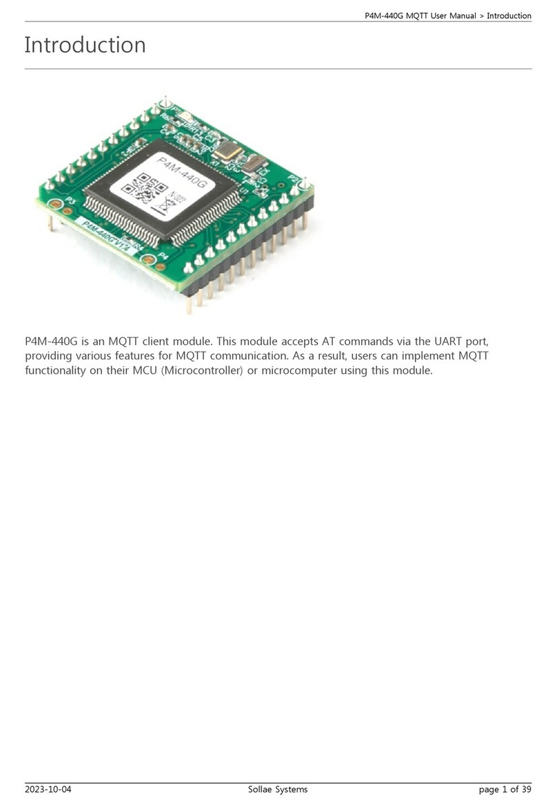
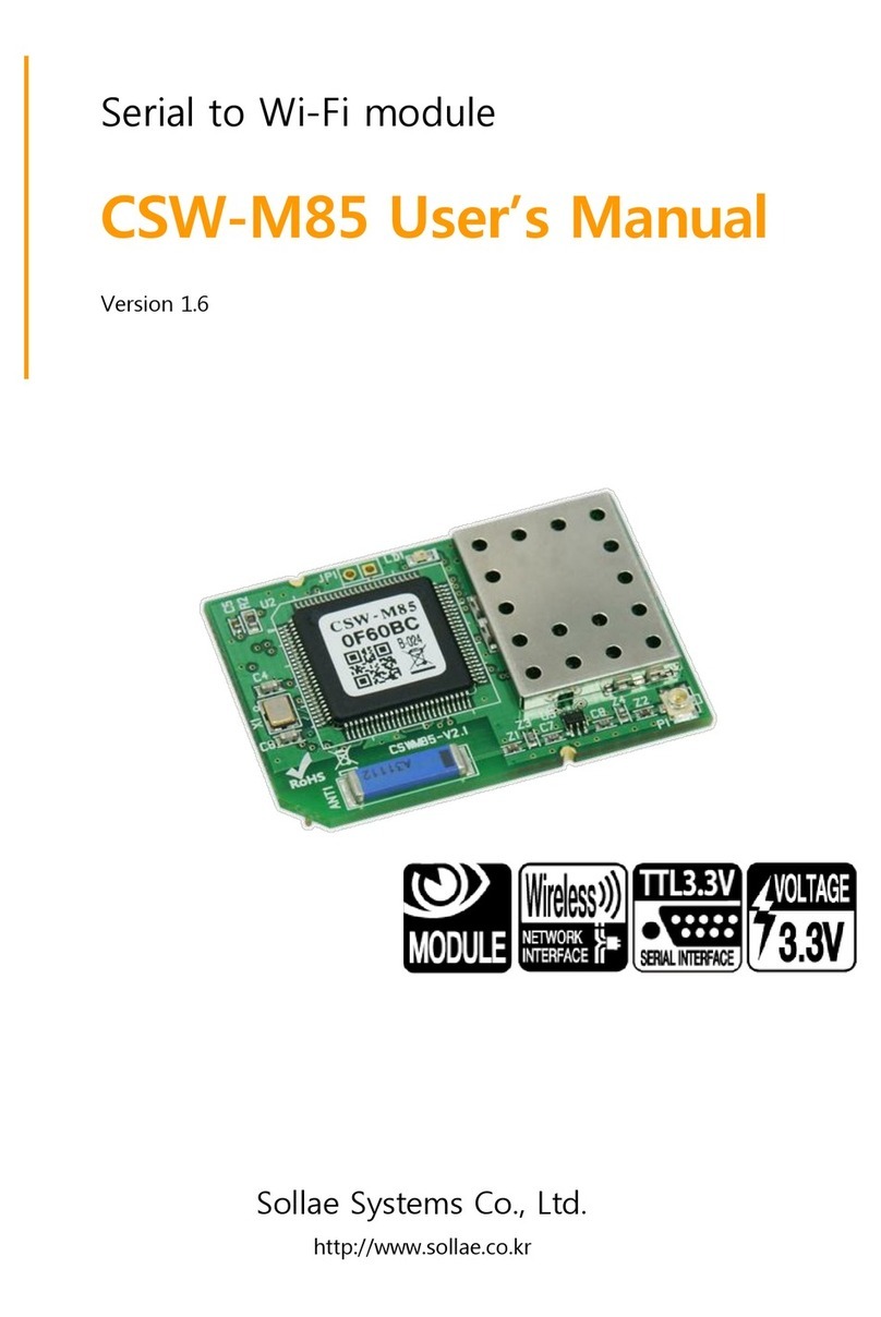
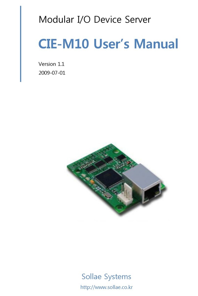
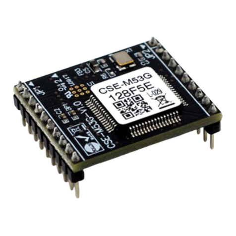
Sollae Systems EZL-90 User manual

EZL-90 Manual
Version 1.1
Sollae Systems Co., Ltd.

- 2 -
To all residents of the European Union
To all residents of the European UnionTo all residents of the European Union
To all residents of the European Union
Important environmental information about this product
Important environmental information about this productImportant environmental information about this product
Important environmental information about this product
This symbol on this unit or the package indicates that disposal of this unit
This symbol on this unit or the package indicates that disposal of this unit This symbol on this unit or the package indicates that disposal of this unit
This symbol on this unit or the package indicates that disposal of this unit
after its lifec
after its lifecafter its lifec
after its lifecycle could harm the environment. Do not dispose of the unit as
ycle could harm the environment. Do not dispose of the unit as ycle could harm the environment. Do not dispose of the unit as
ycle could harm the environment. Do not dispose of the unit as
unsorted municipal waste; it should be brought to a specialized company for recycling. It
unsorted municipal waste; it should be brought to a specialized company for recycling. It unsorted municipal waste; it should be brought to a specialized company for recycling. It
unsorted municipal waste; it should be brought to a specialized company for recycling. It
is your respons
is your responsis your respons
is your responsi
ii
ibility to return this unit to your local recycling service. Respect your
bility to return this unit to your local recycling service. Respect your bility to return this unit to your local recycling service. Respect your
bility to return this unit to your local recycling service. Respect your
local environm
local environmlocal environm
local environmental regulation. If in doubt, contact your local waste disposal authorities.
ental regulation. If in doubt, contact your local waste disposal authorities.ental regulation. If in doubt, contact your local waste disposal authorities.
ental regulation. If in doubt, contact your local waste disposal authorities.

- 3 -
-Table of Contents –
1. INTERFACE....................................................................................................................- 4 -
1.1. DC
I
NPUT
(JP5)...............................................................................................................-
4
-
1.2. D
SUB
9P
MALE
(P1)........................................................................................................-
5
-
1.3. DTR/DSR
LOOPBACK JUMPER
(JP6)...............................................................................-
5
-
1.4. A
LTERNATIVE
C
ONNECTOR
(JP8)....................................................................................-
5
-
1.5. LED
S
..............................................................................................................................-
6
-
1.6. LED
CLASSIFIED WITH OPERATION MODE
.......................................................................-
7
-
1.7. S
WITCHES
.......................................................................................................................-
8
-
1.7.1. Power Switch (JP1).......................................................................................................- 8 -
1.7.2. Reset Switch (S1)........................................................................................................... - 8 -
1.8. L
EVEL
C
ONVERTER
(U2).................................................................................................-
8
-
2. SCHEMATICS.................................................................................................................- 9 -
3. TECHNICALSUPPORT, WARRANTY,AND NOTES ON OPERATION.............- 10 -
3.1. T
ECHNICAL
S
UPPORT
....................................................................................................-
10
-
3.2. W
ARRANTY
..................................................................................................................-
10
-
3.2.1. Refund .........................................................................................................................- 10 -
3.2.2. Free Repair Services...................................................................................................- 10 -
3.2.3. Charged Repair Services.............................................................................................- 10 -
3.2.4. Notes on Operation ..................................................................................................... - 10 -
4. REVISION HISTORY..................................................................................................- 13 -

- 4 -
1. Interface
EZL-90 is a daughter board which supplies 3.3V power to EZL-80c and
an interface of RS232 to the EZL-80c.
1.1. DC Input (JP5)
DC5V is required to EZL-90 and the specification is below:
EZL-90 supplies 3.3V to the EZL-80c after regulating.

- 5 -
1.2. Dsub 9P male (P1)
number
name
description level Dir. Etc.
1 - - - - -
2 RXD
Receive Data RS232
Input Mandatory
3 TXD
Transmit Data RS232
Output
Mandatory
4 DTR
Data Terminal Ready
- - Optional
5 GND
Ground Ground
- Mandatory
6 DSR
Data Set Ready - - Optional
7 RTS
Request To Send RS232
Output
Optional
8 CTS
Clear To Send RS232
Input Optional
9 - - - - -
DTR and DSR can be loop backed with a DTR/DSR loopback jumper (JP6).
See the below section for more information.
1.3. DTR/DSR loopback jumper (JP6)
Some devices require DSR signal (DTR in terms of EZL-90). The devices
recognize the counterpart serial device with DSR. To get DSR signal from
the counterpart serial device, the counterpart serial devices have to
signal DTR.
EZL-90 has no DTR signal, but it has DTR/DSR loopback jumper. If user
set the jumper, EZL-90 returns its DSR signal from user device to DTR
so that user device recognizes the EZL-90.
1.4. Alternative Connector (JP8)

- 6 -
# Name Voltage
Level
Connection with
EZL-80c
Connection with
P1
1 3.3V 3.3V Power
3.3V
2 RXD RS232 RXD0 via line
driver RXD
3 TXD RS232 TXD0 via line
driver TXD
4 GND Ground GND GND
5 RTS RS232 RTS0 via line
driver RTS
6 CTS RS232 CTS0 via line
driver CTS
7 RST 3.3V RESET
8 LINK 3.3V LINK_LED
9 STS 3.3V STS_LED
10 LAN RXD 3.3V RXD_LED
11 LAN TXD 3.3V TXD_LED
12 P0 3.3V P0
13 P1 3.3V P1
14 RXD1 3.3V RXD1
15 TXD1 3.3V TXD1
16 SCK 3.3V SCK
1.5. LEDs
Name Color Description
PWR Red On: when power is on
RXD Yellow
Blink: when EZL-80c receives data from the
serial port
TXD Green
Blink: when EZL-80c transmits data to the serial
port
RTS Green
On: when RTS0 of EZL-80c is active (low)
CTS Yellow
On: when CTS0 line of EZL-80c is active (low)
STS Yellow
The status of EZL-80c
LINK Green
On: when EZL-80c is linked to the wireless LAN

- 7 -
LANRXD Yellow
Blink: when EZL-80c receives data from the
wireless LAN
LANTXD Green
Blink: when EZL-80c transmits data to the
wireless LAN
1.6. LED classified with operation mode
Mode Name
Status Description
Normal
mode
PWR
On Power is supplied
STS
Blinks in
every second
IP is allocated but TCP connection is
not established.
Blinks 4
times /sec
IP address is net assigned in DHCP
or PPPoE modes.
On TCP is connected
LINK
On EZL-80C is connected to the WLAN
RXD Blinks Receiving data from the serial
TXD
Blinks Transmitting data to the serial
LAN_
RXD Blinks Receiving data from the WLAN
LAN_
TXD
Blinks Transmitting data to the WLAN
RTS
On There are enough rooms to receive
data
Off There aren’t enough rooms to
receive data
CTS
On Counterparts’ buffer is enough to
receive data
Off Counterparts’ buffer isn’t enough to
receive data
ISP
/Serial
Config
mode
PWR
On
EZL-80C is in the ISP
/ Serial Config mode
STS Blinks rapidly
LINK
Off

- 8 -
1.7. Switches
1.7.1.Power Switch (JP1)
The Power Switch turns EZL-90 on.
1.7.2.Reset Switch (S1)
Reset Switch resets EZL-90. And it is connected to RST of JP8.
1.8. Level Converter (U2)
It converts TTL signal of EZL-80c to RS232 signal via versa.

- 9 -
2. Schematics
VCC_EXT
STS_LED
EX_DSRRXD0
TXD0
H8
HOLE-2
11
R2
AR9-200
1
2
3
4
5
6
7
8
9
1
2
3
4
5
6
7
8
9
VCC_33
RESET
H5
HOLE-2
11
D9
LED 12
JP7
HEADER 16X2
1 2
3 4
5 6
7 8
9 10
11 12
13 14
15 16
17 18
19 20
21 22
23 24
25 26
27 28
29 30
31 32
RESET
D6
LED 12
VCC_33
TXD0
H7
HOLE-2
11
RXD0
EX_CTS
RXD1
P0
SCK
EX_DTR
H6
HOLE-2
11
RXD0
D10
LED 12
TXD0
P1
+
C5
1UF
1 2
VCC_33
RXD_LED
D3
LED 12
STS_LED
RXD1
JP2
HEADER 6
1
2
3
4
5
6
TXD1
RESET
VCC_33
+
C1
47UF
TXD_LED
LINK_LED
CTS0
EX_TXD
SCK
VCC_33
SCK
D1
1N4001
12
JP1
SW_SLIDE
1
2
3L
C
R
TXD0
JP8
HEADER 16
1
2
3
4
5
6
7
8
9
10
11
12
13
14
15
16
RESET
S1
SW PUSHBUTTON
JP6
JUMPER
1 2
D7
LED 12
CTS0
RTS0
P1
CONNECTOR DB9
5
9
4
8
3
7
2
6
1
10
11
R1 200
P0
VCC_33
H2
HOLE-2
11
STS_LED
H3
HOLE-2
11
U2
MAX232
5
9
46
3
12
1
710
2
11
15
14
16
8
13
C2-
R2OUT
C2+ V-
C1-
R1OUT
C1+
T2OUTT2IN
V+
T1IN
GND
T1OUT
VCC
R2IN
R1IN EX_RXD
P0
TXD_LED
TXD_LED
EX_RTSRTS0
EX_CTS
+
C4
1UF
1 2
EX_DSR
D5
LED 12
P1
H4
HOLE-2
11
JP5
POWER JACK
1
2
3
5V
GND
GND
VCC_5
+
C7
1UF
1 2
RESET
SCK
CTS0
RXD_LED
EX_TXD
LINK_LED
D2
LED 12
RXD_LEDRXD_LED
TXD_LED
VCC_33
LINK_LED
TXD1
VCC_5
VCC_33
+
C3
10UF
+
C6
1UF
12
D8
LED 12
VCC_33
STS_LED LINK_LED
+
C2
10UF
RXD0
EX_RTS
RXD0
CTS0
D4
LED 12
U1 AMS1086
23
1
4
VOUTVIN
G
TAB
VCC_33
TXD1
RTS0
RTS0
P1
H1
HOLE-2
11
RXD1
EX_DTR
EX_RXD
TXD0
MAIN 1.0
EZL-90
A4
1 1, 3 30, 2004
Title
Size Document Number Rev
Date: Sheet of

- 10 -
3.
Technical Support, Warranty, and Notes on
Operation
3.1.
Technical Support
If you have any question regarding operation of the product, visit
Customer Support FAQ corner and the message board on Sollae Systems’
web site or send us an email at the following address:
Website Address for Customer Support:
http://www.eztcp.com/en/Support/support.php
3.2.
Warranty
3.2.1.
Refund
Upon the customer’s request to refund the product within two weeks
after purchase, Sollae Systems will refund the product.
3.2.2.
Free Repair Services
For product failures occurring within one year after purchase, Sollae
Systems provides free repair services or exchange the
product. However, if the product failure is due to user’s fault, repair
service fees will be charged or the product will be replaced at user’s
expense.
3.2.3.
Charged Repair Services
For product failures occurring after the warranty period (one year) or
resulting from user’s fault, repair service fees will be charged and the
product will be replaced at user’s expense.
3.2.4.
Notes on Operation
Sollae Systems is not responsible for product failures occurring
due to user’s alternation of the product.
Specifications of the product are subject to change without prior

- 11 -
notice for performance improvement.
Sollae Systems does not guarantee successful operation of the
product if the product was used under conditions deviating from the
product specifications.
Reverse engineering of firmware and applications provided by
Sollae Systems is prohibited.
Use of firmware and applications provided by Sollae Systems for
purposes other than those for which they were designed is
prohibited.
Do not use the product in an extremely cold or hot place or in a
place where vibration is severe.
Do not use the product in an environment in which humidity is
high or a lot of oil exists.
Do not use the product where there is caustic or combustible gas.
Sollae Systems does not guarantee normal operation of the
product under the conditions a lot of noise exists.
Do not use the product for a purpose that requires exceptional
quality and reliability relating to user’s injuries or accidents –
aerospace, aviation, health care, nuclear power, transportation, and
safety purposes.

- 12 -
Sollae Systems is not responsible for any accident or damage
occurring while using the product.

- 13 -
4. Revision History
Date Version
Comment
Aug. 08. 2006
1.0 The first Release
Mar.24.2009
1.1 Add 1.6 LED classified with operation mode
Correct some expressions
Modify 3.1 Technical Support
Table of contents
Other Sollae Systems Control Unit manuals
Popular Control Unit manuals by other brands

System Sensor
System Sensor M500S Installation and maintenance instructions

WAGO
WAGO WAGO-TO-PASS 761 manual

Kidde
Kidde GSA-UM Installation sheet

Pfeiffer Vacuum
Pfeiffer Vacuum DCU 002 operating instructions

Lubeworks
Lubeworks 1813351 instruction manual

Hitachi
Hitachi CSC-5S Installation and operation manual