Sollae Systems EZL-200 User manual

EZL-200 User's Manual
Revision B
Sollae Systems

Table of Contents
1. Overview ··················································································································· 1
1.1. Components ······································································································ 1
1.2. Specifications ···································································································· 1
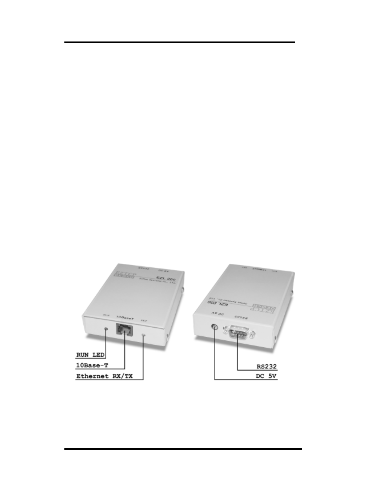
1.3. EZL-200 Layout ································································································ 1
1.4. Installation ·········································································································· 2
1.5. Feature Overview ····························································································· 2
2. Getting Started with ezTCP ················································································· 3
2.1. ezTCP Configuration ······················································································· 3
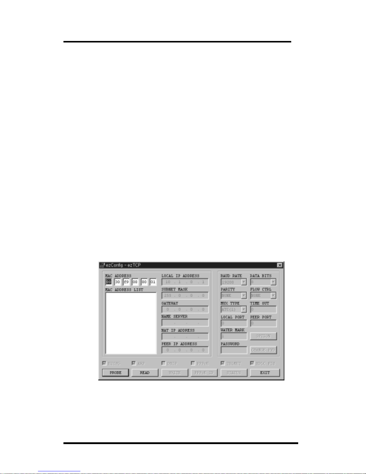
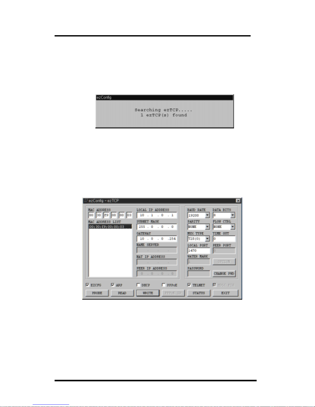
2.1.1. ezConfig ······································································································· 3
2.1.2. Basic Function Setup ··············································································· 5
2.2. Communication Test ······················································································· 7
3. Advanced Function of ezTCP ··········································································· 10
3.1. Serial Port Interface ······················································································ 10
3.1.1. T2S (TCP to Serial) ··············································································· 10
3.1.2. ATC (AT Command) ·············································································· 10
3.1.3. COD (Connect On Demand) ······························································· 11
3.1.4. TCP Connection Time Out (TIME OUT) ·········································· 11
3.2. AT Command Interface ················································································ 13
3.2.1. Basic AT Command ··············································································· 13
3.2.2. Extended AT Command ········································································ 13
3.2.3. AT COMMAND Escape Sequence ····················································· 14
3.2.4. Examples of ATC Application ······························································ 15
3.3. Environment Setup ························································································ 17
3.3.1. Environment Setup in ATC mode ······················································ 17
3.3.2. IP Address Setup using ARP ····························································· 18
3.3.3. IP Address-related Item Setup through DHCP Server ····················· 19
3.3.4. IP Address-related Item under Environment with ADSL ·············· 19
3.3.5. Environment Setup using Telnet or Console ·································· 19
3.4. ezTCP Environment Setup Item ································································ 22
3.4.1. Network related Setup Item ································································· 22

3.4.2. Serial Port Setup Item ·········································································· 22
3.4.3. Serial Port Interface related Item ······················································· 23
3.4.4. Miscellaneous ··························································································· 23
3.4.5. ezTCP Operation according to Console Jumper ···························· 23
3.4.6. STATUS LED State Variation ····························································· 24

EZL-200 User's Manual
1
1. Overview
1.1. Components
- EZL-200
- RS232 Cable
- DC 5V SMPS Power Adaptor
1.2. Specifications
- Processor: 16 bit
- Memory: ROM 128K / RAM 128K
- Interface: 10Base-T, 9 Pin D-Sub Male
- Protocols: TCP/UDP/IP/ICMP, Ethernet, ARP, PPPoE,
DHCP, TELNET server/client
- Power: DC 5V ± 10%
1.3. EZL-200 Layout

EZL-200 User's Manual
2
1.4. Installation
- Make sure that RUN LED is blinking regularly after the power is
turned on. If LED is not turned on, make sure that the power
adaptor is connected firmly.
- After checking LED, connect RS232 cable and 10Base-T cable to
each port of the main body separately, and then EZL-200 is now
available.
1.5. Feature Overview
EZL-200 (hereafter ezTCP) is a serial port to TCP/IP converter, in
which one serial port and one Ethernet port (10Base-T) are installed.
The serial port should be connected to a serial port of the control unit
(hereafter DTE) and the Ethernet port should be connected to a
switching hub (or dummy) compatible with the 10Base-T standard. The
following figure outlined a serial to Ethernet conversion system
configured with ezTCP:
If a host computer (hereafter a host) is connected to the TCP port of
ezTCP over an Ethernet network, the serial port of the DTE is
connected virtually to the TCP port of the host. Then, ezTCP will
function as an intermediate device between the serial port and the
TCP port.
Controller
Terminal
Remote Dev

EZL-200 User's Manual
3
2. Getting Started with ezTCP
2.1. ezTCP Configuration
This section describes how to configure and test T2S mode, which is
the most convenient mode among the serial port interfaces of ezTCP.
For more information about the other modes, see the following
sections.
2.1.1. ezConfig
The basic environment information of EZL-200 can be configured
through console, telnet, DHCP, ARP, and ezConfig. This section takes
an example of using ezConfig, which is an Integrated Management
Application for Windows. For the other configuration modes, see the
following sections. ezConfig can run on Microsoft Windows platform but
may not operate on some of the existing operating systems. The
screen below shows the initial screen of ezConfig:

EZL-200 User's Manual
4
Each button on ezConfig functions as follows:
This button is used to search for all of the network-attached
ezTCPs. The search results will be displayed on the MAC ADDRESS
LIST box and you can select an item using a mouse or cursor as
required. The value displayed on the box indicates the MAC
ADDRESS of each ezTCP. The selected setup value of ezTCP will
be displayed on the right side.
You can see only the ezTCP configuration details if you
press this button after entering the 6-digit hexadecimal number
printed on the ezTCP main body in the MAC ADDRESS box. It is
useful when there are too many ezTCPs attached to the network to
search for one from the LIST box.
This button is used to save the changed value in ezTCP
after modifying the configuration. Make sure not to press this button
during operating ezTCP since ezTCP will automatically be reset right
after its environment setup value is saved. Otherwise, it may cause
malfunction.
This button is used to close ezConfig. You can also close it
by pressing ESC key on the keyboard.
ezTCP provides User Authentication function to prevent an
unwanted person from modifying the configuration. The authentication
process is performed through the password string verification. When
entering or changing the password strings, you can use this button.
Changing the ezTCP configuration details if a password has been
entered requires the proper password to be entered in the
PASSWORD field.
This button is used to read a dynamic variable value during
operating ezTCP. Pressing this button will display a new window,
where the time-lapse after the power is on, the current IP address,
and the data throughput of the serial port are indicated.
Double-clicking each item on the MAC ADDRESS LIST will carry out
the same function.

EZL-200 User's Manual
5
ezConfig can be used to change the IP address related items, the
serial port setup value, the serial port operation mode, and how to
setup ezTCP. This section describes these functions briefly. For more
information, see the following sections. The items you should setup
when using T2S mode of ezTCP are listed as follows:
LOCAL IP ADDRESS ezTCP IP address
SUBNET MASK subnet mask
GATEWAY network gateway
BAUD RATE UART port baud rate
DATA BITS UART data bits
PARITY UART parity
FLOW CTRL hardware flow control
MUX TYPE ezTCP serial interface type
TIMEOUT connection time out
LOCAL PORT listening TCP port number
2.1.2. Basic Function Setup
The following example shows how to read and change ezTCP's
basic functions. Try changing ezTCP setup value according to the
following sequence:
- When the ezTCP power is turned on and the LAN cable is
connected correctly, pressing [PROBE] or [READ] button will display
the following window:

EZL-200 User's Manual
6
- If a network-attached ezTCP is detected, the following message will
be displayed. If a message pops up indicating that there is no
response from ezTCP, check that the power is turned on and the
cable is connected correctly, then try pressing [PROBE] or [READ]
button.
- If more than one ezTCP is detected, ezTCP's MAC ADDRESS will
be displayed in the [MAC ADDRESS LIST] box on ezConfig. Check
if the MAC ADDRESS displayed in the [MAC ADDRESS LIST]
window corresponds to that printed on ezTCP main body. The
following screen shows this process:
- Select T2S (0) in the [MUX TYPE] field on ezConfig. Setup [LOCAL IP
ADDRESS], [LOCAL PORT], and the serial port settings according to a test
environment as required. When the setup is completed, pressing [WRITE]
will save the changed values in ezTCP. If an error message pops up
during storing the configuration, check that ezTCP is connected correctly,
and then try again.

EZL-200 User's Manual
7
- In Windows' MS-DOS prompt window, check the IP address is set
correctly by giving the PING command. If the ezTCP IP address is
set correctly, the PING results will be displayed as follows. If a
message, "Request timed out", is displayed, check that IP address
setup value again.
C:\>ping a.b.c.d
Pinging a.b.c.d with 32 bytes of data:
Reply from a.b.c.d: bytes=32 time=1ms TTL=64
2.2. Communication Test
You can conduct a simple test using Hyper Terminal or telnet
terminal for Windows if the IP-related items of ezTCP are set correctly
through ezConfig. A communication test will be conducted as follows:
- Connect the serial cable to the serial ports of both ezTCP and PC
respectively.
- Run Hyper Terminal, change the serial port baud rate, data bit, parity
bit and flow control, and then save the changed values. Each setup
value must correspond to those configured by ezConfig.
- In Windows' MS-DOS prompt window, run telnet terminal according
to the following process. Note that a.b.c.d is the ezTCP IP address
and xxxx is the value of ezTCP's [LOCAL PORT]:
C:\>telnet a.b.c.d xxxx

EZL-200 User's Manual
8
- If telnet terminal is successfully connected, RUN LED of ezTCP will
stop blinking and shift to a constant lightened state. If RUN LED is
blinking regularly after running telnet terminal, check ezTCP setup
value again.
- If the telnet terminal connection is successfully established, Hyper
Terminal and telnet terminal will be connected to each other through
ezTCP as shown in the following picture:
- When the two ends are connected to each other, a character input
from telnet terminal will be output to Hyper Terminal, and vice versa.
- When "abcd" is input on telnet terminal, the output result is shown
as follows:
- When "1234" is input from Hyper Terminal, the output result is

EZL-200 User's Manual
9
shown on telnet terminal as follows:
- If the text appears garbled, check if items related to the serial port
of ezTCP correspond to the serial port setup value of Hyper
Terminal.
- If nothing is input on the keyboard for specified period of time when
the [TIME OUT] value of ezConfig is set bigger than 0, telnet
terminal will terminate the connection while displaying a connection
termination message.

EZL-200 User's Manual
10
3. Advanced Function of ezTCP
3.1. Serial Port Interface
ezTCP supports three types of the serial communication interface
mode: T2S, ATC, and COD. In T2S and COD modes, you can use
ezTCP by simply connecting the serial port without modifying existing
equipments' software. While in ATC mode, the existing equipments'
software needs modifying. For ATC mode, the AT emulation function is
supported and it allows you to use ezTCP for a standard modem.
Those who have experienced with modem operation will take
advantage of the full ezTCP functions without effort. EZL-200 supports
the three interface types on-board and you can select those functions
through telnet, AT emulation, console, or ezConfig. The typical
functions of each mode are listed below. The note at the end of each
paragraph describes the items you should change through ezConfig
when using the relevant mode.
3.1.1. T2S (TCP to Serial)
In this mode, ezTCP always wait for a connection request from an
external device without voluntarily connecting itself to an external
server or PC. In case an external host is connected to the specified
port of ezTCP, ezTCP will connect the serial port to the TCP port.
That is, it transmits data from the serial port to the TCP port and data
from the TCP port to the serial port. This mode allows you to use
ezTCP without modifying the existing equipment's software while using
COD mode. In T2S mode, care should be taken that all data from the
DTE to the serial port will be ignored until a connection from a certain
external PC to ezTCP is established.
* setup fields: [TIME OUT], [LOCAL PORT]
3.1.2. ATC (AT Command)
You can use ezTCP for a standard modem. The extended
commands supported by ezTCP allow you to designate the IP address
and the port number of a host on the Internet and connect it through

EZL-200 User's Manual
11
ATD (T) command. After designating the connection standby port,
using ATA command will also connect a host to ezTCP. For more
information, see the following sections.
* setup fields: [TIME OUT]
3.1.3. COD (Connect On Demand)
COD mode allows ezTCP to voluntarily connect with the TCP port on
an external PC or a server. When a DTE transmits data to the serial
port, ezTCP will attempt connecting with a certain TCP port on the
specified computer that already has IP address. If the connection is
successful, this mode will transmit data already received from the serial
port to the TCP port, and then exchange data between the TCP port
and the serial port like the T2S mode. In COD mode, a TCP
connection will begin when the size of data received from the serial
port exceeds the pre-specified size (water mark), and the size is
changeable (factory-set value is 1 byte). If the setup value is 0, a
connection will begin right after the power is turned on.
* setup fields: [TIMEOUT], [WATER MARK], [PEER PORT], [PEER IP
ADDRESS]
3.1.4. TCP Connection Time Out (TIME OUT)
ezTCP will terminate the connection if there is no data exchange for
a specified period of time. The time period can be selected from 1 to
600 seconds, and the Time Out function is cleared if the time period
is set to 0 second. If the Time Out is set to 10 seconds, the
connection will be terminated after ten seconds when transmitting the
last data. If the Time Out function is cleared, some problem may occur
because the TCP connection status of ezTCP will remain unterminated
when a host connected to ezTCP is shut down abnormally. If the Time
Out is set to 0, the Keep-alive function on the TCP will be activated
while the Time Out function is cleared. The Keep-alive transmits the

EZL-200 User's Manual
12
keep-alive packets and waits for their responses if there is no data
exchange for a specified period of time. If no responses to the
keep-alive packets are received consecutively for five times, it will
forcibly terminate the current TCP connection. You do not need to pay
attention to this operation since it is the internal TCP module function.
The keep-alive function is optional for the TCP/IP protocol specification.
On some operating systems, this function may not be available. If you
want to terminate the connection from ezTCP in COD mode, it is
recommended to use the Time Out function.

EZL-200 User's Manual
13
3.2. AT Command Interface
In ATC mode, using the standard AT command and the ten
extended AT commands enables you to access the Internet. If the
connection is successful CONNECT message is displayed and if the
connection is failed or terminated NO CARRIER message is displayed,
which is similar to a standard modem. The modem commands
supported by ezTCP are listed below:
3.2.1. Basic AT Command
Command Function Note
Apassive connection Host >> ezTCP connection
Dactive connection ezTCP >> Host connection
Eecho E0-disable / E1-enable
Hoff-hook hang-up call
IInquiry ezTCP information output
OOnline online command state >> online
Venable result code V0-numeric, V1-string
Zreset reset AT command module
3.2.2. Extended AT Command
ezTCP provides the unique extended command for the control of the
Internet-related setup values, which are not supported by a standard
modem. The extended AT commands start with 'AT+P' and are
followed by the equal sign, '=', for setting up values. The question
mark, '?', should be added to the end of the command when
outputting the setup value. For example, enter the command when
changing or checking ezTCP's IP address as follows:
AT+PLIP=a.b.c.d >>
<< OK
AT+PLIP? >>
<< a.b.c.d
The extended commands available on ATC mode are listed below:

EZL-200 User's Manual
14
Command Function Note
+PLIP local IP address
+PSM subnet mask
+PGIP default router
+PLP listening TCP port
+PTO timeout
+PRIP remote machine IP address
+PRP remote machine TCP port
+PWP write configuration write setting to EEPROM
* Setup Value ON/OFF Command: PRC (EZCFG), PARP (ARP), PDC
(DHCP), PPE (PPPoE), and PRL (TELNET)
* The ON/OFF commands are set to ON (1) or OFF (0).
3.2.3. AT COMMAND Escape Sequence
When forcibly terminating the TCP connection of ezTCP, you should
shift the online state to the online command state through '+++'
escape sequence. Under the online command state, entering ATH will
terminate the TCP connection and entering ATO will restore it to the
online state. The guard times are required before and after the '+++'
character transmission as follows:
Until inputting 1st '+' after the last transmit More than 500ms
‘+’ input interval 0~500ms
delayed time after inputting the last ‘+’ More than 500ms
* Note: The figures above require the guard time be set to 500
milliseconds.

EZL-200 User's Manual
15
3.2.4. Examples of ATC Application
- Telnet server connection (client mode):
AT+PRIP=aa.bb.cc.dd : Telnet Server IP Address >>
AT+PRP=23 : Telnet Port Number >>
ATDT >>
<< CONNECT
<< Data transmission/reception >>
* In case the telnet server terminates the connection:
<< NO CARRIER
* In case the DTE terminates the connection:
<guard time> '+++' <guard time> >>
<< OK
ATH : Connection Termination >>
<< OK
- TCP port no. 6000 connection:
AT+PRIP=aa.bb.cc.dd : Server IP Address >>
AT+PRP=6000 : Port Number >>
ATDT >>
<< CONNECT
<< Data Transmission/Reception >>
- Server Mode:
AT+PLP=6000 : listening TCP port >>
<< OK

EZL-200 User's Manual
16
ATA >>
wait until remote host connects to ezTCP
<< CONNECT : connection notifier
<< Data Transmission/Reception >>
<< NO CARRIER : connection terminated
- Examples of using Multiple Commands:
Like a standard modem, ezTCP supports simultaneous multiple
commands input. Forbidding the echo command, outputting the return
value as the number instead of the string, and connecting to the TCP
port no. 6000 are exemplified as follows:
ATE : Echo forbidden >>
<< OK
ATV+PRIP=aa.bb.cc.dd+PRP=6000DT : actually. >>
<< 1
<< Data Transmission/Reception >>

EZL-200 User's Manual
17
3.3. Environment Setup
Environment variables such as the IP address, the serial port rate,
the connection port number, and the serial communication mode can
be changed by using AT command, the internal shell applications of
ezTCP, and ezConfig.
3.3.1. Environment Setup in ATC mode
After changing the environment setup value, you must use the +PWP
command. +PWP is used to store the changed value in the actual
EEPROM. If the ezTCP power is turned on or EEPROM configuration
is changed by +PWP command, NO CARRIER message is displayed.
The examples listed below are for setting each item:
AT+PLIP=aa.bb.cc.dd : ezTCP's IP Address >>
<< OK
AT+PGIP=bb.cc.dd.ee : Gateway IP Address >>
<< OK
AT+PSM=255.255.255.0 : Subnet Mask >>
<< OK
AT+PLP=1470 : ezTCP's Listening TCP Port >>
<< OK
AT+PTO=10 : Reception Time Out >>
<< OK
AT+PWP : Storing the Setup Value >>
<< OK
<< NO CARRIER
Table of contents
Other Sollae Systems Server manuals

Sollae Systems
Sollae Systems IDIS-200 User manual

Sollae Systems
Sollae Systems CSE-H20 User manual

Sollae Systems
Sollae Systems CSE-H21 User manual

Sollae Systems
Sollae Systems CSW-H80 User manual

Sollae Systems
Sollae Systems CSE-M32 User manual

Sollae Systems
Sollae Systems EZL-200L User manual

Sollae Systems
Sollae Systems CSE-H20 User manual

Sollae Systems
Sollae Systems CSE-H25 User manual

Sollae Systems
Sollae Systems EZL-200F User manual

Sollae Systems
Sollae Systems PBH-101 User manual