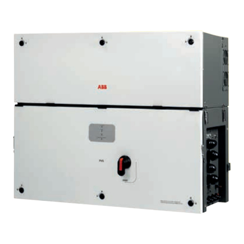
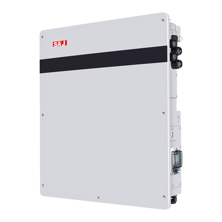
Soltaro AIO2-INS Series User manual

Operating Manual
AIO2-INS Series

1
Version: DM-AIO2-INS-EN 1.1

2
1About This Manual ................................................................................. 1
1.1 Products Covered by This Manual ........................................... 1
1.2 Target Group............................................................................... 1
1.3 Symbols Used .............................................................................. 1
1.4 Storage of the Manual............................................................... 1
2Safety....................................................................................................... 2
2.1 Intended Use............................................................................... 2
2.2 Important Safety Instructions..................................................... 2
2.3 Storage and Transportation ...................................................... 3
3Scope of Delivery................................................................................... 4
4Product Description ............................................................................... 6
4.1 View of the Inverter .................................................................... 6
4.2 Topology of the Inverter ............................................................ 8
4.3 System Diagram.......................................................................... 8
4.4 Operating Mode Introduction .................................................. 9
5Mounting............................................................................................... 12
5.1 Requirements for Mounting..................................................... 12
5.2 Mounting the Inverter (with AIO2-BTLV-5KWH battery)........ 14
5.3 Mounting the Inverter (with AIO2-BTLV-10KWH battery)...... 18
6Electrical Connection.......................................................................... 23
6.1 Wiring Diagram ......................................................................... 23
6.2 Wiring Diagram ......................................................................... 24
6.3 Overview of the Connection Area ........................................ 25
6.4 PV Connection ......................................................................... 25
6.5 Grid Connection....................................................................... 27
6.6 EPS Connection ........................................................................ 28
6.7 Battery Connection.................................................................. 30
6.8 Smart Meter Connection......................................................... 32
6.9 WiFi Stick Connection ............................................................... 33
6.10 DRM Connection ...................................................................... 34
7Operating of the Inverter .................................................................... 35
7.1 Graphical Display..................................................................... 35
7.2 Commission ............................................................................... 36
7.3 Decommission........................................................................... 37
7.4 Settings on the Soltaro APP ..................................................... 38
8Troubleshooting.................................................................................... 45
9Technical Data..................................................................................... 48
9.1 Specification of inverter........................................................... 48
9.2 Specification of battery........................................................... 50
9.3 Certificates and Grid Regulations .......................................... 51
Contacts:...................................................................................................... 52

1
1About This Manual
1.1 Products Covered by This Manual
AIO2-INS Series Low Voltage Solar Hybrid Inverter:
AIO2-INS-3000, AIO2-INS-3680, AIO2-INS-4600, AIO2-INS-5000.
1.2 Target Group
This document is intended for qualified electrician. Any electrical
installation and maintenance on this inverter must be performed by
qualified electricians in compliance with standards, wiring rules or
requirements of local grid authorities or bodies.
1.3 Symbols Used
The following types of safety precautions and general information
symbols are used in this manual. These important instructions must be
followed during installation, operation and maintenance of the
inverter.
Indicates a hazard with a high level of
risk that will result in death or serious
injury.
Indicates a hazard with a medium level
of risk that can result in death or serious
injury.
Indicates a hazard with a low level of
risk that can result in minor or moderate
injury.
Indicates a situation which, if not
avoided, can results in property
damage.
1.4 Storage of the Manual
The manual should be stored with other documents belonging to
the inverter and must be available to people authorized to work

2
on the installation.
This manual will be updated if necessary. Please check www.soltaro.com for more
information.
2Safety
2.1 Intended Use
The AIO2-INS Series are single phase solar hybrid inverters suitable for
both on-grid and off-grid operation. With Lithium batteries, PV panels
and a smart meter, the hybrid inverter is the central device to make
a solar storage system for increased self-consumption.
The AIO2-INS Series must only be connected with a Soltaro lithium
battery.
To prevent personal injury and property damage and to ensure
long-term operation of the product, please read and follow all the
instructions and cautions on the inverter and this user manual during
installation, operation or maintenance at all times.
2.2 Important Safety Instructions
Danger to life from electric shock.
•Before performing any work on the inverter, disconnect all
DC and AC power from inverter and wait for at least 5
minutes.
•Do not touch DC conductors or any non-isolated cable
ends.
•If an error occurs, contact your local distributor or
qualified electricians.
•Make sure the inverter is not touchable from children.
Risk of burns from hot surfaces.
•The surface of the inverter might exceed 60℃, touching
the surface may result in burns.

3
•Do not touch hot surfaces before it cools down.
•Only authorized service personnel are allowed to install
the inverter or perform servicing and maintenance
•All powers, both AC and DC, should be disconnected
from inverter before attempting any maintenance or
cleaning or working on any circuits connected to inverter.
•The Inverter has a transformerless design on PV side. Either
positive or negative terminals of PV panels should not be
grounded.
•The frames of PV panels should be grounded for safety
reasons.
•Do not open inverter cover or change any components
without authorization, otherwise the warranty
commitment for the inverter will be invalid.
•Appropriate methods must be adopted to protect
inverter from electrostatic discharge, any damage
caused by ESD is not warranted by the manufacturer.
2.3 Storage and Transportation
Store the inverter in a dry environment where ambient temperature
is always between -20 °C - +60 °C. Take care of the inverter during
the storage and transportation.
The package shall not be tilted or inverted during transportation,
handling and storage.
When the inverter or other related components need to be disposed,
make sure it is carried out according to local waste handling
regulations. Please be sure to deliver waste inverters and packing
materials to appropriate recycling center’s where possible.

4
3Scope of Delivery
A
B
C
D
E
F
G
H
1 2
3 4
5 6
7 8
I
J
K
L
M
N
Item
QTY
Designation
A
1
Inverter
B
1
Wall Mounting Bracket

5
C
2
Battery power cable(red cable is positive
connection, black cable is negative
connection)
D
1
RJ45 Connectors
E
1
EPS Connector (Amphenol or Wieland)
F
1
Grid Connector (Phoenix or Wieland)
G
2
PV Connectors (Amphenol HC4 or
Multi-Contact MC4) (2PV+,2PV-)
H
1
WiFi Stick (optional)
I
1
CT and Smart Meter
J
3
Terminal Resistor (1kOhm)
K
1
Smart Meter Communication Connector
L
8
Screws for Fixing Mounting Bracket
M
1
BMS Cable
N
1
Manual

6
4Product Description
Thank you for choosing the SOLTARO AIO2 ESS product.
Features of the inverter are ahead of the field and should be
understood prior to install.
4.1 View of the Inverter
Figure 1. View of the AIO2-INS Series Hybrid Inverter
Position
Designation
A
Graphical Display
B
LED light. When inverter is running normally, the
light is green. When error occurs, the light turns
red.
B
A

7
Symbols on the Type Label
Symbol
Explanation
CE Mark
Caution, Risk of Danger
Caution, Risk of Electric Shock
Caution, Hot Surface.
Refer to the Operating Manual
5min
Danger, Risk of Electric Shock due to Stored
Energy. Cut off all power and wait at least 5
minutes before any work is carried out on the
inverter.
G98 or G99 Mark for UK.
RCM Mark for Australia and New Zealand.
WEEE Mark. This inverter should not be
disposed as ordinary waste.

8
4.2 Topology of the Inverter
Figure 2. AIO2-INS Series Hybrid Inverter topology
4.3 System Diagram
kWh
PVArray Hyper-S Router
Internet
Loads Smart
Meter
Billing
Meter
Mobile APP Grid
DC
AC
Communication

9
4.4 Operating Mode Introduction
4.4.1 On Grid Self-Use Operating Mode
The on grid self-use operating mode is recommended for when the
system is installed in an area with a stable grid. The purpose is to
increase self-consumption of clean PV energy. When Inverter is set
to work in this mode:
i.
During daytime and there is sufficient PV Power,
•
The PV energy is used to supply local loads as first priority and
then charge the battery, excess energy will be fed into
grid*1*2.
•
When battery is fully charged, PV energy is supplied to the
local loads and fed into grid*1*2.
ii.
During nighttime or there is not sufficient PV Power,
•
Battery is discharged to supply local loads, if extra power is
required, it will be imported from grid.
•
When the battery SOC is below the DischargeEndSOC@Grid
value or fully discharged, the inverter will stop working and
local loads will be supplied from the grid.
•
Thanks to the on-grid operation, the switch from battery
power, PV power and grid power is automatic and seamless.
iii.
When grid fails,
•
When grid fails, the inverter will automatically disconnect
from grid and output power to the EPS port.
•
When battery is discharged to the DischargeEndSOC@EPS
value, the inverter will stop working and wait for the grid to
recover or until there is sufficient power from PV panels to
charge the battery.
•
If grid failure can be a common occurrence in your area, you
can adjust the DischargeEndSOC@Grid higher to ensure
there is battery power available.
iv.
You can also:

10
•
Set a schedule for the inverter to charge the battery using
cheap off-peak grid power.
•
Specify the daily working periods of self-use for inverter.
*1: The inverter can be set not to feed power into the grid. But a
small amount of energy will still inevitably be fed into grid due to
unpredictable PV energy change and load fluctuations.
*2: Firmware update may be required to support this function.
For on-grid self-use operating mode, one can set the discharge end
SOC@Grid as low as the battery allows (10% or 20% for example).
Please refer to your local battery technician for minimum discharging
end SOC.
4.4.2 Off Grid / Back-up Operating Mode*3
For systems installed in area with a weak grid or even without grid,
the inverter should be working in off grid / back-up operating mode:
i.
When grid or diesel generator is available,
•
When the battery is below the DischargeEndSOC@Grid value,
it will be charged firstly from PV and secondly from grid at the
max allowable current.
•
When the battery is above the DischargeEndSOC@Grid value,
it will be charged by excess PV energy and will discharge if
the PV power is not enough to support the loads.
ii.
When grid or diesel generator is not available,
•
When there is enough energy stored in the battery, the EPS
port will export power to support local loads firstly from PV. If
there’s excess PV energy, it will be used to charge the battery.
Otherwise battery will be discharged to feed the load.
•
When the battery SOC is below the DischargeEnd SOC@EPS
value, the inverter will disconnect power to the EPS port. All
energy from PV will be used to charge the battery until the

11
SOC reaches the EPS restart value.
iii.
When working in this mode:
•
The max power*3 from the EPS port is limited by inverter type,
battery type and battery SOC.
•
A larger battery is always recommended for off grid / backup
configuration. You should never discharge the battery too
deeply to avoid it “Running Flat”.
•
When there is an overload or short circuit fault, the inverter will
stop working and an alarm will sound. It will try to restart
several times before shutting down completely. Turn off or
unplug load to remove the short circuit fault or overload as
soon as possible.
*2: Firmware update may be required to support this mode.
*3: Please be noted that refrigerators, air conditioners, water pumps
and etc., demand a large start up currents and may trip EPS
overload protection. Be sure not to connect too many of this kind of
load to avoid frequent system shutdown and restart.
For off-grid / back-up operating mode, one should set a
higher DischargeEndSOC@Grid value (above 50% for
example). So that there will be some energy in battery when a
grid failure occurs.

12
5Mounting
5.1 Requirements for Mounting
Check to make sure the installation site does not fall into any of the
following conditions: If it does, then a risk assessment will be required.
No direct sunlight
No rain exposure
No snow lay up
Direct sunlight
Rain exposure
Snow lay up
Additional Notes:
•Unsafe due to assessment of occupational health safety
Position
Min.size
Left
600
Right
600
Top
600
Bottom
600
Front
300
Clearance requirements

13
risks.
•The ambient temperature is outside the range of tolerable
ambient temperature (-20°C to +60°C, -4°F to+140°F).
•Higher than the altitude of 2,000m above sea level. Above
2000m the inverter output will be de-rated.
•Close to flammable materials or areas where flammable
materials are stored.
•Prone to be damaged by seawater.
•Prone to be flooded or high levels of snowfalls.
•Close to corrosive gas or liquid (for example, locations
where chemicals are processed or stored).
•Exposed to direct sunlight or in an enclosure exposed to
direct sunlight.
•Little or no airflow
•Mounted on a surface without suitable fire/heat rating.
•Mounted on a wall without suitable load bearing capability.
•High humidity.
•Site is considered unsafe because of local regulations.
•Confined space without adequate airflow.
•Area subject to sand or dust storms.
•Exposed to steam, vapor, or water.
•Near antenna and/or data cables.
•Electrical Installation & Maintenance shall be conducted by
licensed electrician and shall comply with Australia National
Wiring Rules

14
5.2 Mounting the Inverter (with AIO2-BTLV-5KWH battery)
Procedure:
STEP 1:
Drill holes into the wall (φ=12mm, drilling depth≥ 65mm)
The dimensions of the back of the product are as follows (note:
the height of the bottom row of holes≥200mm)
Unscrew the M8-60 expansion screw and put the expansion
head into the drilled hole.

15
STEP 2:
Install the hanger with 5
M8-60 inner hexagonal
expansion screws, as
shown in the picture to
the right.
STEP 3:
Hang the battery on the
hanger. Note: Make sure
that the four hooks of the
hanger are all engaged,
otherwise it will not be
strong enough.
STEP 4:
Install the outer frame of
the wiring area.
Place the frame of the
wiring area on the
battery, align the outer
frame, and screw the
three M5-10 stainless steel
Phillips head screws into
the three holes marked
by the arrows.

16
STEP 5:
The 3 M8-60 screws
marked by the arrows fix
the outer frame to the
wall.
STEP 6:
Install the inverter hanger (use 3 M5-10 Phillips head screws to fix
the inverter hanger to the frame of the wiring area. The inverter
hanger is fixed to the wall with 5 M8-60
hex screws).

17
STEP 7:
Hang the inverter on the hanger
(make sure the four hooks on the
side of the rack are engaged,
to prevent the inverter from falling).
STEP 8:
After the battery and inverter are wired, buckle the cover of the
wiring area.
Other manuals for AIO2-INS Series
1
This manual suits for next models
4
Table of contents
Other Soltaro Inverter manuals

Soltaro
Soltaro QENDERCORE User manual
Soltaro
Soltaro All-In-One ESS User manual
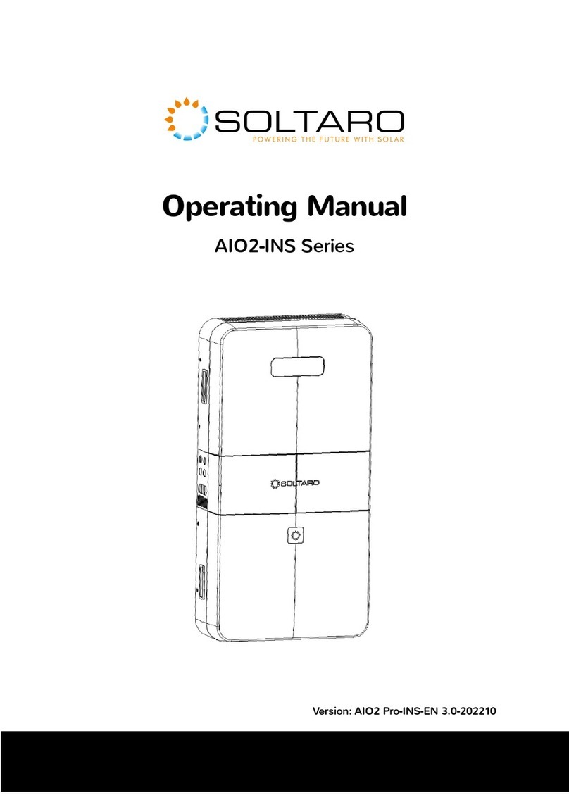
Soltaro
Soltaro AIO2-INS Series User manual

Soltaro
Soltaro SOLTARO-10K User manual
Soltaro
Soltaro AIO2-BTLV Series User manual
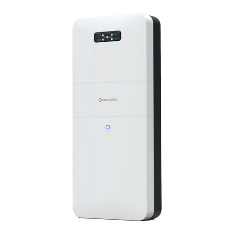
Soltaro
Soltaro AIO2 Owner's manual
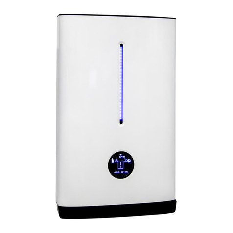
Soltaro
Soltaro Hyper Series User manual
Soltaro
Soltaro Life04 Series User manual
