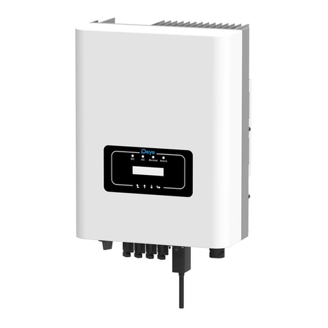
Soltaro SOLTARO-10K User manual

PV Grid Tie Inverter
Installation and Operation Manual
Ver 1.0
SOLTARO Three Phase Inverter
Please record the serial number of your inverter and quote this when you contact us.
Soltaro Pty Ltd
1/21 Hugo Place Mansfield QLD 4122, Australia
CSoltaro Pty Ltd
S
O
L
T
A
R
O
POWERING
THE FUTUREWITH SOLAR
S
O
L
T
A
R
O
POWERING
THEFUTUREWITH SOLAR

1. Introduction
2. Safety Instructions
2.1 Safety Symbols
2.2 General Safety Instructions
2.3 Notice For Use
3. Overview
3.1 Front Panel Display
3.2 LED Status Indicator Lights
3.3 Keypad
3.4 LCD
4. Installation
4.1 Selecting Location for the Inverter
4.2 Mounting the Inverter
4.3 Electrical Connections
5. Start and Stop
5.1 Start the Inverter
5.2 Stop the Inverter
Contents
3
5
5
5
6
7
7
7
8
8
9
9
11
12
13
15
17
………………………
………………………………………
………………………………………………
………………………………
………………………
……………………………………………
…………………………………………………
………………………………………………
…………………
………………………………
……………………………
…………………………………
……………………………………………
……………………………………
……………………………………
1.2 Packaging 4
……………………………………
1.1 Introductions 3
……………………………………
6. Operation
6.1 Main Menu
6.2 Information
19
19
19
20
20
22
…………………………………………………
……………………………………………
……………………………………………
4.3.1 Assemble PV input connector of the Inverter
20
…
4.3.2 Assemble the grid side connector of the Inverter
4.3.3 Connect DRM to the COM1 of the inverter ……
6.2.1 Lock screen ……………………………………
………………………………………………
…………………………………
22
22
6.3 Settings
6.3.1 Set Time
………………………………………………
……………………………………

Optional
1. Introduction
Figure 1.1 Front side view
Figure 1.2 Bottom side view
Contents
7. Maintenance
8. Trouble Shooting
9. Specifications
35
34
34
33
33
29
29
28
28
28
27
27
26
26
25
25
25
24
24
24
24
23
23
22
35
40
………………………………………………
…………………………………………
……………………………………………
SOLTARO three phase series PV inverters could transfer DC power from PV panels into AC
power and feed into grid. There are 6 models for SOLTARO three phase inverter.
SOLTARO-3P5K,SOLTARO-6K, SOLTARO-10K, SOLTARO-15K are used for 380/400V
three phase grid system, SOLTARO-20K-HV is used for 480V three phase grid system.
SOLTARO-6K-LV, SOLTARO-10K-LV are use for 208/220/240V three phase grid system.
All 6 models are transformerless topology grid tie PV inverter.
6.4 Advanced Info - Technicians Only
6.4.1 Alarm Message
6.4.3 Version
6.4.4 Daily Energy
6.4.5 Monthly Energy and Yearly Energy
6.5 Advanced Settings - Technicians Only
6.5.1 Select Grid Standard
6.5.2 Grid ON/OFF
6.4.2 Running Message
6.5.3 Clear Energy
6.4.7 Communication Data
6.4.8 Warn Message
6.4.6 Daily Record
6.5.5 Power Control
6.5.6 Calibrate Energy
6.5.4 Reset Password
6.5.7 Special settings
6.5.8 STD. Mode Settings
6.5.9 Restore Settings
6.5.11 Reset HMI
6.5.12 Debug Parameter
6.5.10 HMI Updater
6.3.2 Set Address …………………………………
………………………………
……………………………
………………………………
………………………
………………………………………
…………………………………
………………………………
……………
……………
………………………
…………………………………
…………………………………
……………………………
……………………………
………………………
……………………………
………………………………
…………………………………
………………………………
…………………………………
………
34
6.5.13 FAN Test
34
6.5.14 Power Parameter
…………………………
…………………………
………………………………………
.3.
S
O
L
T
A
R
O
POWERING
THEFUTUREWITH SOLAR

2.Safety Instructions
.5.
2.2 General Safety Instructions
WARNING:
Electrical installations must be done in accordance with the local and national
electrical safety standards
CAUTION:
CAUTION, RISK OF ELECTRIC SHOCK symbol indicates important safety
instructions, which if not correctly followed, could result in electric shock.
CAUTION:
CAUTION, HOT SURFACE symbol indicates safety instructions, which if not
correctly followed, could result in burns.
NOTE:
NOTE symbol indicates important safety instructions, which if not correctly
followed, could result in some damage or the destruction of the inverter.
2.1 Safety Symbols
Safety symbols used in this manual, which highlight potential safety risks and important
safety information, are listed as follows:
WARNING:
WARNING symbol indicates important safety instructions, which if not
correctly followed, could result in serious injury or death.
Improper use may result in potential electric shock hazards or burns. This manual
contains important instructions that should be followed during installation and
maintenance. Please read these instructions carefully before use and keep them for
future reference.
WARNING:
Please don’t connect PV array positive(+) or negative(-) to the ground, it could
cause serious damage to the inverter.
.4.
1.2 Packaging
When you receive the inverter, please check if all the parts listed below are included:
1. Introduction
Part NO.
1
Description
PV grid tie inverter
2
Wall mounting bracket
3
Locking screws
5 AC connector
6DC connectors
Manual
7
Number
1
1
2
1
4 pairs(2 for SOLTARO-6K)
1
Table 1.1 Material list
4
56
S
O
L
T
A
R
O
POWERING
THEFUTUREWITH SOLAR
PV Gr id Tie Inv erter
Ins talla tion an d Opera tion Ma nual
Ver 1.0
SOLTARO Three Phase Inverter
CSolt aro P ty Ltd
S
O
L
T
A
R
O
POWERING
THEFUTUREWITH SOLAR
S
O
L
T
A
R
O
POWERING
THEFUTUREWITHSOLAR

3. Overview
3.1 Front Panel Display
Figure 3.1 Front Panel Display
3.2 LED Status Indicator Lights
There are three LED status indicator lights in the front panel of the inverter. Left LED:
POWER LED (red) indicates the power status of the inverter. Middle LED: OPERATION
LED (green) indicates the operation status. Right LED: ALARM LED (yellow) indicates
the alarm status. Please see Table 3.1 for details
Description
The inverter can detect DC power
No DC power or low DC power
The inverter is operating properly.
The inverter has stopped to supply power.
The inverter is initializing.
Alarm or fault condition is detected.
The inverter is operating properly.
Status
ON
OFF
ON
OFF
OFF
ON
FLASHING
Light
POWER
OPERATION
ALARM
Table 3.1 Status Indicator Lights
2.Safety Instructions
2.3 Notice For Use
The inverter has been constructed according to the applicable safety and technical
guidelines. Use the inverter in installations that meet the following sepcification ONLY:
1. Permanent installation is required.
2. The inverter must be connected to a separate grounded AC group, to which no other
electrical equipment is connected.
3. The electrical installation must meet all the applicable regulations and standards.
4. The inverter must be installed according to the instructions stated in this manual.
5. The inverter must be installed according to the correct technical specifications.
6. To startup the inverter, the Grid Supply Main Switch (AC) must be switched on, before
the solar panel's DC isolator shall be switched on. To stop the inverter, the Grid Supply
Main Switch (AC) must be switched off before the solar panel's DC isolator shall be
switched off.
CAUTION:
The PV array (Solar panels) supplies a DC voltage when it is exposed to light.
CAUTION:
Risk of electric shock from energy stored in capacitors of the Inverter. Do not
remove cover until 5 minutes after disconnecting all sources of supply. Service
technician only. Warranty may be voided if any unauthorized removal of cover.
CAUTION:
The surface temperature of the inverter can reach up to 75℃ (167 F).
To avoid risk of burns, do not touch the surface when inverter is operating.
Inverter must be installed out the reach of children.
WARNING:
To reduce the risk of fire, branch-circuit over-current protective devices
(OCPD) are required for circuits connected to the Inverter.
The recommend rated trip current for AC breaker should be 25A for
SOLTARO-3P5K,SOLTARO-6K inverter, 32A for SOLTARO-10K,
SOLTARO-15K, SOLTARO-20K-HV inverter.
CAUTION:
Risk of electric shock. Do not remove cover. There is no user serviceable
parts inside. Refer servicing to qualified and accredited service technician.
.7..6.

4. Installation
4.1 Select a Location for the Inverter
3.3 Keypad
3.4 LCD
There are four keys in the front panel of the Inverter(from left to right):
ESC, UP, DOWN and ENTER keys. The keypad is used for:
Scrolling through the displayed options (the UP and DOWN keys);
Access to modify the adjustable settings (the ESC and ENTER keys).
3. Overview
The two-line Liquid Crystal Display (LCD) is located at the front panel of the Inverter,
which shows the following information:
Inverter operation status and data;
Service messages for operator;
Alarm messages and fault indications.
.8. .9.
To select a location for the inverter, the following criteria should be considered:
Figure 4.1 Recommend Installation place
To avoid over heating ambient air temperature MUST be considered when choosing the
inverter installation location. SOLTARO recommends using a sun shade minimizing direct
sunlight when the ambient air temperature around the unit exceeds 104°F/40°C.
Do not install in small closed spaces where air can not circulate freely. To avoid
overheating, always make sure the flow of air around the inverter is not blocked.
Exposure to direct sunlight will increase the operational temperature of the inverter and
may cause output power limiting. SOLTARO recommends inverter installed to avoid
direct sunlight or raining.

For 1 or more inverter installed, a minimum 12in clearance should be kept between
each inverter or other object. The bottom of the inverter should be 20in clearance to
the ground.
Visibility of the LED status indicator lights and the LCD located at the front panel of
the inverter should be considered.
Adequate ventilation must be provided if the inverter is to be installed in a confined space.
NOTE:
Nothing should be stored on or placed against the inverter.
500mm
500mm
500mm
500mm 500mm
500mm
500mm
Figure 4.1 Inverter Mounting clearance
4. Installation4. Installation
Inverter should be mounted in a vertical position as shown in Figure 4.3. The steps to
mount the inverter on the wall are given as follows:
1. Locate the wall studs in the desired location and align the wall mount bracket over
the studs. Mark the mounting holes. For masonry walls, the mounting holes should be
for a suitable dynabolt type mounting system.
2. MAKE SURE BRACKET IS horizontal. Ensure that the A, B, C, and D mounting holes
(in Figure 4.3) are aligned with the wall's most secure points (e.g. wall studs in case of
clad building materials).
4.2 Mounting the Inverter
Please use suitable fixings for wall type (e.g. use dynabolts for brick, masonry, etc).
Figure 4.3 Inverter Mounting
WARNING:
Bracket must be mounted vertically on a vertical wall surface.
Bracket
Stainless steel screw
Inverter
Suitable fixing screws
.10. .11.
Figure 4.2 Inverter Mounting clearance
Install vertically with a maximum incline of +/- 5°.If the mounted inverter is tilted to an
angle greater than the maximum noted, heat dissipation can be inhibited, and may
result in less than expected output power.
S
O
L
T
A
R
O
POWERING
THEFUTUREWITHSOLAR
S
O
L
T
A
R
O
POWERING
THEFUTUREWITHSOLAR

4. Installation4. Installation
AB
CD
Inverter
E F
4.3 Electrical Connections
The Inverter is designed for electrical connection without removing the cover. The meaning
of the symbols located at the bottom of the inverter are listed in Table 4.1.All electrical
installations must be in accordance with all local and national electrical codes.
Table 4.1 Terminals
+
-
Positive DC input terminal
Negative DC input terminal
DC 1
Positive or negative DC 1 input terminal
DC 2
Positive or negative DC 2 input terminal
DC SWITCH Switch of DC input terminals(optional)
COM Communication connection equipment terminal (Optional)
GRID Grid wires connection equipment terminal
3. Carefully hang the inverter on the upper part of the wall mount bracket by fitting the
hooks into the slot of the bracket. Use stainless steel screws at holes E and F
(in Figure 4.4) to secure the mounting hooks to the rear of the inverter.
Figure 4.4 Wall Mount Bracket
The electrical connection of the inverter must follow the steps listed below:
Switch the Grid Supply Main Switch (AC) OFF.
Switch the DC Switch OFF.
Before connection, please make sure the polarity of the output voltage of PV array
matches the“DC+”and “DC-”symbols.
Before connecting inverter, please make sure the PV array open circuit voltage is
within the limit of the inverter
Please don’t connect PV array positive or negative pole to the ground, it could
cause serious damages to the inverter
Figure 4.5 DC+ Connector Figure 4.6 DC- Connector
Please use qualified DC cable for PV system.
.12.
Maximum 1000Voc for
SOLTARO-3P5K SOLTARO-6K SOLTARO-10K
SOLTARO-15K SOLTARO-20K-HV
4.3.1 Assemble PV input connector of the Inverter
.13.

4. Installation4. Installation
iii) Crimp the contact pin to the wire using a proper wire crimper as shown in Figure 4.9
Figure 4.9 Crimp the contact pin to the wire
iv) Insert the contact pin to the top part of the connector and screw up the cap nut to
the top part of the connector (as shown in Figure 4.10).
The steps to assemble the DC connectors are listed as follows:
I) Strip off the DC wire for about 7mm, Disassemble the connector cap nut (see Figure 4.7).
ii) Insert the wire into the connector cap nut and contact pin as shown in Figure 4.8.
Figure 4.7 Disassemble the Connector Cap nut
Figure 4.8 Insert the Wire into the Connector Cap nut and contact pin
Figure 4.10 Connector with Cap nut Screwed on
Figure 4.11 Connect the DC Connectors to the Inverter
v) Then connect the DC connectors to the inverter. Small click will confirm connection
(as shown in Figure 4.11).
2
For all AC connections, 2.5- 6mm 105 ℃ cable is required to be used. Please make sure
the resistance of cable is lower than 1.5 ohm. If the wire is longer than 20m, it's
2
recommended to use 6mm cable.
WARNING:
There are symbols marked inside the connector ( see
Figure4.12), the Line wire of grid must be connected to “L” “1” “2” terminal; the
Earth wire of grid must be connected to“ ”; it is recommended that the
Neutral wire of grid is connected to“N”terminal (not required)
“L” “1” “2” “N” “ ”
.14.
4.3.2 Assemble the grid side connector of the Inverter
.15.

4. Installation4. Installation
Figure 4.12 AC Grid Terminal Connector
Figure 4.13 AC Grid Terminal Connector Inside
The steps to assemble the AC grid terminal connectors are listed as follows:
Figure 4.14 Connect Wires to the Grid Terminal
Each SOLTARO three phase inverter is supplied with an AC grid terminal connector, which is
in Figure 4.12.
L
N
12
G
a) Strip the end of AC wire about 8mm, Insert the cable through the jacket and cap
nut of connector, then insert the wires to the grid terminal and tighten the screws
on the connector (as shown in Figure 4.13). Please try to pull out the wire to make
sure it is well connected.
Figure 4.15 Tighten up the cap on the terminal
c) Connect the AC grid terminal connector to the inverter. Small click will confirm
connection (as shown in Figure 4.16).
Figure 4.16 Connect AC Terminal Connector to the inverter
b) Assemble the connector and tighten up cap on the terminal (as shown in Figure 4.14).
.16.
Figure 4.17 Connect DRM to the COM1 of the inverter
4.3.3 Connect DRM to the COM1 of the inverter
DRMisrequiredbyAS4777.2:2015,ConnectioninverterwithDRMmodulewillachieve
DRMfunctionrequiredbygrid. Please connect inverter COM port with DRM INV port.
For detail please see DRM manual.
.17.

5. Inverter monitoring Connection.
Figure 4.18 Wi-Fi communication function
Internet
GPRS monitoring
Wi-Fi monitoring
Smart phone monitoring
PC monitoring
Web server
Router
Wi-Fi monitoring
Wi-Fi box
4. Installation
.18.
5.1 Start the Inverter
To start up the Inverter, it is important that the following steps are strictly followed:
1. Switch the Supply Main Switch (AC) ON first.
2. Switch the DC Isolator ON.
3. When both the DC and the AC grid sides supply to the inverter, it will be ready to
generate power. Initially, the inverter will check both its internal parameters and the
parameters of the AC grid, to ensure that they are within the acceptable limits. At the
same time, the green LED will flash and the LCD displays the information of
INITIALIZING.
4. After 30-180 seconds (depending on local requirement), the inverter will start to
generate power. The green LED will be on continually and the LCD displays
GENERATING.
WARNING:
Do not touch the surface when the inverter is operating. It may be
hot and cause burns.
5.2 Stop the Inverter
To stop the Inverter, the following steps must be strictly followed:
1. Switch the Grid Supply Main Switch (AC) OFF.
2. Wait 30 seconds. Switch off the DC switch or pull out the DC input cable. All the LEDs of
the inverter will be off in a minute.
5. Start & Stop
The inverter can be monitored by Wi-Fi or GPRS functions. All the communication functions are
optional (Figure 4.18), please refer to communication connection instructions.
For inverter connect with DRM, please connect communication cable or device to DRM COMM port.
.19.
S
O
L
T
A
R
O
POWERING
THEFUTUREWITHSOLAR
S
O
L
T
A
R
O
POWERING
THEFUTUREWITHSOLAR
S
O
L
T
A
R
O
POWERING
THEFUTUREWITHSOLAR

6. Operation
6.1 Main Menu
During normal operation, the display shows the power and the operation status alternately
with each screen lasting for 10 seconds (see Figure 6.1). Screens can also be scrolled
manually by pressing the UP and DOWN keys. Pressing the ENTER key gives access to
Main Menu.
Figure 6.1 Operation Overview
5 sec
Model name
Start
Power 9424W
01-01-2010 09:04
Status: Generating
01-01-2010 09:04
Information
Settings
Advanced Info.
Advanced settings
UP/DOWN
UP/DOWN
UP/DOWN
UP/DOWN or
auto-scroll
(10 sec)
Pressing the
ENTER key
gives access to
the main menu.
Pressing the
ESC key
calls back the
previous menu.
Main Menu
There are four submenus in the Main Menu (see Figure 6.1):
1. Information
2. Settings
3. Advanced Info.
4. Advanced Settings
6.2 Information
The SOLTARO three phase PV inverter main menu provides access to operational data and
information. The information is displayed by selecting "Information" from the menu and
then by scrolling up or down.
6. Operation
V_DC1 350.8V
I_DC1 5.1A
V_DC2 350.8V
I_DC2 5.1A
V_Grid 400.4V
I_Grid 8.1A
Status: generating
Power: 1488W
Grid Frequency
F_Grid 50.06Hz
Total Energy
0258458 kwh
This Month: 0123kwh
Last Month: 0123kwh
Today: 02kwh
Yesterday: 01kwh
10 sec
10 sec
10 sec
10 sec
10 sec
10 sec
10 sec
10 sec
V_DC1: Shows input 01 voltage value.
I_DC1: Shows input 01 current value.
V_DC2: Shows input 02 voltage value.
I_DC2: Shows input 02 current value.
V_Grid: Shows grid voltage value.
I_Grid: Shows grid current value.
Status: Shows status of the inverter.
Power: Shows output power value.
F_Grid: Shows frequency of grid value.
Total energy output value (since the last time
energy was cleared).
This Month: Total energy generated this month.
Last Month: Total energy generated last month.
Today: Total energy generated during this Day.
Yesterday: Total energy generated last Day.
Display Duration Description
Table 6.1 Information Indicator
.20.
10 sec
Work Mode:NULL
DRM Number:08 10 sec
Work Mode:The work mode of the inverter
DRM Number: the number of DRM which
connected to the inverter.
Inverter SN
00000000000000 Display series number of the inverter.
.21.

6. Operation
6.3 Settings
The following submenus are displayed when the Settings menu is selected:
1. Set Time
2. Set Address
6.3.1 Setting Time
This function allows time and date setting. When this function is selected, the LCD will
display a screen as shown in Figure 6.3.
NEXT=<ENT> OK=<ESC>
01-01-2010 16:37
Figure 6.3 Set Time
Press the UP/DOWN keys to set time and data. Press the ENTER key to move from one
digit to the next (from left to right). Press the ESC key to save the settings and return to
the previous menu.
6.3.2 Setting Address
YES=<ENT> NO=<ESC>
Set Address: 02
Figure 6.4 Set Address
Press the UP/DOWN keys to set the address. Press the ENTER key to save the settings.
Press the ESC key to cancel the change and return to the previous menu.
This function is used to set the address of an inverter connected to PC for communication
purpose. The address number can be assigned from “01”to “99”(see Figure 6.4).
The default address number of SOLTARO three phase inverter is “01”.
6. Operation
.22.
Figure 6.2 Locks and Unlocks the Screen of LCD
(b)(a)
Pressing the ESC key returns to the Main Menu. Pressing the ENTER key locks
(Figure 6.2(a)) or unlocks (Figure 6.2 (b)) the screen.
6.2.1 Lock screen 6.4 Advanced Info - Technicians Only
1. Alarm Message
2. Running message
3. Version
4. Daily Energy
5. Monthly Energy
6. Yearly Energy
7. Daily Record
8. DSP Communication Data
9. Warning Message
The screen can be scrolled manually by pressing the UP/DOWN keys. Pressing the ENTER
key gives access to a submenu. Press the ESC key to returns to the Main Menu.
6.4.1 Alarm Message
The display shows the 100 latest alarm messages (see Figure 7.6). Screens can be scrolled
manually by pressing the UP/ DOWN keys. Press the ESC key to return to the previous
menu.
Alarm001: OV-G-V
Time: 27-11 Data: 7171
Figure 6.6 Alarm Message
NOTE:
Access to this menu is for fully qualified and accredited technicians only.
Entrance to “Advanced Info” and “Advanced Settings” req uires a password.
YES=<ENT> NO=<ESC>
Password:0000
Figure 6.5 Enter password
Select “Advanced Info.” from the Main Menu. The screen will require the password as below.
The default password is “0010". Please press “down” to move the cursor, press “up” to
change the digit.
.23.

.24.
6.4.2 Running Message
This function is for maintenance personnel to get running message such as internal temperature,
Standard NO. etc.
Screens can be scrolled manually by pressing the UP/DOWN keys.
6.4.3 Version
The screen shows the model version and the software version of the Inverter (see Figure 6.7).
Model: 08
Software Version: D20001
Figure 6.7 Model Version and Software Version
6.4.4 Daily Energy
The function is for checking the energy generation for selected day.
Press DOWN key to move the cursor to day, month and year, press UP key to change the digit.
Press Enter after the date is fixed.
2015-02-22: 051.3kWh
2015-02-23: 061.5kWh
Press UP/DOWN key to move one date from another.
6.4.5 Monthly Energy and Yearly Energy
The two functions are for checking the energy generation for selected month and Year.
Figure 6.8 Select date for daily energy
Figure 6.9 Daily energy
Figure 6.10 Select month for monthly energy Figure 6.11 Select year for yearly energy
YES=<ENT> NO=<ESC>
Select: 2015-02-23
YES=<ENT> NO=<ESC>
Select: 2015-02
YES=<ENT> NO=<ESC>
Select: 2015
Press DOWN key to move the cursor, press UP key to change the digit.
Press Enter after the month/year is fixed.
2015-02: 0510kWh
2015-01: 0610kWh
Press UP/DOWN key to move one date from another.
2015: 0017513kWh
2014: 0165879kWh
Figure 6.12 Month energy Figure 6.13 Yearly energy
6.4.8 Warning Message
Message00:
T: 27-11 D: 7171
6.4.7 Communication Data
The screen shows the internal data of the Inverter (see Figure 6.14), which is for service
technicians only.
01-05: 01 25 E4 9D AA
06-10: C2 B5 E4 9D 55
Figure 6.14 Communication Data
6.4.6 Daily Record
The screen shows history of changing settings. Only for maintenance personnel.
The screen shows the internal data of the Inverter (see Figure 6.15), which is for service
technicians only.
Figure 6.15 Warning message
.25.
6. Operation6. Operation

This function is used to select the grid's reference standard (see Figure 6.16).
YES=<ENT> NO=<ESC>
Standard:AUS-Q-0.8
Figure 6.16
6.5.1 Selecting Standard
6.5 Advanced Settings - Technicians Only
Select Advanced Settings from the Main Menu to access the following options:
1. Select Standard
2. Grid ON/OFF
3. Clear Energy
4. New Password
5. Power Control
6. Calibrate Energy
7. Special Settings
8. STD. Mode Settings
9. Restore Settings
10. Updater
11. Restart HMI
12. Debug Parameter
13. Fan test
14. Power Parameter
NOTE:
Access to this area is for fully qualified and accredited technicians only.
Please follow 6.4 to enter password to access this menu.
Selecting the “User-Def” menu will access to the following submenu (see Figure 6.17).
Figure 6.17
OV-G-V1: 260V
OV-G-V1-T: 1S
6.5.2 Grid ON/OFF
Grid ON
Grid OFF
Figure 6.18 Set Grid ON/OFF
Screens can be scrolled manually by pressing the UP/DOWN keys. Press the ENTER key
to save the setting. Press the ESC key to return to the previous menu.
NOTE:
The " User-Def" function can be only used by the service engineer and
must be allowed by the local energy supplier.
Below is the setting range for “User-Def”. Using this function, the limits can be changed
manually.
Press the UP/DOWN keys to scroll through items. Press the ENTER key to edit the highlighted
item. Press the UP/DOWN keys again to change the setting. Press the ENTER key to save the
setting. Press the ESC key to cancel changes and returns to the previous menu.
6.5.3 Clear Energy
These two functions are applicable by maintenance personnel only, wrong
operation will prevent the inverter from working properly.
This function is used to start up or stop the power generation of the inverter. (see Figure 6.18).
OV-G-V1: 410---530V OV-G-F1: 50.2-53Hz(60.2-63Hz)
OV-G-V1-T: 0.1---9S OV-G-F1-T: 0.1---9S
OV-G-V2: 430---580V OV-G-F2: 51-53Hz(61-63Hz)
OV-G-V2-T: 0.1---1S OV-G-F2-T: 0.1---9S
UN-G-V1: 300---360V UN-G-F1: 47-49.5Hz(57-59.5Hz)
UN-G-V1-T: 0.1---9S UN-G-F1-T: 0.1---9S
UN-G-V2: 230---330V UN-G-F2: 47-49Hz(57-59Hz)
UN-G-V2-T: 0.1---1S UN-G-F2-T: 0.1---9S
.26. .27.
6. Operation6. Operation

.28.
Enter the current password before setting a new password. Press the DOWN key to move the
cursor, Press the UP key to change the digit. Press the ENTER key to execute the setting.
Press the ESC key to return to the previous menu.
6.5.4 New Password
Figure 6.19 Set new password
YES=<ENT> NO=<ESC>
Password: 0000
6.5.5 Power Control
1. Set output power 2. Set Reactive Power 3. Out_P With Restore
4. Rea_P With Restore 5. Select PF Curve
This function is applicable for maintenance personnel only, wrong settings
will prevent the inverter from reaching maximum power.
Maintenance or replacement could clear or cause a different value for total energy. Use this
function to allow user to revise the value of total energy to the same value as before. If
the monitoring website is used the data will be synchronous with this setting automatically.
(see Figure 6.20).
Press the DOWN key to move the cursor, Press the UP key to revise the value. Press the
ENTER key to execute the setting. Press the ESC key to return to the previous menu.
6.5.6 Calibrate Energy
Figure 6.20 Calibrate energy
YES=<ENT> NO=<ESC>
Energy:0000000kWh
Special settings have the submenu shown below:
6.5.7 Special settings
1. Grid Filter Set 2. Relay_Protect Set 3. ILeak_Protect Set
4. Ground_Protect Set 5. GRID INTF.02 Set 6. Multiple MPPT Set
7. Voltage MPPT Set 8. LVRT Set 9. IgZero_COMP. Set 10. PI Set
This function is applicable by maintenance personnel only.
6.5.8 STD. Mode Settings
1. Working Mode Set
2. Power Rate Limit
3. Freq Derate Set
4. 10mins Voltage Set
5. Initial Settings
STD. Mode Settings have the submenu shown below:
This function is applicable by maintenance personnel only.
6
.29.
6. Operation6. Operation

SOLTARO SOLTARO inverter support 6 working mode in this menu:
1. Null 2. Volt-watt 3. Volt-Var 4. Fixed-PF 5. Reac-Power 6. Power-PF
6.5.8.1 Working Mode Set
3. Volt-var
Inverter will generate reactive power when voltage changes.
This function is applicable by maintenance personnel only, wrong operation
will prevent the inverter from reaching maximum power.
1. Null (Default setting)
Inverter not under any of below working mode.
The default setting of working mode is Null.
2. Volt-Watt
Inverter will limit output power when voltage changes.
6. Operation6. Operation
4. Fixed-PF
Inverter can set power factor from 0.8…1…08.
Figure 6.21 Volt-VAR
Voltage1:210V
Voltage2:360V
5. Reac-Power
Set reacive power (0, 60%), Default 0, Resolution 1%.
6. P-Factor
Inverter will change power factorr when output power changes.
This function is applicable by maintenance personnel only, wrong operation
will prevent the inverter from reaching maximum power.
YES=<ENT> NO=<ESC>
Power Factor:+1.00
Figure 6.22 Fixed-PF
.30. .31.
5. Volt-Var
Set Voltage1: 207-220V, Default 207V
Set Voltage2: 216-230V, Default 220V
Set Voltage3: 235-255V, Default 250V
Set Voltage4: 244-265V, Default 255V
Set Leading: 0~+60%, Default +30%
Set Lagging: 0~-60%, Default -30%
Set Voltage1: 207-220V, Default 207V
Set P_Limit1: 20%-100%, Default 100%
Set Voltage2: 216-230V, Default 220V
Set P_Limit2: 20%-100%, Default 100%
Set Voltage3: 235-255V, Default 250V
Set P_Limit3: 20%-100%, Default 100%
Set Voltage4: 244-265V, Default 255V
Set P_Limit4: 20%-100%, Default 100%
This function is not applied for AS4777.2 standard.

6.5.8.2 Power Rate Limit
This function is used for change Power Ramp-up rate. When inverter start up or input string
MPPT changes, inverter power ramp-up rate is limited in this menu.
The default setting is stop (disable).
The setting range from 10% to 600%, means inverter power change rate perminute.
Values are not allowed to change. If they are set, they may not conform to the UL1741SA
standard.
Figure 6.23 Power Rate Limit
Power Rate:016%
RateP_Sts-US:STOP
6. Operation6. Operation
Over frequency load shedding Fstart range 51~52Hz, default setting 52Hz
Fstop is not used here.
Press the Enter key to select the frequency.
Press Up/Down to set. Press ESC to save the settings.
Figure 6.25 Freq-Watt characteristic
f min f nom f start f maxf stop
100% of
Available
Power
0
Grid Frequency
6.5.8.4 10mins Voltage Set
Thisfunctionisusedforsetting10minsVoltage,thescreenisshownasbelow.
6.5.8.3 Freq Derate Set
The default setting of Freq Derate Set is 01 when you select the As4777 standard.
Figure 6.24 Freq Derate Set
Derate Mode:01
OV-F-Start:60.20Hz
.32. .33.
The10minsVoltagerangeis244~258Vandthedefaultsettingis248V.
6.5.8.5 Initial Settings
In initial settings it will allow each work mode from 6.5.8.1 to 6.5.8.4 back to default.
Figure 6.27 Initial Settings
Work Mode Default
Power Rate Default
YES=<ENT> NO=<ESC>
10mins Voltage: 255V
Figure 6.26 10mins Voltage Set
6.5.9 Restore Settings
Figure 6.28
Press the ENTER key to save the setting. Press the ESC key to return to the previous menu.
Restore Settingsresetstheinvertertofactorydefaults.Selectingwillshowthescreen
below:
This function is applicable to maintenance personnel only.
Are you sure?
YES=<ENT> NO=<ESC>
6.5.10 Updater
This function is applicable by maintenance personnel only.

HMI Current Ver.: 02
YES=<ENT> NO=<ESC>
6.5.11 Restart HMI
This function is using to reset HMI.
6.5.12 Debug Parameter
HMI Updater have the submenu shown below:
Press the ENTER key to save the setting.
Press the ESC key to return to the previous menu.
Debug Parameter as shown as below:
This function is applicable to maintenance personnel only.
Press the UP/DOWN keys to scroll through items. Press the ENTER key to set ,
Press the DOWN key to scroll and press the UP key to change the value.
Then press the ENTER key to save the setting. Press the ESC key to cancel
changes and returns to the previous menu.
Figure 6.29
6.5.13 FAN Test
This function is reserved for other series of SOLTARO inverter.
Do not use this function.
6.5.14 Power Parameter
This function is applicable to maintenance personnel only.
.34. .35.
6. Operation 7. Maintenance
SOLTARO three phase inverter does not require any regular maintenance. However, clean
the heat-sink will help inverter dissipating heat and increase the life time of inverter.
The dirt on the inverter can be cleaned with a soft brush.
CAUTION:
Do not touch the surface when the inverter is operating. Some parts may be hot
and cause burns. Turn OFF your inverter (refer to Section 5.2) and let it cool
down before you do any maintenance or cleaning of inverter.
The LCD and the LED status indicator lights can be cleaned with cloth if they are too
dirty to be read.
NOTE:
Never use any solvents, abrasives or corrosive materials to clean the inverter.
8. Trouble Shooting
The inverter is designed in accordance with the most important international grid-tied
standards and safety and electromagnetic compatibility requirements. Before delivering to
the customer, the inverter has been subjected to several tests to ensure its optimal operation
and reliability.
In case of failure, the LCD screen will display an alarm message. In this case, the inverter
may stop feeding into the grid. The failure descriptions and their corresponding alarm
messages are listed in Table 8.1:

.36.
8. Trouble Shooting
.37.
Alarms Cause Solution
• Input voltage low/missing
• Polarity reversed
• Main board damaged
No Information
(Blank Screen)
Test – DC switch OFF
• Check PV connections
• Check polarity
• Check voltage >120V Single, >350V three
Test – DC Switch ON
• Check voltage >120V Single, >350V three
• If DC voltage is “0” replace inverter
Initializing
(Inverter stuck
in this mode)
• Inverter is waiting for
driving signal
Test – DC switch OFF
• Check PV connections
• Check polarity
• Check voltage >120V Single, >350V three
Test – DC Switch ON
• Check voltage >120V Single, >350V three
• A cable may have been damaged or loosened
in shipping replace inverter
OV-G-V: Over
Grid Voltage
• Inverter detects grid
voltage as too high
Test – DC switch OFF
• Check AC at the inverter
• If AC measures high, adjust upper limit with
permission from utility
Test – DC Switch ON, full power
• Check AC at inverter test points
• Compare with LCD
• If AC measures high, cables between inverter
and interconnect are too small
• Check ampacity and voltage drop calculations
UN-G-V: Under
Grid Voltage
• Inverter detects grid
voltage as too low
Test – DC switch OFF
• Check AC at the inverter test points
• If AC measures low, adjust lower limit with
permission from utility
• Check LCD voltage reading, may be a bad
measurement circuit
Test – DC Switch ON
• Check grid standard
• Replace inverter
8. Trouble Shooting
Alarms Cause Solution
• Inverter detects grid
Frequency as too high
OV-G-F: Over
Grid Frequency
Test – DC switch OFF
• Check frequency at the inverter test points
• If Frequency measures high, adjust upper
limit with permission from utility
• Check LCD reading, may be a bad
measurement circuit
Test – DC Switch ON
• Check grid standard
• Replace inverter
NO-GRID • Inverter does not
detect the grid
Test – DC switch OFF
• Check AC at the inverter test points
• L-L, L-GND
• Do NOT tell me 240VAC
• Check LCD reading, may be a bad
measurement circuit
Test – DC Switch ON
• Check grid standard
• Replace inverter
OV-DC: DC
voltage is too
high
• Inverter detects High DCV
Test – DC switch OFF
• Check DC at the inverter test points
• If DCV is high, too many panels in the string
Test – DC Switch ON
• Check LCD reading, may be a bad
measurement circuit
• Replace inverter
OV-BUS: DC
BUS voltage is
too high
• Inverter detects High
DCV on internal bus
Test
• Measure DC and AC voltages
• Compare with LCD
• Replace Inverter
• Internal damage
• Wire came loose during shipping
UN-BUS: DC
BUS voltage is
too low
• Inverter detects low DCV
on internal bus
Test
• Measure DC and AC voltages
• Compare with LCD
• Replace Inverter
• Internal damage
• Wire came loose during shipping
This manual suits for next models
6
Table of contents
Other Soltaro Inverter manuals
Soltaro
Soltaro QENDERCORE User manual

Soltaro
Soltaro AIO2-INS Series User manual

Soltaro
Soltaro AIO2-BTLV Series User manual

Soltaro
Soltaro Hyper Series User manual

Soltaro
Soltaro Life04 Series User manual

Soltaro
Soltaro All-In-One ESS User manual
Soltaro
Soltaro AIO2-INS Series User manual

Soltaro
Soltaro AIO2 Owner's manual