APT250/APT500/APT1000 Operation Manual
7
True Soltec Co., Ltd.
5. Start Pull Test
1. Confirm that the cable clamper is at the
home position.
2. Push the terminal clamper open lever and
set a terminal to the terminal clamper.
Releasing the terminal clamper open lever
allows the terminal to be fixed.
3. Push the START button on the controller
panel.
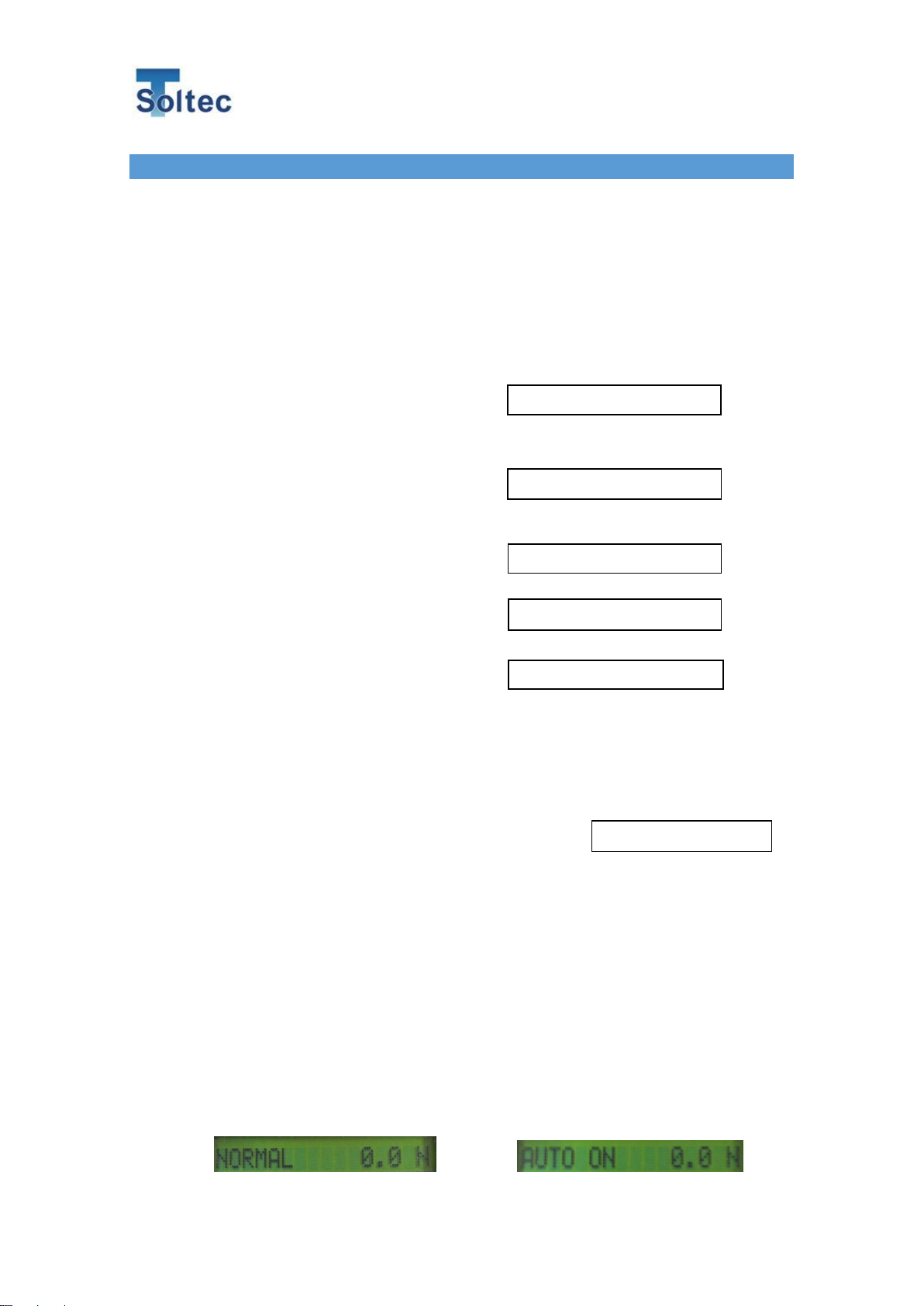
A pull test starts. The cable clamper
automatically goes backward while the cable
is caught in the clamp roller. The display
indicates a pull force in real time mode.
The controller detects a wire-strands
breakage automatically and stops the motor
rotation. The display indicates the peak value of its pull test.
Note:
The peak value remains on the display until the
ENTER or START button is pushed again.
When [ENTER] button is pushed:
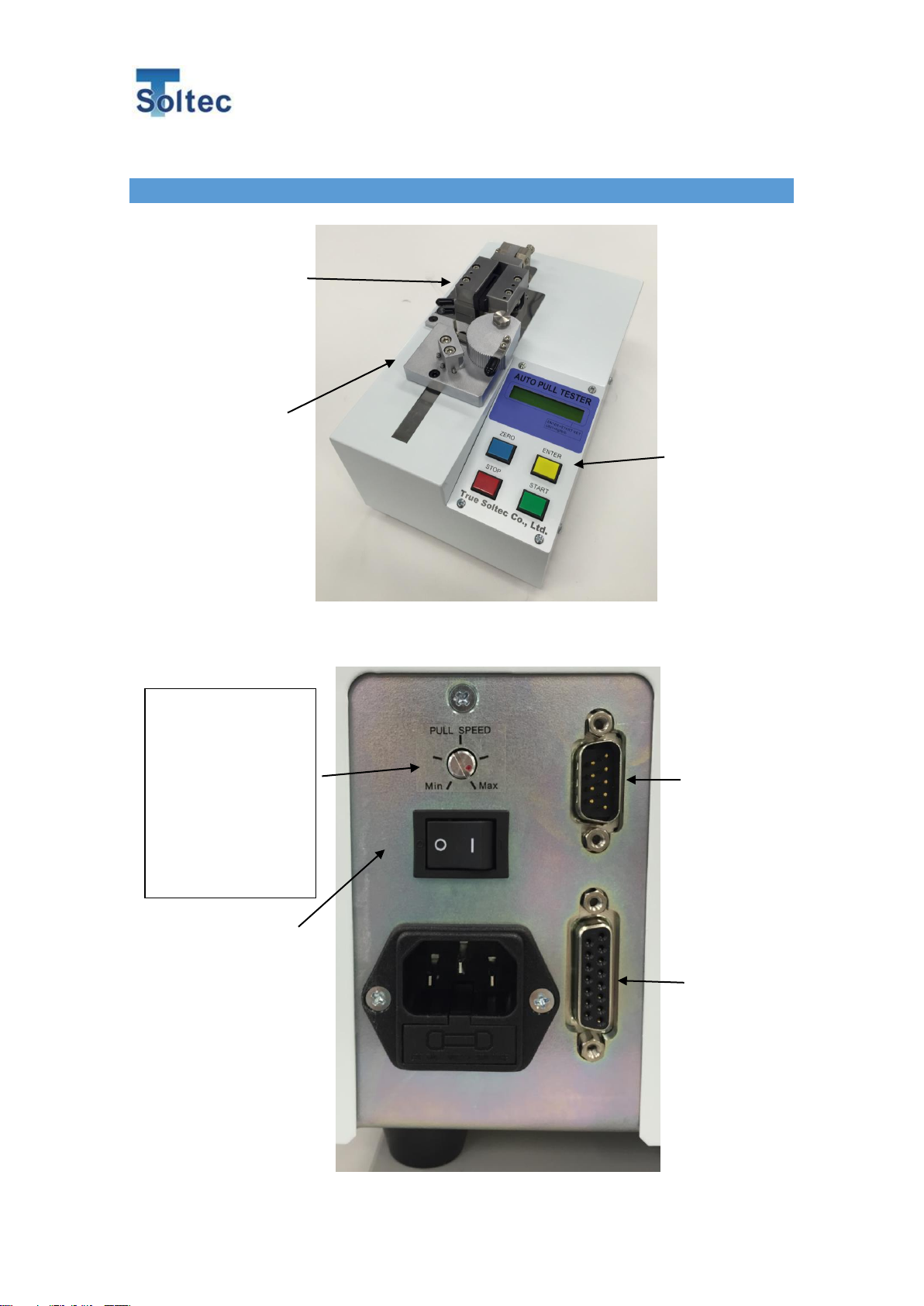
When the RS232C port on the back
panel is connected to PC, the peak load
value is sent to the PC.
When [START] button is pushed:
When the RS232C port on the back
panel is connected to PC, the peak load
value is not sent to PC.
Note:
When the RS232C port on the back
panel is not connected to PC, pushing
either of the ENTER button or START
button makes no differences.
The RS232C cable is not included in
the accessory. Use a D-SUB9pins
RS232C cross cable commercially available.
4. Push the ENTER or START button and the cable clamper goes back to the home
position, while the cable is automatically released. Remove it from the pull tester.
Wire strands breakage and Peak Value
Motor reverse rotation for home