CALIBRATION STATION INSTRUCTION MANUAL 1
1.0 Introduction
The ACS Calibration Station (CS) is diagnostic equipment designed to establish and maintain compliance of the ALCOLOCK
WR3 alcohol interlock Handset (HS). The following are the main components required for calibration:
Calibration Station (CS)
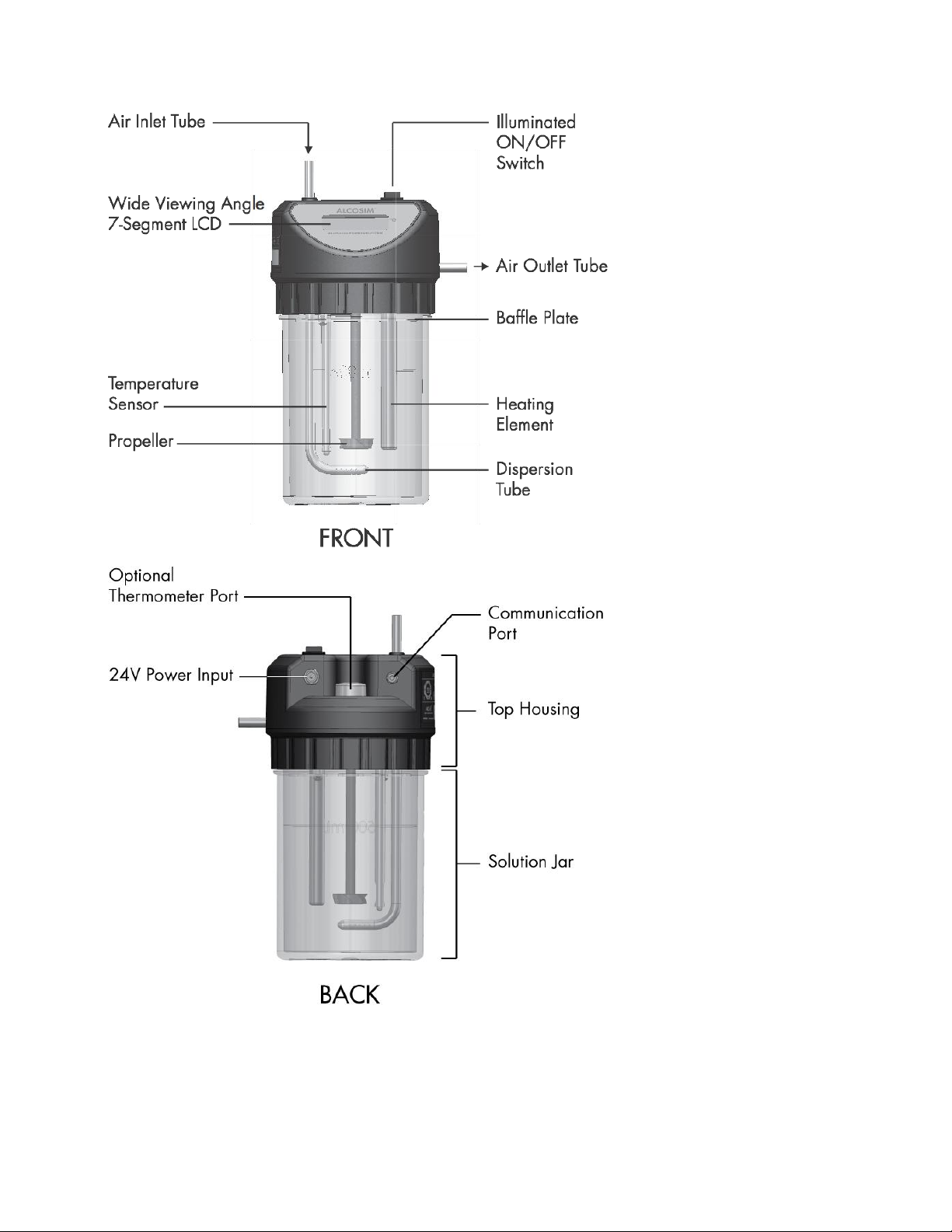
ALCOSIM breath alcohol simulator
INTERTRACKTM Enterprise Software (ITE)
For successful calibration, ensure that all components of the CS assembly are connected correctly. This manual will show you
how to safely connect and operate the CS assembly, and to calibrate the ALCOLOCK WR3 device.
ATTENTION!
General
This manual is for authorized service technicians only
Do not use ALCOSIM simulator with toxic liquids, flammable liquids or in explosive atmospheres
Use the product for its intended purpose only. Failure to do so will void the warranty and may cause injury and
damage the components
Avoid contact with the ALCOSIM heating element: CAUTION –Hot Surface
Only use parts supplied by Alcohol Countermeasure Systems
Do not open any enclosures. Doing so will void the warranty and may cause injury and damage the components
within. Contact your Service Provider if any hardware is not working
Ensure that the proper amount of solution is added; do not under-fill or over-fill the ALCOSIM simulator
If the ALCOSIM simulator overheats considerably beyond 34°C, turn it off and contact your Service Provider
Before use, inspect all components for visible cracks or damage. Failure to do so may cause injury or additional
damage
Do not force a cord into a port or input, as doing so will damage the components
Moisture, contamination and cleaning
The mouthpieces and all tubing must be completely dry before setup. Even slight condensation may disrupt the
procedure. Before beginning a calibration, make sure that all moisture has been completely removed from the
ALCOSIM simulator
The ALCOSIM jar must be completely clean and dry before you apply the alcohol reference solution. Remove the
ALCOSIM top housing before cleaning the solution jar
If liquid spills onto the CS or any other components, remove liquid with a cloth and allow the CS to dry
thoroughly. If there is substantial moisture damage, keep all components powered off and contact your Service
Provider
To clean the CS and ALCOSIM simulator: use a water dampened cloth to remove dirt or dust from the surface, and
allow it to dry thoroughly. Do not use cleaning products on the surface, as doing so may cause damage
After drying, remove all cloths or paper towels from the UCS and its components
Power
Check that the ALCOSIM simulator power ratings conform to the local supply rating
Power off the ALCOSIM simulator after use
When assembling, disassembling or preparing ALCOSIM simulator for use, ensure that it is not plugged into an
electrical outlet until you have been instructed to do so
Do not switch on the ALCOSIM simulator and CS until instructed
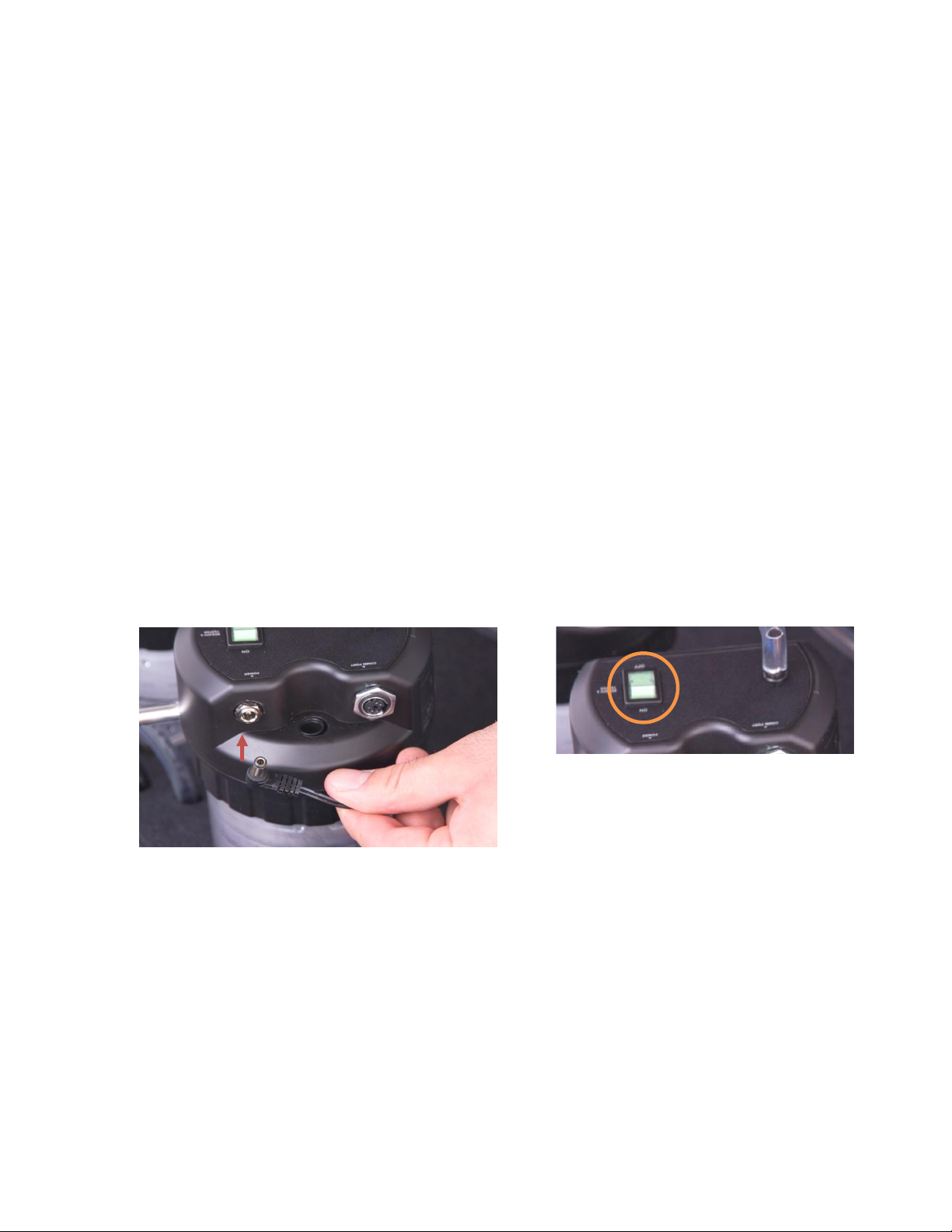
Do not plug in the ALCOSIM simulator and CS power cables until instructed
If the ALCOSIM was powered on, wait 15 minutes for the components to cool off before removing the top housing
Never open the ALCOSIM top housing when the simulator is switched on or plugged in
Do not disconnect any components while calibration is in progress
Failure to follow these instructions may result in injury or may damage the devices
Alcohol reference solution
Keep away from eyes. In case of contact, flush eyes with water. If irritation continues, contact your local poison
control centre
Do not ingest. In case of ingestion, do not induce vomiting. Contact your local poison control centre
Do not use a solution bottle with a broken seal, or a solution bottle that has expired
Keep at room temperature. Do not freeze or refrigerate
It is safe to dispose of alcohol reference solution in the drain. Refer to your local environmental regulations for
more information about safe disposal amounts