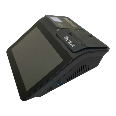
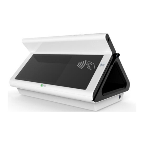
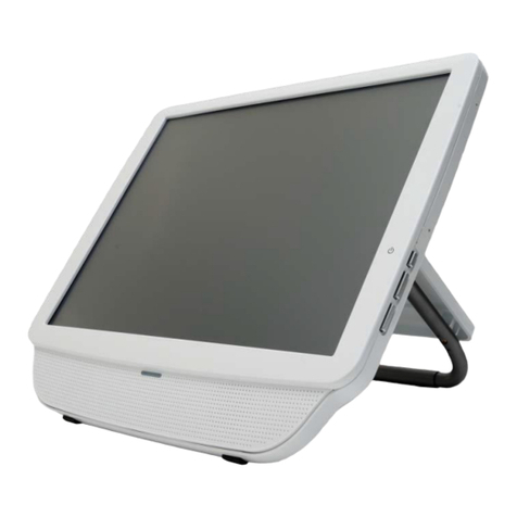
Solux AX1 User manual

A;$; Maintenance Manual

Catalogue
1 A;$; introduction........................................................................1
1.1 The technical specifications:......................................................2
1.2 Product description ....................................................................3
1.2.1 Appearance ......................................................................3
1.2.2 IO ports ............................................................................5
2 Machine Assembly ...............................................................................6
2.1 Disassembling machine .............................................................6
2.2 Dismantle the HDD ...................................................................9
2.3 Install the MSR ........................................................................10
2.4 Install the Customer Display....................................................11
2.4.1 Mounting the VFD Customer Display ...........................11
2.4.2 Mounting the 2nd Display..............................................11
2.5 Wall Mounting .........................................................................12
2.6 Installation of Mini PCI-E Equipment.....................................13
3 Main Component Technical Specifications ........................................14
3.1 Motherboard ............................................................................14
3.2 LCD .........................................................................................21
3.3 Touch Screen............................................................................22
3.4 Power Adapter .........................................................................23
3.5 3G module ...............................................................................24
3.6 MSR.........................................................................................26
3.7 WIFI.........................................................................................27
3.8 Internal Cables .........................................................................28
3.8.1 LVDS cable ....................................................................28
3.8.2 SATA cable.....................................................................28
3.8.3 Inverter cable .................................................................28
3.8.4 MSR cable......................................................................28
3.8.5 Serial port cable .............................................................29
3.8.6 Touch screen USB cable ................................................29
3.8.7 Interface board FPC cable..............................................29
3.8.8 Switch cable...................................................................29
3.8.9 Indicator cable................................................................30
4 System Setting ....................................................................................31
4.1 System diagram .......................................................................31
4.2 The BIOS Descriptions and Settings .......................................32
4.3 Software Installation and Settings ...........................................36
4.3.1 Chipset driver.................................................................36
4.3.2 VGA driver.....................................................................36
4.3.3 LAN driver.....................................................................36
4.3.4 Audio driver ...................................................................36
4.3.5 Touch screen driver........................................................36
4.3.6 WIFI driver ....................................................................36

4.3.7 Setup the touch screen....................................................36
4.3.8 Setup the MSR ...............................................................38

1
1 A;$; introduction
A;$;, developed by 6ROX[ with ten years experience of commercial
POS systems, is an innovation of traditional POS and KIOSK design. It
contains the full functions which a mainstream product has and can
satisfy the demands of commercial and related industry, for example,
cashing function in retail business, catering industry and self-service. It
has high configuration, multi-functional, low power consumption and
high reliability characteristics. It is widely used in shopping center,
department stores, supermarkets, shops, convenience stores, hotels,
restaurants and commercial enterprises, also used in places need
self-service, like telecommunications, banks, postal services, airport and
governments.
A;$; is an innovational solution of POS (point of sale) and
Kiosks. It uses upper cable management design into system to keep
simply cabling; Ship with the latest Intel Atom processor of high
performance for low power consumption; The touch screen and hard
disk are easy to remove for quick maintenance; Aluminum housing
guarantees efficient heat elimination and steady performance;
Streamline design offers artistic appearance; Modular design can expand
peripheral applications easily; Waterproof structure design for spill
proof; Fan free structure for harsh environment.

2
1.1 The technical specifications:
Model AX AX
CPU D525 1.8GHz D425 1.8GHz
Chipset Intel NM10, with max TDP 2.1W
Memory 4GB DDR3 2GB DDR3
Graphic
Interface
Integrate Intel GMA 3150 graphic core,
support DX9.0c
1*LVDS, 1*VGA
Storage 2.5'' HD, SATAII; SSD optional
LCD 15'' TFT 1024*768 resolution
Touch Screen 5 wires resistive
Audio
Realtek ALC662 5.1 Channel HD Audio
Codec
Line-in/Line-out (onboard header)
Power DC 12V/5A
USB 4*USB, 1*USB/+12V
RS232
6*RS232
(COM3 1pin&9pin 12V or
5V, set by BIOS)
Others
1*LPT
1*KB/MS
1*VGA
1*Drawer
2* Audio Jack
Ethernet
Realtek 8111DL PCI-E
Gigabyte Ethernet Controller
1*10/100/1000M
Port
OS
Windows2000,XP,
XPE,Win7,WEPOS,
POS Ready 2009
Linux
Dimensions(W)*(D)*(H)(mm)
370 * 247 *325 max
Customer display(Optional) 2*20 VFD or LCD
MSR(Optional) 3 tracks
WiFi(Optional) IEEE802.11/n
3G Module(Optional) WCDMA or CDMA2000

3
1.2 Product description
1.2.1 Appearance
Front view
NO. DESCRIPTION
1 15-inch TFT LCD and Touch screen
2 Magnet Stripe Reader(Optional)
3 Power LED and HDD LED

4
Rear view
NO.
DESCRIPTION
1 Cable Cover
2 HDD Cover
3 Hinge Cover
4 Base
5 The hole for cables
6 Power Switch
7 Speaker(Optional)

5
1.2.2 IO ports
NO.
DESCRIPTION MARK
1 AC adapter jack
2 PS2 KB
3 PS2 MS
4 Parallel port (LPT1)
5 VGA port
6 USB 1&2&3&4
7 Power USB 1 12V
8 Power USB 2 (Optional) 12V
9 RJ-45 LAN port
10 Microphone
11 Line-out
12 +12V Output jack OUT 12V
13 COM1 port COM1
14 COM2 port COM2
15 COM3 port COM3
16 COM4 port(with 12V) COM4
17 Cash Drawer Port 1 CD1
18 Cash Drawer Port 2 (Optional) CD2
19 Wi-Fi Antennae(Optional)
NOTE
:
The default setting of customer display port is
COM4.The 1 or 9 pin of COM3 can set 12V or 5V by BIOS.

6
2 Machine Assembly
2.1 Disassembling machine
Step 1, Remove the cable cover
Step 2; Open the hard disk cover, uninstall screws, pull out hard disk.

7
Step 3, Unload eight screws which fixed the shell.
Step 4; Open two buckles on the right side, then dismantling the front
shell and the touch screen

8

9
2.2 Dismantle the HDD
1、Dismantle the
HDD cover, and
find the HDD
bracket.
2、Remove the
screw of the
HDD bracket.
3、Pull out the
HDD bracket.

10
2.3 Install the MSR
1、Put the MSR
into the slot and
move down to
fix.
2、Fix the MSR
with 2 M3*8
supplied screws.
3、Connect the
data wire of
MSR to the port
under the HDD
bracket. Then
cover it.

11
2.4 Install the Customer Display
2.4.1 Mounting the VFD Customer Display
1、Fix the display
with 4 M4*8.5
supplied screws.
2、Connect the
customer display
to customer
display port
COM4 on the
machine.
2.4.2 Mounting the 2nd Display
1、Fix the display
with 4 M4*8.5
supplied screws.
2、Connect the
2nd LCD display
to the VGA port
and +12V output
jack separately.
3、When set up
the touch screen
on the 2nd LCD
display, connect
the control line
to the USB port.

12
2.5 Wall Mounting
1、Fix the holder
on the rear of the
machine with 4
M4*8.5 screws.
2、Mounting the
bracket on the
wall or other
place with 4
screws. Our
bracket meet the
standard VESA.
The specification
is 100 * 100
(mm).
3、Put the holder
into bracket,and
fix them with 2
M3*4 screws.

13
2.6 Installation of Mini PCI-E Equipment
Step1, move the equipment into the Mini PCI-E socket.
Step2, Use screws column fix equipment.

14
3 Main Component Technical Specifications
3.1 Motherboard
The motherboard AX1 AX2 use is SV1-D5216 and SV1-D4216.
The component No. of SV1-D5216 is 12110328
The component No. of SV1-D4216 is 12110329
Model SV1-D5216 SV1-D4216
CPU
Intel Atom D525
1.8GHz BGA CPU
With IMC,GPU and IIO
integrated
Intel Atom D425
1.8GHz BGA CPU
With IMC,GPU and IIO
integrated
Chipset Intel NM10,with max TDP 2.1W
Graphic
Interface
Integrate Intel GMA 3150 graphic core, Support
DX9.0c
1*LVDS,1*VGA
Memory Support DDR3 800/667MHz
2*SO-DIMM slot, Maximum voltage of 4 GB
Storage Intel Serial ATA2(3 Https)controller
2*Serial ATA ports
Ethernet
Realtek 8111DL PCI-E Gigabyte Ethernet
Controller
Support 10/100/1000 Mbps with RJ45
Audio Realtek ALC662 5.1 Channel HD Audio Codec
Support Line-in/Line-out Ports(onboard header)
Expand
Slot 1*Mini PCI-E
Other
Port
6*COM(1 DB9,5 internal)
8*USB2.0(4 on panel,4 internal)
1*PS/2 keyboard and mouse ports(internal)
1*Microphone/Audio Output(internal)
1*CPU fan socket
1*System fan socket
1*LPT
Power
Supply DC12V
Factor Mini ITX

15

16
The mother board pins definition
[1] PS/2 Keyboard and Mouse Header(6*1 Pin 2.00 mm)
[2] Single Channel LVDS Interface (1.25 mm)
[3] Control J20.1 ~ J20.4 (3*1Pin 2.00 mm)
[4] LVDS Backlight Control Header(5*1 Pin 2.00 mm)
[5] Control JP4.4 (3*1 Pin 2.00mm)
[6] CPU Fan (2.00 mm)

17
[7] System Fan (2.00 mm)
[8] Amplifier Header(5*2 Pin 2.54 mm)
[9] Front Panel Header(5*2 Pin 2.54 mm)
[10] SATA Power Supply Connector (2.54 mm)
[11] SATA Power Supply Connector (2.00 mm)
[12] CMOS Control Jumper (3*1Pin 2.54 mm)
[13] Serial Port 2 Header(5*2 Pin 2.0 mm)
This manual suits for next models
1
Table of contents
Other Solux Touch Terminal manuals
