SOMAG NSM 400 User manual
NSM 400
User Manual
Document Number:
112304-901-08/03
SOMAG AG Jena
Am Zementwerk 8
07745 Jena | Germany

112304-901-08/03
NSM 400
2 / 26
Revision History
Version
Updated
Changes
/01
November 16, 2020
Initial Version
/02
April 15, 2021
Updated:
Section 3 ‘Specifications’
Section 4.2 ‘Electrical Installation’
Removed section 7.3 ‘Reshipment’
Removed declaration of conformity
New:
Section 1.3 ‘Watertightness Disclaimer’
Section 4.1.3 ‘Continuous Torque Estimation’
/03
February 02, 2022
Updated:
Conversion to new corporate design
Section 3 ‘Specifications’/ constant lateral accelerations addition
Section 4.1 ‘Mechanical Installation’ / device orientation added
Section 6.2 ‘Transport and Storage’ / packing dimensions added

112304-901-08/03
NSM 400
3 / 26
Content
1Safety..................................................................................................................................................................5
1.1 Symbol Description ..................................................................................................................................5
1.2 Proper Usage ............................................................................................................................................5
1.3 Watertightness Disclaimer.......................................................................................................................6
1.4 Environmental- and Application Conditions............................................................................................7
1.5 Risk Analysis.............................................................................................................................................7
1.5.1 Risks during installation and maintenance.........................................................................................7
1.5.2 Risks during use ...................................................................................................................................7
1.6 Safety Area................................................................................................................................................8
1.7 General Safety Tips ..................................................................................................................................9
2Standard Scope of Delivery ............................................................................................................................ 10
3Specifications.................................................................................................................................................. 12
4Installation....................................................................................................................................................... 13
4.1 Mechanical Installation ..........................................................................................................................13
4.1.1 General Advices................................................................................................................................. 13
4.1.2 Mass –Center of Gravity –Lateral Acceleration Correlation......................................................... 13
4.1.3 Continuous Torque Estimation......................................................................................................... 14
4.1.4 Dimensions of Fastening Holes / Footprint..................................................................................... 16
4.1.5 Installation / Installing the NSM 400................................................................................................ 16
4.1.6 Main Dimensions / Mounting the Payload ...................................................................................... 16
4.2 Electrical Installation ..............................................................................................................................18
4.2.1 General Advice................................................................................................................................... 18
4.2.2 Cabling of the NSM 400 .................................................................................................................... 18
4.2.3 Power J1 Cable ................................................................................................................................. 19
4.2.4 Interface J2 Basic Cable ................................................................................................................... 19
4.2.5 Interface J2 Cable ............................................................................................................................. 20
4.2.6 Interface J3 Cable ............................................................................................................................. 21
4.3 SOMAG Mount Control App Installation ...............................................................................................21
5Getting Started ................................................................................................................................................ 22
5.1 Set Up via SOMAG Mount Control App .................................................................................................22
5.2 Power Up / Initialization.........................................................................................................................22
5.2.1 Manual Operation (MAN Mode) ....................................................................................................... 23

112304-901-08/03
NSM 400
4 / 26
5.2.2 Automatic Operation (STAB Mode).................................................................................................. 23
5.2.3 Operation with a Remote Computer................................................................................................. 23
5.2.4 Operation with a Navigation Management System......................................................................... 23
5.2.5 Operation with an IMU....................................................................................................................... 23
5.3 Mount Communication Protocol ...........................................................................................................23
6Maintenance, Transport and Storage ............................................................................................................ 24
6.1 Maintenance ...........................................................................................................................................24
6.2 Transport and Storage ...........................................................................................................................24
7Troubleshooting .............................................................................................................................................. 25
7.1 Firmware Update ....................................................................................................................................25
7.2 Reshipment.............................................................................................................................................25
7.3 Powerless Top Surface Movement .......................................................................................................26

112304-901-08/03
NSM 400
5 / 26
1Safety
1.1 Symbol Description
Warning! / Important Message
Handling instruction / use marked place to handle the device
Handling instruction / DO NOT use marked place to handle the device
1.2 Proper Usage
The NSM 400 (Nautical Gyro Stabilization Mount) is designed to automatically stabilize cameras, scanners,
LIDARs and all other surveying equipment in two rotational axes. The device is used to compensate random
vehicle movements.
The device is designed to be used in rough environments but only in accordance with its specifications (e.g.
maximum current, payload, etc.). A differing usage is not recommended. The manufacturer is not responsible
for any damages resulting from improper use of the device.
112304-901-08/03
NSM 400
6 / 26
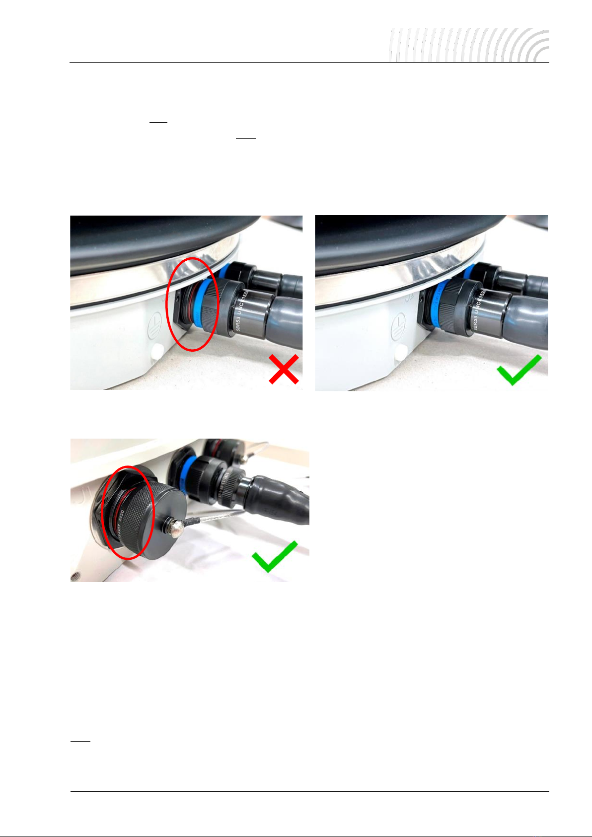
1.3 Watertightness Disclaimer
This product is designed and tested to fulfill ingress protection requirements according to IP 67. Note that
watertightness is only ensured with the cables properly plugged in and screwed or the protective waterproof
caps fitted to all connector ports. Do NOT unscrew the protective bronze cap unless you need to access the
turning knob for powerless top surface movement (see chapter 7.3).
Before use, please double check to make sure the connectors are not tilted or jammed. You should be able to
smoothly screw the connector coupling nut all the way onto the sockets until the red ring is not visible anymore,
as shown below:
With the protective caps instead of the cables fitted to the sockets, the red rings will still be visible:
Please note that SOMAG AG Jena is not liable for water damages caused by improperly connected plugs or
disconnected plugs.
This disclaimer also includes water damages due to damages of the protective bellow caused by the use of
rough physical force or improper handling. Before use, please check the protective bellow for any tears or
cracks.
SOMAG AG Jena reserves the right to perform a cause analysis of devices damaged by water ingress to de-
termine whether the defect is covered by the warranty. In case of damage to the bellow or connector ports, do
NOT expose the Stabilization Mount to water, dust or any other harsh environment to prevent critical damage.
In this case, please contact SOMAG AG Jena for the quickest possible repair to guarantee a long service life.

112304-901-08/03
NSM 400
7 / 26
1.4 Environmental- and Application Conditions
It is necessary to follow the mechanical and electrical mounting advices described in chapter 4.1 and 4.2. The
components need to be installed by staff properly trained and qualified to install the equipment.
In addition, only staff members that are trained to handle the equipment should be allowed to use the NSM
400. Improper handling of the device will void the warranty and shorten the lifetime.
1.5 Risk Analysis
1.5.1 Risks during installation and maintenance
Risks detected
Preventive measures
Fingers getting caught in be-
tween moving parts
Do NOT touch the device by the areas marked by the red crosses as
shown in Figure 2.
Impact by sudden Mount /
payload movement
Maintenance work or installation of the Stabilization Mount / payload
ONLY with the device powered off and the power cable disconnected.
First start-up of the device WITHOUT the payload installed.
1.5.2 Risks during use
Risks detected
Preventive measures
Impact by Mount / payload
movement
With the device powered on, permanently monitor the safety area around
the device or ensure that no person can enter the safety area, as de-
scribed in chapter 1.6
Falling or ejected objects
Regularly check the tightening of the Stabilization Mount and payload fas-
teners.

112304-901-08/03
NSM 400
8 / 26
1.6 Safety Area
A safety area must be delimited around the Stabilization Mount in order to avoid any collision during the sta-
bilization motions. This perimeter must consider the Stabilization Mount’s maximal motions together with the
falling and/or projection risks associated with the payload placed on it. Safety markings, in compliance with
current standards, must forbid access to the safety area during movements. The implementation of this safety
protection is the responsibility of the customer.
Figure 1: Safety Area
1
•The safety area is the minimum area which needs to be secured around the Stabilization
Mount. It is the user’s responsibility to do a risk analysis to define the right area size according
to the circumstances as shown in Figure 1and in accordance with the used payload.
1
Distance between Mount pivot and top mounting plate; compare Figure 5
payload height + 54 mm1+
safety margin (e.g. 100 mm)

112304-901-08/03
NSM 400
9 / 26
1.7 General Safety Tips
•Lift up and carry the NSM 400 as shown in the following illustration. Any other handling can
cause fatal damage. Pick up the device only at the marked areas to avoid any damage (see
Figure 2).
Figure 2: Lifting the NSM 400
•DO NOT lift the NSM 400 by the areas marked by the red crosses. You will likely squeeze your hands if you
use these positions to lift and carry the device. Furthermore, it is possible to damage the shell of the unit.
•The Mount is switched ON as soon as the power supply will be connected. Make sure that the device is
properly secured / bolted to a stable and even surface before power will be applied. It is recommended to
run the Mount for the first trials without any payload.
•Always make sure the payload is properly secured / bolted to the Mount’s top plate and does not exceed
the maximum payload resp. fulfills the conditions shown in chapter 4.1.2 and 4.1.3. The manufacturer is
not responsible for any damages resulting from improperly secured payloads.
•If the power supply is disconnected or not active, the Stabilization Mount will freeze in its current position.
It is not possible to move the payload unless the manual unlocking is activated on purpose (see chapter
7.3).
•During the initialization phase, avoid applying an unnecessary force onto the payload and the Mount, as it
may disrupt the electronic test phase (ETP) and thus reduce stabilization performance. Restarting the
Mount recalibrates the device properly.

112304-901-08/03
NSM 400
10 / 26
2Standard Scope of Delivery
112304-006-02/XX
NSM 400
110088-001-09/XX
110088-100-09/XX
Firmware CPU / Firmware CP1
110002-037-06/XX
Cable Power J1, 5 m, straight
plug, open end
110002-038-06/XX
Cable Interface J2 Basic, 5 m,
straight plug
110002-039-06/XX
Cable Interface J2, 0.3 m,
MAIN/AUX/ETH, straight plug
110002-040-06/XX
Cable Interface J3, 3 m,
straight plug
110003-001-06/XX
USB flash drive with software
SOMAG Mount Control App
112304-901-08/XX
NSM 400 Manual
110080-901-08/XX
SOMAG Mount Control App –
Manual
112300-385-02/XX
Bag with Handling Details and Por-
tage Sensors
112304-400-03/XX
Transportation and Storage Box
1
Software pre-installed on device / not physically available

112304-901-08/03
NSM 400
11 / 26
•You will receive an individual scope of delivery with your order. The content which is shown
above refers to the standard scope of delivery which can vary for each specific order. Please
make sure that the items according to your quote, purchase order and delivery are included in
your package and contact the manufacturer (SOMAG AG Jena) if an item is missing!

112304-901-08/03
NSM 400
12 / 26
3Specifications
The Mount is specifically designed to be placed on marine vessels and floating platforms. A usage in other
vehicles needs to be checked and cannot be verified in general because the performance may vary.
Angular Stabilization Ranges
Pitch - at 0° Roll
Roll - at 0° Pitch
≤ ± 20.0°
≤ ± 20.0°
Yaw (Drift)
no drift correction
Residual Deviation1
≤ 0.4° rms
Payload2
100 kg / 70 kg / 55 kg
Continuous Torque3
125 Nm
Dynamic Peak Torque4
250 Nm
Mass
33 kg
Dimensions (regular leveling positions):
Height
Diameter
290 mm
Ø 486 mm
IP Class
IP 67
Operating Temperature
-30 °C to +55 °C
Storage Temperature
-55 °C to +85 °C
Communication Interfaces
Ethernet / RS422 / RS232
Operational Voltage
28 VDC (24 … 30 VDC)
Average Power Consumption5at Operational Voltage
90 W
Peak Power Consumption5at Operational Voltage
450 W
Applied Standards
IACS E10, DNV GL, 2006/42/EC Machinery
Preliminary data, subject to change
1
Vehicle motion ≤ ±18° / 15°/s / 40°/s² / small periodical lateral accelerations (≤ 0.5 g) acceptable, constant lateral accelerations for
more than 1 minute reduce the performance of the Mount (can be compensated by external GPS input)
2
Possible payload weight depends on lateral acceleration and CoG of payload / shown data is based on 0.9 g lateral acceleration and a
CoG payload offset to the Mount surface of: 250 mm / 400 mm / 500 mm; further information is shown in section 4.1.2
3
See chapter 4.1.3 for continuous torque estimation
4
Maximum duration 90 s at 55 °C surrounding temperature / longer if temperature inside the unit is < 55 °C
5
Horizontal payload CoG offsets are not considered; without wind force and other possible external forces

112304-901-08/03
NSM 400
13 / 26
4Installation
4.1 Mechanical Installation
4.1.1 General Advices
•The device must be installed on a rigid and flat surface (see Figure 4 / flatness ≤ 0.5 mm). DO NOT install
the NSM 400 on an unstable or uneven base. This could result in damage.
•The area around the device must be large enough to suit the installed payload and to ensure an unob-
structed movement of it.
•The usage of an adapter plate between the mounting surface and the NSM 400 must be authorized by
SOMAG AG Jena or qualified personnel. The installation of an unsuitable adapter could lead to heavy vibra-
tions, which would cause serious damage to the device.
•An installation of a rigid and stiff adapter plate is generally preferred because it ensures a secured mount-
ing of the device. This advice applies to the installation of a wedge adapter as well.
•All measurements in the following technical drawings and images are METRIC!
•Modifications to the payload or the mechanical attachment must be carried out by authorized
personnel. SOMAG AG Jena does not take responsibility for any damages to the payload and
to the NSM 400 caused by an inappropriate installation by unauthorized personnel.
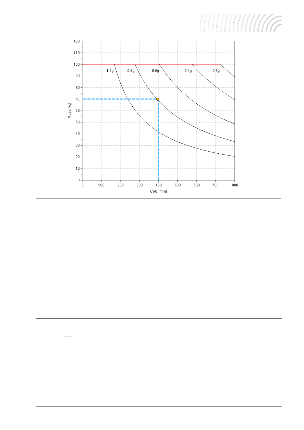
4.1.2 Mass –Center of Gravity –Lateral Acceleration Correlation
•Figure 3 needs to be considered when installing the payload to the NSM 400. Only equipment which fulfills
the graph can be used with the Mount. The shown Center of Gravity (COG) refers to the vertical axis of the
payload. Horizontal offsets are not considered and need to be checked on demand from SOMAG AG Jena
resp. need to be calculated in chapter 4.1.3.
Data example (blue marked): The NSM 400 will work properly with a payload weight of 250 kg, a payload Center
of Gravity of approx. 450 mm above the mounting surface (see Figure 5) and maximum lateral accelerations
(caused by the vessel on which the Mount is installed) of 0.5 g. Any other conditions which fit the diagram will
work as well.
112304-901-08/03
NSM 400
14 / 26
Figure 3: NSM 400 mass –center of gravity –lateral acceleration correlation
4.1.3 Continuous Torque Estimation
The continuous torque, which needs to be smaller or equal to the continuous torque shown in chapter 3, can
be estimated using the following formulas:
Formula
Symb.
Unit
Description
Nm
Torque caused by the payload’s inertia
and vehicle motion
Nm
Torque caused by lateral accelerations
Nm
Torque caused by wind force of the pay-
load
Nm
Torque caused by horizontal CoG offset
of the payload –to be avoided!
kgm2
Payload moment of inertia
kg
Payload point mass
m
Vertical offset between the payload’s cen-
ter of gravity and the stabilization Mount’s
pivot
deg/s2
Angular acceleration

112304-901-08/03
NSM 400
15 / 26
m
Vertical distance between the vehicle’s
pivot and the payload CoG
deg/s2
Angular acceleration
m/s2
Lateral acceleration- x-direction
m/s2
Lateral acceleration- y-direction
m2
Surface area of the payload caught by the
wind
m2
Drag coefficient of the payload (the geo-
metric form may be simplified)
kg/m3
Air density
m/s
Wind speed
m/s2
Gravitational acceleration –9.81 m/s2
m
Horizontal offset between payload CoG
and center of stabilization Mount’s sur-
face –x-direction
m
Horizontal offset between payload CoG
and center of stabilization Mount’s sur-
face –y-direction
•The Mount can only work properly when the continuous torque (Mcont), which is caused by the
payload and its environmental conditions, is smaller than the continuous torque limit of the
Mount shown in chapter 3.
112304-901-08/03
NSM 400
16 / 26
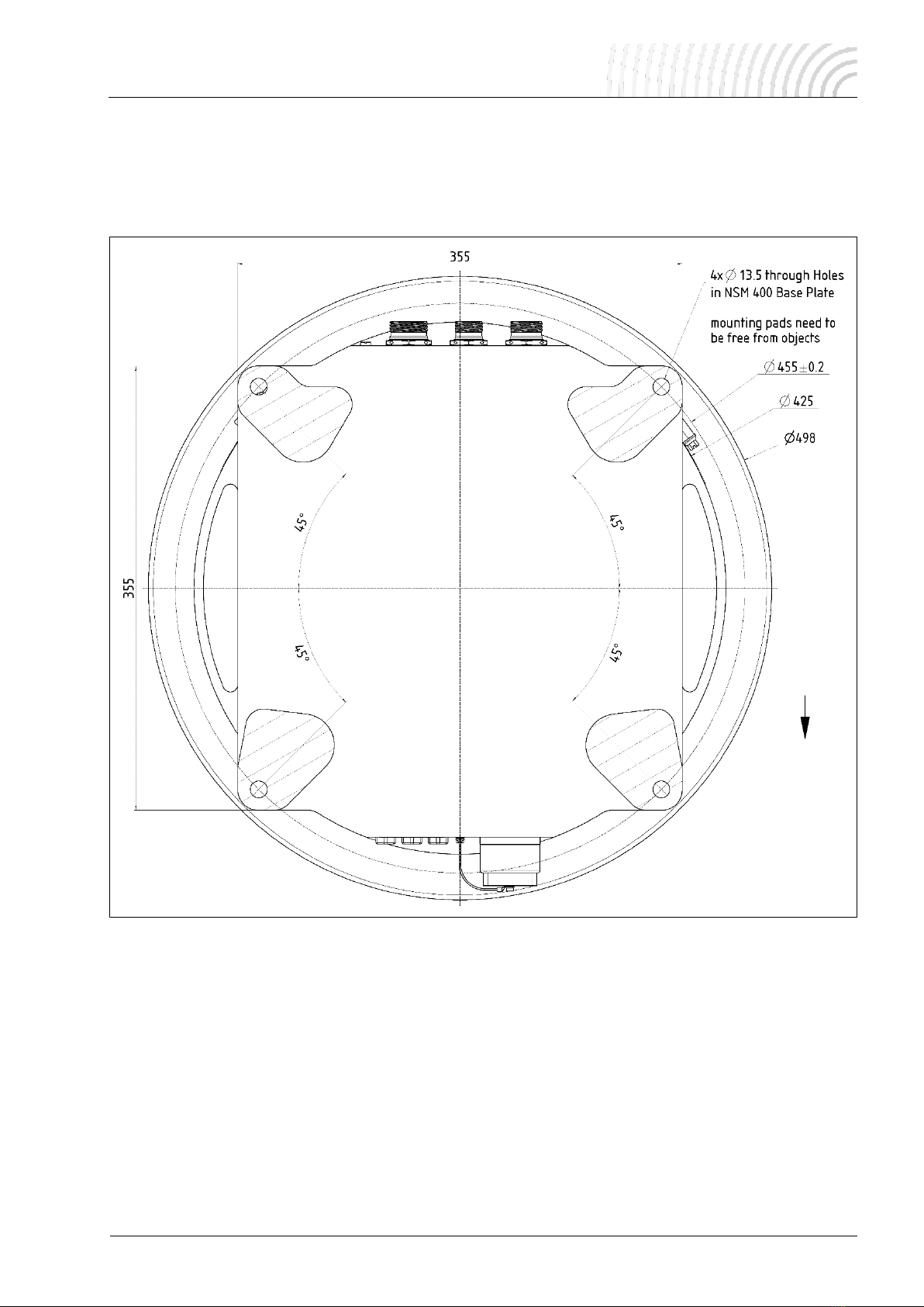
4.1.4 Dimensions of Fastening Holes / Footprint
•4x Ø13.5 mm through holes in the NSM 400 base plate to fasten the device.
•Screws must be longer than 17.5 mm to run through the NSM 400 base plate.
•All Dimensions METRIC!
Figure 4: Dimensions of fastening holes for the NSM 400
4.1.5 Installation / Installing the NSM 400
•Make sure that the mounting pad area (see Figure 4) is clear of objects.
•Position the device straight over the installation holes.
•Install the NSM 400 with four screws. A torque of 30 Nm is required to secure the device safely.
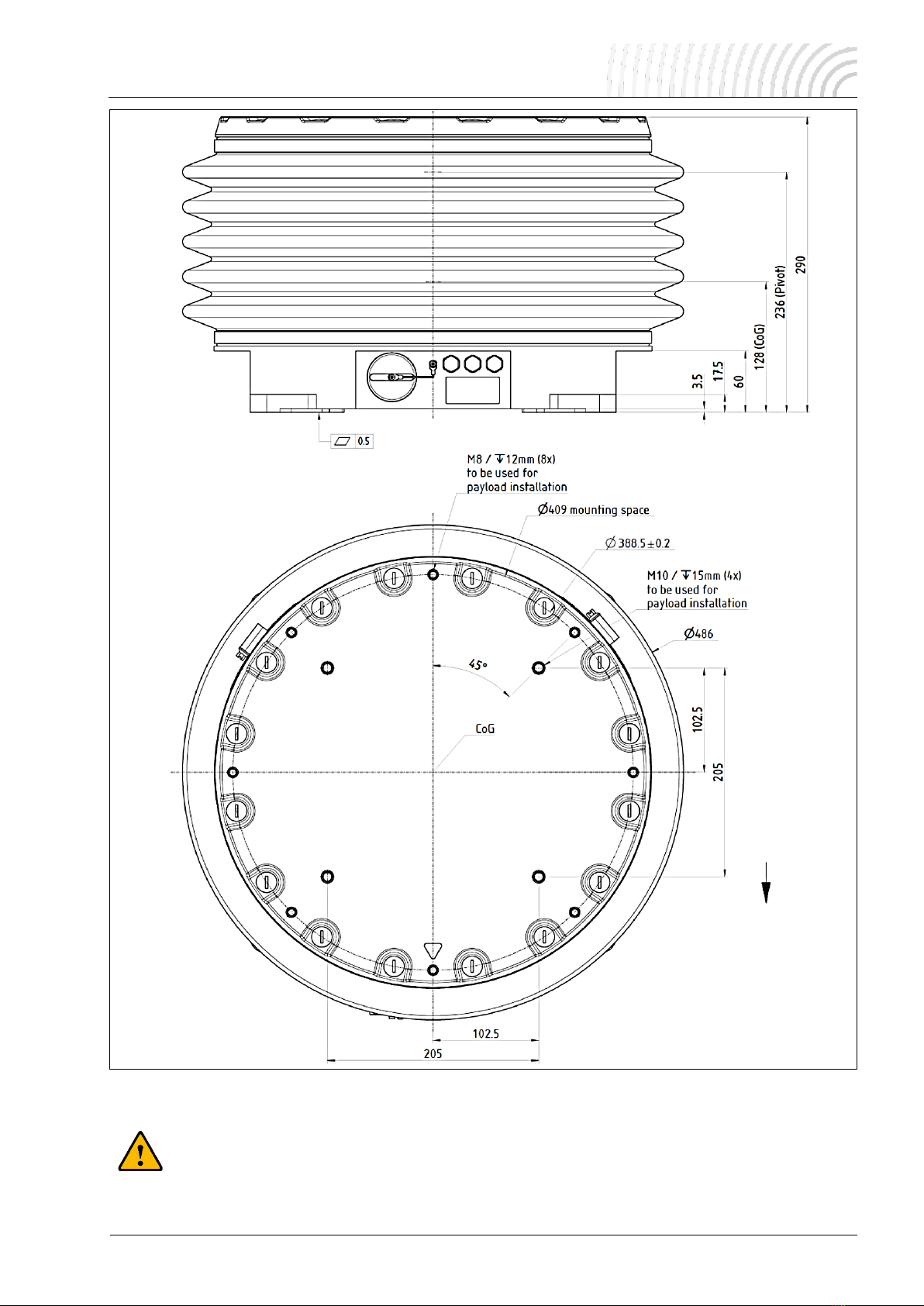
4.1.6 Main Dimensions / Mounting the Payload
Figure 5 illustrates the main dimensions of the device, the payload mounting holes and the pivot. 8x
M8 / 12 mm and 4x M10 / 15 mm deep threaded holes are provided for installation purposes. It is necessary
to use at least 4x mounting holes to install the payload or an adapter plate properly.
Device Orientation
Device Orientation
112304-901-08/03
NSM 400
17 / 26
Figure 5: NSM 400 payload mounting holes, main dimensions, cog and pivot
•It is always desired to move the center of gravity of the payload to the middle of the usable
diameter. This ensures the best dynamic behavior and stabilization performance of the Mount
and avoids an unnecessary increase in power consumption.
Device Orientation
Device Orientation

112304-901-08/03
NSM 400
18 / 26
4.2 Electrical Installation
4.2.1 General Advice
•DO NOT excessively bend the cables of the NSM 400. Allow a minimum bending radius of 80 mm for all
cables.
•Provide strain relief for all connectors to prevent the cables, plugs or sockets from breaking when moved
or bent.
•Avoid unnecessarily long and unfixed cables to prevent fluttering caused by strong winds.
•It is absolutely vital to install all cables or protective caps for connectors J1, J2 and J3 to
ensure waterproofing according to IP 67 class!
4.2.2 Cabling of the NSM 400
Figure 6: Cabling of the NSM 400
A –Grounding
Use the M5 / 6 mm deep threaded hole to ground the NSM 400. Replace the protective nylon screw with a
metal screw!
•This connection must NOT be used for grounding the payload!
Especially with regard to lightning protection, it is the responsibility of the user to attach a ground connection
to the payload.
B –Power-Supply J1 Connector
Connect the power cable J1 here. For connector PIN assignment see chapter 4.2.3.
C –Interface J2 Connector
Use the interface cable J2 basic and the interface cable J2 to link the Mount with a remote computer. For
connector PIN assignment see chapter 4.2.5.
D –Interface J3 Connector
Use the interface cable J3 to link the Mount with an inertial system. For connector-PIN-assignment see chap-
ter 4.2.6.

112304-901-08/03
NSM 400
19 / 26
4.2.3 Power J1 Cable
Wire
Pin
Function
red/brown/1
A/1
+28 VDC
blue/black/2
B/2
0 V
shield
housing
ground
4.2.4 Interface J2 Basic Cable
•The basic interface cable is used to bridge the distance between the Mount and the interface cable J2.
Cable lengths up to 30 m are possible.
Figure 7: Wiring scheme interface J2 cable (left) and interface J2 basic cable (right)
It is recommended to use:
•A safeguard against accidentally reversing the po-
larity.
•An external fuse with a max. current of 32 A.

112304-901-08/03
NSM 400
20 / 26
4.2.5 Interface J2 Cable
MAIN (RS-422)
•to be used for communication via Mount Communication Protocol 2.0.
•connector type: D-Sub 9-way, female, 4-40 UNC thread (see below table for pin assignment).
AUX J2 (RS-422)
•to be used to receive navigation / IMU data (NMEA data).
•connector type: D-Sub 9-way, female, 4-40 UNC thread (see below table for pin assignment).
ETH (Ethernet)
•to be used for communication with Mount Control App or/and
•for communication via Mount Communication Protocol 2.0 or/and
•for receiving NMEA or similar navigation data.
•connector type: RJ-45 / 10BASE-T and 100BASE-TX without POE.
•Data exchange is not possible using Mount Communication Protocol 2.0 simultaneously via
MAIN and ETH.
•Data traffic using Mount Communication Protocol 2.0 via ETH blocks data exchange via
MAIN (1 s delay time after the last ETH traffic).
•Sending data to a remote computer simultaneously via ETH and MAIN is possible only if data
exchange for Mount Communication Protocol 2.0 via ETH is used.
•It is not possible to use Interface J2 AUX and J3 AUX simultaneously. If devices are connected
to both interfaces, J3 has priority.
Connector D-Sub 9-way, fe-
male, 4-40 UNC thread
MAIN (RS-422)
AUX J2 (RS-422)
Pin
Function
Function
1
RxD-
RxD-
2
RxD+
RxD+
3
TxD+
TxD+
4
TxD-
TxD-
5
n.c.1
signal-GND
6 … 9
n.c.1
n.c.1
housing
ground
ground
1
Pins must not be connected.
Table of contents
Other SOMAG Boating Equipment manuals

Popular Boating Equipment manuals by other brands


Prospec Electronics
Prospec Electronics INFPRV350 owner's manual

Quick
Quick AL3 ALEPH Series Installation and user manual

Taylor Made
Taylor Made Pontoon Quick-Shade Gazebo instructions

Taylor Made
Taylor Made Convertable Binimi Top Assembly and Instruction Guide

ROCNA
ROCNA Rocna user guide

SEASENS
SEASENS Float Switch installation manual