SOMFY ROLLIXO RTS User manual
ROLLIXO RTS
3 421
Prog
STOP
Installation manual
Instrukcja montażu
Manual de instalación
Εγχειρίδιο εγκατάστασης
EN
PL
ES
EL


Copyright © 2014 SOMFYACTIVITES SA.All rights reserved.
1
EN
Rollixo RTS
CONTENTS
Translated version of the guide 1 - SAFETY INSTRUCTIONS
1.1 Introduction to symbols
This symbol indicates a danger, the different
degrees of which are described below.
DANGER
Indicates a danger which may result in immediate death
or serious injury
WARNING
Indicates a danger which may result in death or serious
injury
PRECAUTION
Indicates a danger which may result in minor or moderate
injury ATTENTION
Indicates a danger which may result in damage to or
destruction of the product
1.2 Introduction
> Important information
Thisproductisareceiverforverticallyopeningrollergarage
doors for residential use. To ensure compliance with the
standard EN 60335-2-95, this product must be installed
with a Somfy RDO CSI motor and a Somfy safety edge
solution. The assembly is together designated as a "drive".
This drive is exclusively intended to equip a garage door
designed for residential use.
The main purpose of these instructions is to satisfy the
requirementsoftheaforementionedstandardandtoensure
the safety of equipment and persons.
WARNING
$Q\ XVH RI WKLV SURGXFW RXWVLGH WKH ¿HOG RI DSSOLFDWLRQ
described in this manual is prohibited (see "Field of
application" paragraph in the installation manual).
The use of any accessory or any component not
recommended by Somfy is prohibited, on safety grounds.
Somfycannotbeheldliableforanydamageresultingfrom
failure to follow the instructions in this
manual.
In case of any doubts when installing the drive, or to obtain
additionalinformation,consultthewebsitewww.somfy.com.
7KHLQVWUXFWLRQVPD\EHPRGL¿HGLIDQGZKHQWKHUHLVD
change to the standards or to the drive.
1 - Safety instructions______________________________ 1
1.1 Introduction to symbols 1
1.2 Introduction 1
1.3 Caution - Important safety instructions 2
1.4 Preliminary checks 2
1.5 Electrical pre-equipment 2
1.6 Safety instructions relating to installation 2
1.7 Regulations 3
1.8Assistance 3
1.9 Risk prevention 3
2 - Description of the Rollixo receiver_________________ 4
2.1Area of application 4
2.2 Description of the receiver 4
2.3 Description of the external programming interface 4
2.4 Space requirements 4
2.5 Standard installation diagram 4
3 - Installation ____________________________________ 5
3.1 Mounting the Rollixo receiver 5
3.2 Motor and fall protection wiring 5
3.3 Connecting the receiver to the mains power supply 5
3.4 Checking the direction of rotation of the motor and adjustment of the
motor end limits 6
4 - Installing an optical radio safety edge or resistive safety
edge with XSE transmitter________________________ 6
4.1 Installing the optical radio or resistive safety edge and its XSE
transmitter 6
4.2 Installing a base magnet on the door runner 6
4.3 Programming the XSE transmitter 7
4.4 Recognition of the lower magnet 7
5 - Checking operation of the receiver ________________ 7
5.1 Operation in sequential mode 7
5.2 Integrated lighting 7
5.3 Orange light 7
5.4 Cells 7
5.5 Safety edge 7
5.6Alarm (optional) 7
6 - User training___________________________________ 8
7 - Connecting additional devices____________________ 8
7.1 General wiring diagram 8
7.2 Parameter setting for wiring options 8
7.3 Description of the various additional devices 8
8 -Advanced parameter setting_____________________ 10
8.1 Different operating modes 10
8.2 Programming operating modes 10
8.3 Holiday mode 11
9 - Storing the remote controls _____________________ 11
9.1 Memorising 2 or 4-button remote controls 11
9.2 Memorising 3-button remote controls 11
9.3 Memorising by copying a previously memorised remote control 11
10 - Memorising an XSE safety edge transmitter_______ 12
11 - Clearing the remote controls____________________ 12
11.1 Clearing a remote control 12
11.2 Clearing all remote controls 12
12 - Deleting a safety edge transmitter _______________ 12
13 - Locking/unlocking the programming buttons______ 12
14 - Diagnostics__________________________________ 12
14.1 Receiver 12
14.2 XSE transmitter 14
15 - Technical data________________________________ 14

2
Copyright © 2014 SOMFYACTIVITES SA.All rights reserved.
EN
Rollixo RTS
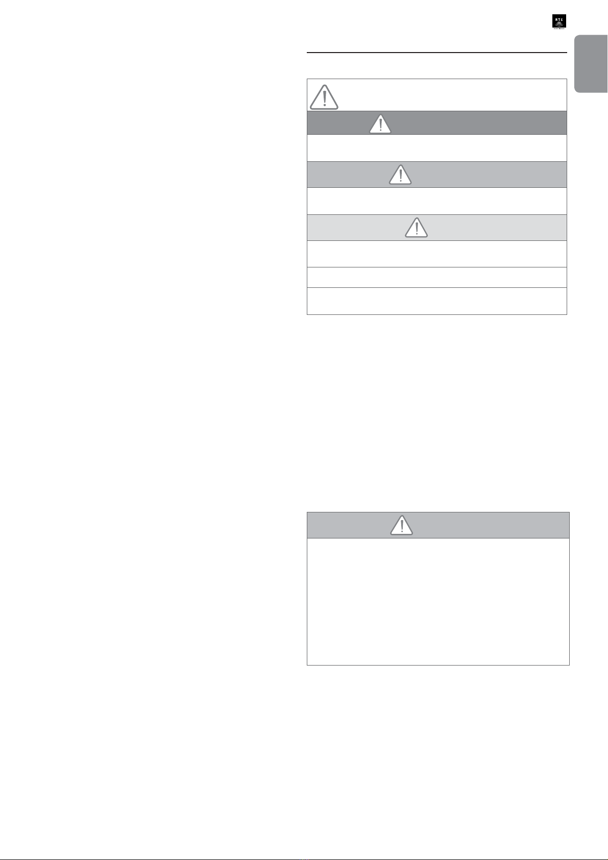
1.3 Caution - Important safety instructions
DANGER
Thedrivemust be installed andadjustedby a professional
motorisationandhomeautomationinstaller, incompliance
withthe regulations ofthecountry in whichitis to beused.
Failure to follow these instructions may result in serious
injury, e.g. due to crushing by the gate.
WARNING
Caution - Important safety instructions
For reasons of personal safety, it is important to follow
all the instructions, as incorrect installation can lead to
serious injury. Retain these instructions.
Theinstallermusttrainalluserstoensurethedriveisused
in complete safety, in accordance with the user manual.
The user manual and installation manual must be given
to the end user. The installer must explain clearly to the
end user that installation, adjustment and maintenance of
the drive must be performed by a professional drive and
home automation installer.
1.4 Preliminary checks
> Installation environment
ATTENTION
Do not spray water onto the drive.
Do not install the drive in an explosive environment.
Check that the temperature range marked on the drive is
suited to the installation location.
> Condition of the door to be motorised
See the safety instructions for the RDO CSI motor.
1.5 Electrical pre-equipment
DANGER
The installation of the power supply must comply with
the standards in force in the country in which the drive is
LQVWDOOHGDQGPXVWEHFDUULHGRXWE\TXDOL¿HGSHUVRQQHO
The electric line must be exclusively reserved for the drive
and equipped with protection, comprising:
- a 10Afuse or breaker,
- a differential type device (30 mA).
An all-pole power supply cut-off device must be provided.
,W LV UHFRPPHQGHG WKDW \RX ¿W D OLJKWQLQJ FRQGXFWRU
(maximum residual voltage 2 kV).
> Cable feed
Underground cables must be equipped with a protective
VKHDWKZLWKDVXI¿FLHQWGLDPHWHUWRFRQWDLQWKHPRWRUFDEOH
and the accessories cables.
For overground cables, use a cable grommet that will
withstand the weight of vehicles (ref. 2400484).
1.6 Safety instructions relating to installation
DANGER
Do not connect the drive to a power source before
installation is complete.
WARNING
Ensurethatany danger zones (crushing,cutting,trapping)
EHWZHHQWKHGULYHQSDUWDQGWKHVXUURXQGLQJ¿[HGHOHPHQWV
caused by the opening movement of the driven part are
avoided or indicated on the installation (seethe section on
risk prevention).
WARNING
Modifying one of the elements provided in this kit or using
an additional element not recommended in this manual is
strictly prohibited.
Monitor the door as it moves and keep people away from it
until installation is complete.
Do not use adhesive to secure the drive.
ATTENTION
,QVWDOODQ\¿[HGFRQWUROGHYLFHDWDKHLJKWRIOHVVWKDQ
mandwithinsightofthedoor,butawayfrommovingparts.
After installation, ensure that:
- the mechanism is correctly adjusted
- thedrivechangesdirectionwhenthedoorencountersan
object 50 mm high on the ground.
WARNING
CAUTION: Automatic door – The door may operate
unexpectedly. Do not leave anything in the door's path.
> Safety devices
DANGER
A fall protection device suited to the weight of the door
must be installed to prevent the risk of the door falling.
WARNING
For operation in automatic mode or remote control,
photoelectric cells must be installed.
The automatic drive operates in at least one direction with
no intentional activation by the user.
WARNING
For operation by pressing and holding down the button
following a fault with the safety device, the door must be
operated within sight of the door.
Copyright © 2014 SOMFYACTIVITES SA.All rights reserved.
3
EN
Rollixo RTS
Foroperationinautomaticmode,orifthegaragedoorfaces
apublicroad,anorangelighttypesignallingdevice may be
required to comply with the regulations in the country in
which the drive is installed.
> Clothing precautions
Take off any jewellery (bracelet, chain, etc.) during
installation.
For manoeuvring, drilling and welding operations, wear
appropriate protection ( special glasses, gloves, ear
protection, etc.).
1.7 Regulations
Somfy declares that the product described in these
instructions,whenusedinaccordancewiththeinstructions,
complies with the essential requirements of the applicable
European Directives, and in particular Machinery Directive
2006/42/EC and Radio Equipment Directive 2014/53/EU.
The full text of the EC declaration of conformity is available
on the following website: www.somfy.com/ce. Antoine
CREZE, Head of Regulations, Cluses.
1.8 Assistance
<RX PD\ HQFRXQWHU GLI¿FXOWLHV RU KDYH TXHVWLRQV ZKHQ
installing your drive.
Donothesitatetocontactus;ourspecialists are on hand to
answer all your questions.
Internet:www.somfy.com
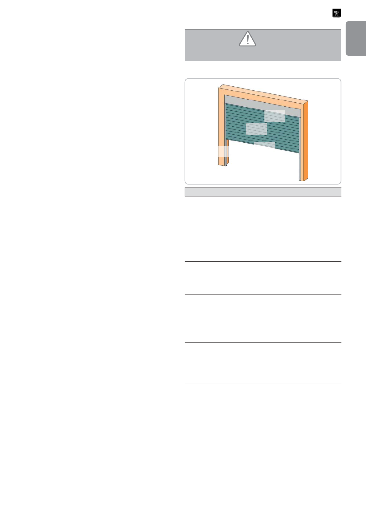
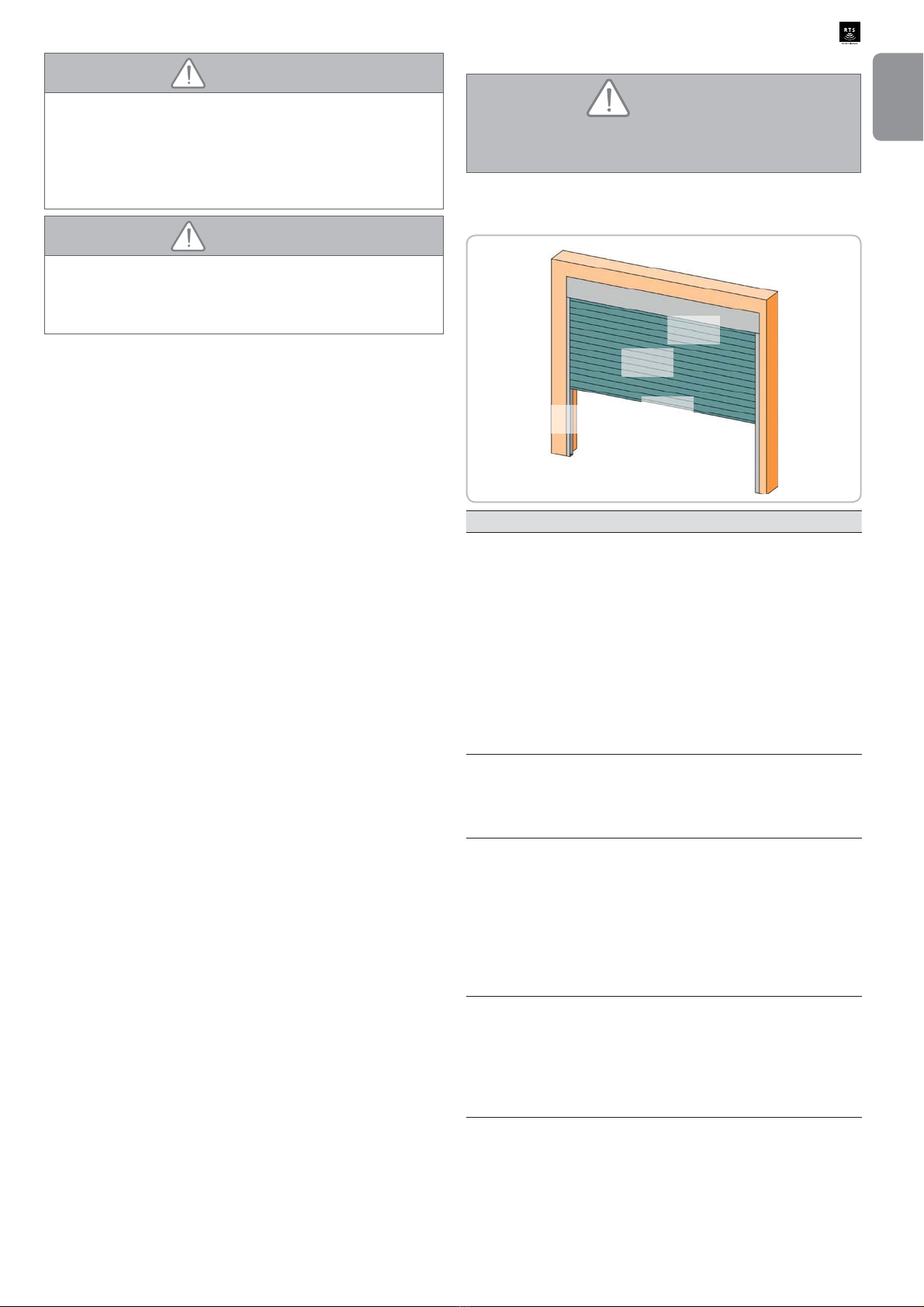
1.9 Risk prevention
WARNING
Risk prevention - roller garage door drive for
residential use
> Risk zones: measures to be taken to eliminate risks.
Zone 1
Zone 2
Zone 3
Zone 4
RISK SOLUTION
ZONE 1
Risk of crushing
between the ground
and the lower edge of
the door during closing
Obstacle detection by the
safety edge solution Obstacle
GHWHFWLRQ PXVW EH FRQ¿UPHG
as compliant with Appendix A
of standard EN 12 453
For operation with automatic
closing, install photoelectric
cells (see installation manual)
ZONE 2*
Risk of crushing
between the casing
and door
(OLPLQDWHDQ\JDSPPRU
PPEHWZHHQWKHFDVLQJ
and door
ZONE 3*
Risk of cutting or
trapping between the
door slats in gaps of
between 8 mm and 25
mm
Eliminate all sticking points
and all sharp edges from the
surface of the door
(OLPLQDWHDQ\JDSPPRU
PP
ZONE 4*
Risk of crushing
between the runners
and door
Eliminate any sharp edges
from the runners
(OLPLQDWH DQ\ JDS PP
between the runners and the
door
* For zones 2, 3 and 4, no protection is required if the door
has continuous control or if the danger zone is more than
2.5 m above ground or any other permanent access level.

4
Copyright © 2014 SOMFYACTIVITES SA.All rights reserved.
EN
Rollixo RTS
2 - DESCRIPTION OF THE ROLLIXO
RECEIVER
2.1 Area of application
The ROLLIXO receiver, linked to a Somfy RDO CSI motor and a Somfy safety
edge solution, is designed to drive a vertically opening roller garage door for
residential use with the following external dimensions:
- Height = 4 m maximum
- Width = 6 m maximum
2.2 Description of the receiver
34
2
1
Prog
STOP
1
2
3
4
5
6
7
8
11
9
13
12
10
14
No. Description
1 Integrated lighting bulb
2 Receiver cover
3 Receiver cover bolt
4 External programming interface
5 Internal programming interface
6 433.42 MHz aerial
7 Plug-in terminals
8 Cable clamp
9 Cable clamp bolt
10 Alarm bolt
11 Fall protection shunt
12 Safety fuse for motor and integrated lighting
13 Spare fuse
14 E14 - 1.4W - 230V LED bulb
2.3 Description of the external programming interface
3 421
Prog
STOP
1
2
3
678 9
5
4
No. Description Function
1 Up button Opening the door
2 STOPButton Stopping the door
3 Down button Closing the door
4 Prog Button Programming radio transmitters
5 Prog Indicator light Information on radio reception and
programming radio transmitters
6 Motor and fall
protection warning light Information on the status of the motor and
fall protection
7 Safety edge indicator
light Information on the status of the safety
edge and the safety edge transmitter
8 Battery indicator light Information on the status of the battery
and the safety edge transmitter
9 Cell indicator light Information on the status of the cells
2.4 Space requirements
60,6 157,7
182,7
261,9
2.5 Standard installation diagram
Motor Receiver
Safety edge
Safety edge
transmitter
Fall protection

Copyright © 2014 SOMFYACTIVITES SA.All rights reserved.
5
EN
Rollixo RTS 3 - INSTALLATION
3.1 Mounting the Rollixo receiver
Ensure a suitable distance from the wall socket (2 m power supply
cable supplied).
It is advisable to install the receiver on the same side of the door as
the safety edge transmitter.
[1]. Remove the integrated light bulb.
[2]. Unscrew and remove the receiver cover.
[3]. Mark the drill holes.
[4]. Mount the receiver onto the wall.
[1] [2]
[3] [4]
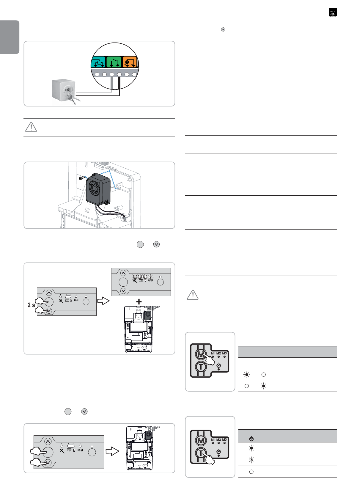
3.2 Motor and fall protection wiring
The receiver must not be connected to the mains power supply
during connection to the motor.
> Motor wiring
[1]. Connect the motor to the receiver.
Note: the motor'sdirection of rotationshall then bechecked andreversed
if necessary.
L1 L2N
M
1234
Vert/jaune
Bleu
Marron
Noir
[2]. Lock the motor cable with the cable clamp provided.
The motor cable must be placed in the receiver's 230 V insulation
area.
230V insulation zone 24V insulation zone
> Fall protection wiring
The fall protection device must be wired.
Sec
Safety EdgeStop
K
56 7 8 9 1
3.3 Connecting the receiver to the mains power supply
[1]. Fully unfold the receiver aerial so that it is pointing downwards.
[2]. Screw the bulb supplied into the receiver.
WARNING
An LED bulb of the same type as that supplied (E14 - 1.4W - 230V) must be
used. Using another type of bulb may cause high dangerous overheating.
[3]. Replace and screw in the receiver cover.
[4]. 5H¿WWKHLQWHJUDWHGOLJKWLQJEXOE
[5]. Connect the receiver to the mains power supply .
All the indicator lights come on and then go out.
Ifindicatorlight1 comesonpermanently,fallprotectionisnotconnected
or incorrectly connected to the receiver.
Ifindicatorlight2 comesonpermanently,thesafetyedgehas notbeen
detected by the receiver (radio safety edge transmitter not yet memorised
or the wired safety edge is still not connected).
3 421
Prog
STOP
[1] [2]
[3] [4]
[5]

6
Copyright © 2014 SOMFYACTIVITES SA.All rights reserved.
EN
Rollixo RTS
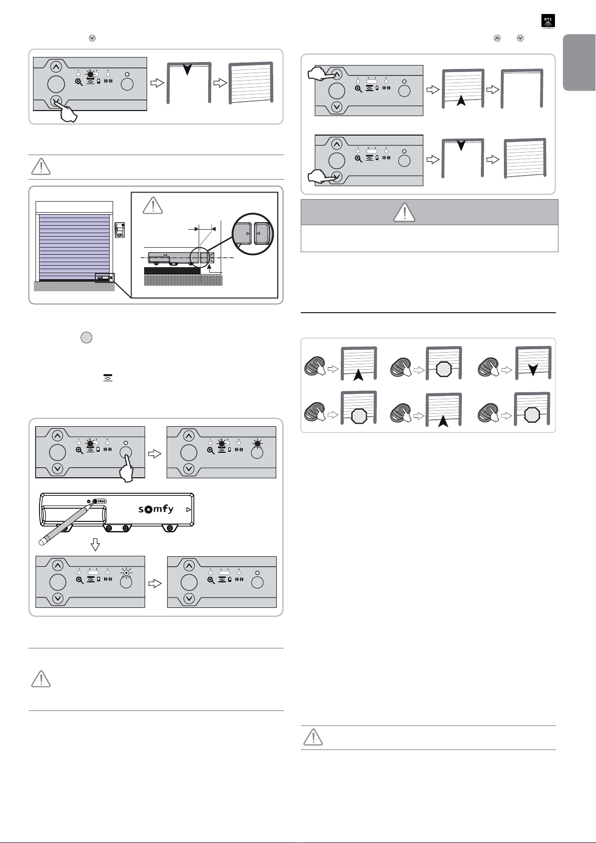
3.4 Checking the direction of rotation of the motor and
adjustment of the motor end limits
[1]. Press simultaneously on the and buttons until the motor's up and
down movement occurs to enter motor adjustment mode.
Indicator light 1 ÀDVKHVVORZO\
3 421
Prog
STOP
[2]. Press button or to check the motor's direction of rotation.
- If the motor's direction of rotation is correct, move on to step [3] of the
motor end limit setting procedure.
- If the direction of rotation is incorrect, press button STOP until the motor's
up and down movement occurs, check the motor's direction of rotation
again and move on to step [3] of the motor end limit setting procedure.
Step [3]
3 421
Prog
STOP
3 421
Prog
STOP
Correct direction of
rotation Incorrect direction
of rotation
[3]. If the motor end limits are already set, move on to step [8] to exit motor
adjustment mode.
If the motor end limits are not set, check that the motor is released: the
two push-buttons should be pressed.
Note: The motor end limits can also be set with a setting cable (ref.
9015971). In this case, set the motor end limits with the cable then
move on to step [8] to exit motor adjustment mode.
[4]. Press button to position the garage door in the upper position.
Adjust the top position using buttons and .
3 421
Prog
STOP
[5]. Press the motor's upper end limit push-button.
or
[6]. Press button to position the garage door in the low position.
Adjust the bottom position using buttons and .
3 421
Prog
STOP
[7]. Press the motor's low end limit push-button.
or
[8]. Press simultaneously on the and buttons or press the Prog button
until the motor's up and down movement occurs to exit motor adjustment
mode.
Indicator light 1 goes out.
3 421
Prog
STOP
3 421
Prog
STOP
or
4 - INSTALLING AN OPTICAL RADIO
SAFETY EDGE OR RESISTIVE SAFETY
EDGE WITH XSE TRANSMITTER
4.1 Installing the optical radio or resistive safety edge
and its XSE transmitter
Follow the instructions provided with the XSE transmitter and the optical or
resistive safety edge installation kit.
4.2 Installing a base magnet on the door runner
$EDVHPDJQHWPXVWEH¿WWHGIRUDUHVLVWLYHVDIHW\HGJH
This is VWURQJO\ UHFRPPHQGHG for an optical safety edge. The
presence of a bottom magnet makes it possible to:
- extend the battery life
- eliminate the risk of ground detection, to secure the closing of the
door
- automatically activate the maximum level of sensitivity of the
movement sensor
- increase the sensor operating time by 25 to 35 seconds when the
base magnet is detected.
Copyright © 2014 SOMFYACTIVITES SA.All rights reserved.
7
EN
Rollixo RTS
[1]. Press button to position the garage door in the low position.
3 421
Prog
STOP
[2]. Attach the magnet to the edge of the runner, positioning it in line with the
transmitter.
This operation is important. Ensure the dimensions are observed.
10 mm maxi.
Lower
magnet
4.3 Programming the XSE transmitter
[1]. Press the Prog button on the receiver until the indicator light comes on
permanently.
[2]. Using the tip of a pen, press the transmitter PROG push-button for 4
seconds.
Indicator light 2 on the receiver goes out and the receiver Prog
LQGLFDWRUOLJKWZLOOÀDVKDQGWKHQJRRXWWKLVPD\WDNHDIHZVHFRQGVZKLOH
the transmitter and receiver communicate with each other).
The transmitter is memorised in the receiver.
3 421
Prog
STOP
3 421
Prog
STOP
3 421
Prog
STOP
3 421
Prog
STOP
4 s
4.4 Recognition of the lower magnet
It is essential that the following procedure is observed to ensure
completely safe operation of the door.
The door must be in the intermediate position before the lower
magnet recognition procedure can be started.
Do not press the safety edge during the lower magnet recognition
procedure.
Run a complete cycle (opening then closing) using buttons and .
3 421
Prog
STOP
3 421
Prog
STOP
WARNING
At the end of installation, it must be checked that the limitation of forces
complies with appendixAof the standard EN 12 453.
5 - CHECKING OPERATION OF THE
RECEIVER
5.1 Operation in sequential mode
STOP
STOP
STOP
5.2 Integrated lighting
The lamp comes on each time a command is sent to the receiver.
It goes out 2 minutes after the door stops.
5.3 Orange light
7KHRUDQJHOLJKWÀDVKHVHYHU\WLPHWKHUHFHLYHULVFRQWUROOHGZLWKRUZLWKRXWD
VHFRQGZDUQLQJGHSHQGLQJRQWKHFRQ¿JXUHGSDUDPHWHUVHWWLQJ
,WVWRSVÀDVKLQJZKHQWKHGRRUVWRSV
5.4 Cells
If the cells are blocked when the door is closed, it stops, then re-opens fully.
If the cells are blocked when the door is opened, the door continues its
movement.
5.5 Safety edge
If the safety edge is activated when the door is closing, it stops then re-opens
partially.
If the safety edge is activated while the door is opening, it continues its
movement.
5.6 Alarm (optional)
The alarm is triggered for 2 minutes if the door is fully closed and raised
manually. No movement of the door is possible when the alarm is sounding.
When the alarm sounds, press a button on a remote control memorised in the
receiver to stop it.
The alarm can only be stopped with a memorised remote control.
8
Copyright © 2014 SOMFYACTIVITES SA.All rights reserved.
EN
Rollixo RTS 6 - USER TRAINING
Train all uses in how to safely use this motorised door (standard use and
locking principle) and on the mandatory periodic checks.
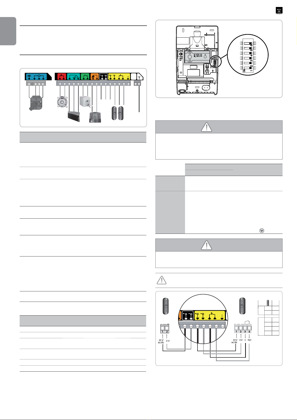
7 - CONNECTINGADDITIONAL DEVICES
7.1 General wiring diagram
L1 L2N
M
1234
24 Vdc
Antenne
R
24V dc 24V Cell
Ant
Sec Cell
Sec
Safety EdgeStop
KeySwitch
Test
Sec
Flash
56 7 8 9 1011 1213 16171819 20 2214 15
Aerial
24 Vdc
Terminal Type of
terminal Connection Comments
1 Earth RDO CSI 50 or 60
motor
2L1
3 Neutral
4L2
5 Contact Fall protection - NC
contact
6 Shared
7 Contact Safety edge safety
input Wired 8k2 resistive safety
edge (terminals 7 - 8)
Wired optical safety edge
(terminals 7 - 8 - 9)
8 12 Vdc 12 Vdc safety edge
power supply
90Vdc
10 Contact NO contact Sequential control
11 Shared
12 24 Vdc 24V - 3.5 W orange
light output Maximum 4 W bulb
13 0 Vdc
14 24 Vdc TX cell 24 V power
supply Transmitting photoelectric
FHOO5HÀH[SKRWRFHOO
power supply
15 0 Vdc
16 24 Vdc RX cell 24 V power
supply Receiving photoelectric
cell power supply
17 0 Vdc
18 Shared
19 Contact Cell safety input (NC)
20 Test output Cell safety test output 5HÀH[SKRWRFHOOVHOIWHVW
22 433.42 MHz aerial Do not connect an offset
aerial (incompatible)
7.2 Parameter setting for wiring options
Dipswitch Possible parameter
setting ON OFF
1 Cell self-test Activated Deactivated
2 Choice of cell type Photoelectric Electric eye
3 Orange light 2s
warning Activated Deactivated
4 Choice of wired safety
edge type Resistive Optical
5 Holiday mode parameter setting (see section 8.4)
6 Do not use
3 421
Prog
STOP
7.3 Description of the various additional devices
> Photoelectric cells
WARNING
N.B.: In accordance with standard EN 12453 governing the safe use
of motorised gates and doors, the use of the TAHOMA control box to
automatically control a garage door or gate not visible to the user requires
the installation of a photoelectric cell type safety device with autotest on the
automatic control system.
Receiver Comments
Dipswitch 1 Dipswitch 2
Without auto-
test OFF ON Requires checking for
correct operation every 6
months.
With auto-test ON ON Enables an automatic
test to be carried out to
check the operation of the
photoelectric cells each time
the door moves.
If the operational test is
negative, closure is in
downgraded mode (press
and hold down ).
WARNING
It is compulsory to install photoelectric cells if:
-the automatic control device isbeing controlled remotely (user unableto see it),
- automatic closure is activated.
If cells are removed, it is essential to create a bridge between
terminals 18 and 19.
1
2
14
15
17
TX
RX
1
2
318
16
519
TX RX
24V dc 24V Cell Sec Cell
Test
Sec
h
16 17 18 19 2014 15

Copyright © 2014 SOMFYACTIVITES SA.All rights reserved.
9
EN
Rollixo RTS
> Reflex photocell
WARNING
N.B.: In accordance with standard EN 12453 governing the safe use
of motorised gates and doors, the use of the TAHOMA control box to
automatically control a garage door or gate not visible to the user requires
the installation of a photoelectric cell type safety device with autotest on the
automatic control system.
Receiver Comments
Dipswitch 1 Dipswitch 2
Without auto-
test OFF OFF Requires checking for
correct operation every 6
months.
With auto-test ON OFF Enables an automatic
test to be carried out to
check the operation of the
photoelectric cells each time
the door moves.
If the operational test is
negative, closure is in
downgraded mode (press
and hold down ).
WARNING
It is compulsory to install photoelectric cells if:
- the automatic control device is being controlled remotely (user unable to
see it),
- automatic closure is activated.
If cells are removed, it is essential to create a bridge between
terminals 18 and 19.
Brown
Blue
14
15
Black
Grey
18
19
24V dc 24V Cell Sec Cell
Test
Sec
h
16 17 18 19 2014 15
ref. 1841195 Note: the white wire must
not be connected.
Brown
Blue
Black
Grey
1
2
14
15
3
4
20
19
518
24V dc 24V Cell Sec Cell
Test
Sec
h
16 17 18 19 2014 15
Ref. 9013647 Cell
Dipswitch 1 Dipswitch 2
Without auto-
test ON ON
With auto-test ON ON
> Optical wired safety edge - Dipswitch 4 receiver set at OFF
Dipswitch 4 receiver position
Sec
Safety EdgeStop
KeySwitch
56 7 8 9 1011 1
Brown
Brown
Brown
White
White
White
Green
Green
Green
If a wired safety edge replaces a radio safety edge, the radio safety
edge transmitter must be cleared (see section 12) to ensure the
wired safety edge is taken into account.
> Wired 8k2 resistive safety edge - Dipswitch 8k2 4 receiver set
to ON
Sec
Safety EdgeStop
KeySwitch
56 7 8 9 1011 1
Dipswitch 4 receiver position
If a wired safety edge replaces a radio safety edge, the radio safety
edge transmitter must be cleared (see section 12) to ensure the
wired safety edge is taken into account.
> Orange LED light (ref. 9017842)
'LSVZLWFKUHFHLYHUVHWWR21ĺVHFRQGZDUQLQJDFWLYDWHG
'LSVZLWFKUHFHLYHUVHWWR2))ĺ1RZDUQLQJ
24V dc 24V C
ge
KeySwitch
Flash
91011 1213 161714 15
4 W max.
10
Copyright © 2014 SOMFYACTIVITES SA.All rights reserved.
EN
Rollixo RTS
> Key lock
Successive presses cause the motor to move (initial position: door closed) as
per the following cycle: open, stop, close, stop, open, etc.
ec
fety Edge
KeySwitch
Flash
8 9 10 11 12 13 1
>Alarm
It is essential to have programmed at least one remote control. The
alarm can only be stopped with a memorised remote control.
• Installing and connecting the alarm
Mount the alarm to the receiver with the bolt provided.
Connect the alarm connector.
• Activating/Deactivating the alarm
To activate/deactivate the alarm, simultaneously press the STOP and buttons
RQWKHUHFHLYHUXQWLOWKHLQGLFDWRUOLJKWVÀDVKUDSLGO\
The alarm emits a beep if it has been activated.
3 421
Prog
STOP
3 421
Prog
STOP
• Alarm operation
The alarm is triggered for 2 minutes if the door is raised manually.
No movement of the door is possible when the alarm is sounding.
When the alarm sounds, press a button on a remote control memorised in the
receiver to stop it. The alarm can only be stopped with a memorised remote
control.
• Alarm operation test
%ULHÀ\SUHVVEXWWRQV STOP and on the receiver simultaneously.
7KHDODUPWULJJHUVEULHÀ\WRLQGLFDWHWKDWLWLVDFWLYDWHG
3 421
Prog
STOP
• Anti-intrusion function test
[1]. Press button to position the garage door in the low position.
[2]. Wait until the transmitter switches to sleep mode (instant if base magnet
installed).
[3]. Manually raise the door by pressing on the rubber.
The alarm is triggered.
[4]. Press a button on a remote control memorised in the receiver to stop the
alarm.
• Optional: lower magnet
$EDVHPDJQHWFDQEH¿WWHGLIWKHDODUPLVWULJJHUHGXQH[SHFWHGO\VHHVHFWLRQ
4.2).
8 - ADVANCED PARAMETER SETTING
8.1 Different operating modes
> 2 operating modes are available:
Sequential (default
mode) Each press on the remote control causes the motor to
move (initial position: door closed) as per the following
cycle: open, stop, close, stop, open, etc.
Semi-automatic In semi-automatic mode:
- pressing a button on the remote control during
opening has no effect,
- pressinga button on the remote control during closing
causes it to reopen.
> 2 automatic closure options are available for the door:
Closure time
delay With automatic closure time delay:
- lthe door is closed automatically after the programmed
time delay has elapsed (20 s, by default),
- pressing a button on the remote control interrupts the
movement taking place and the closure time delay (the
door remains open).
Cell locking Afterthe dooris opened,movementin frontofthe cells(safe
FORVXUHZLOOFORVHWKHGRRUDIWHUDVKRUWWLPHGGHOD\¿[HG
at 5 seconds).
If there is no movement in front of the cells, the door will
closeautomaticallyafter theprogrammedclosuretime delay
(20 s, by default).
If there is an obstacle in the cells' detection zone, the door
will not close. It will close once the obstacle is removed.
Note: by default, no automatic closure option for the door is activated.
The installation of photoelectric cells is mandatory in the event that
an automatic closure option is activated.
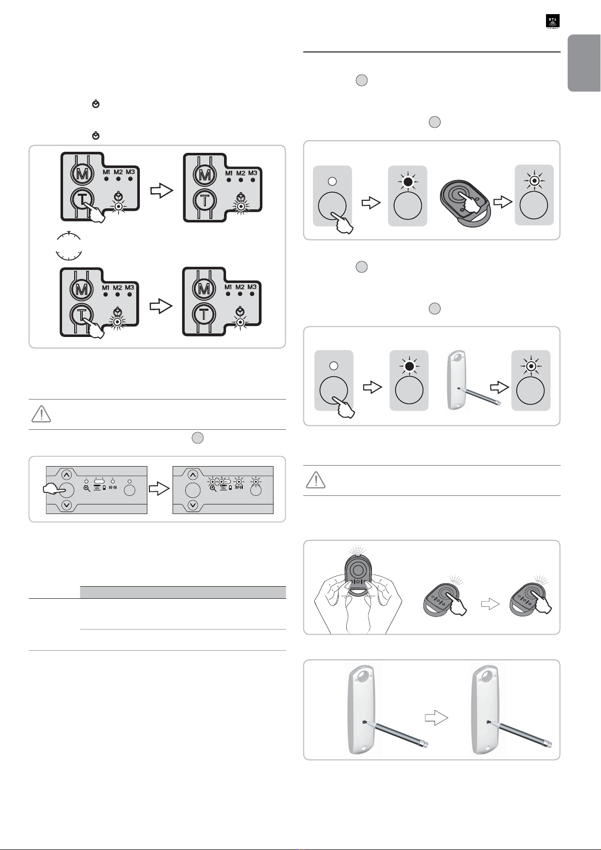
8.2 Programming operating modes
> Changing the operating mode
%ULHÀ\SUHVVWKH0EXWWRQWRVZLWFKIURPVHTXHQWLDO
mode to semi-automatic mode.
Indicator lights Mode activated
M1 M2 M3
Not used
Sequential
Semi-automatic
Automatic closing mode
> Activating/deactivating automatic closing
Short press on the T button to activate automatic
closure.
Indicator
light Automatic closure option
activated
Closure time delay
Cell locking
No option active
Copyright © 2014 SOMFYACTIVITES SA.All rights reserved.
11
EN
Rollixo RTS
> Modification of the automatic closure time delay
Theautomatic closure time delaycan be adjusted from 5 seconds to 2 minutes
(20 seconds by default)
To modify the automatic closure time delay, one or other of the automatic
closure options must be activated.
[1]. Run the timer by pressing and holding down the T button for 2 seconds.
Indicator light ÀDVKHVUDSLGO\
[2]. 6WRSWKHWLPHUE\EULHÀ\SUHVVLQJWKH7EXWWRQZKHQWKHGHVLUHGWLPHGHOD\
is obtained.
Indicator light ÀDVKHVVORZO\RUFRPHVRQSHUPDQHQWO\
2s
5 s ... 2 min
[1]
[2]
8.3 Holiday mode
> Activating/deactivating holiday mode
The door must be closed to activate this mode.
Toactivate/deactivateholidaymode,press button STOP untilthe4 indicatorlights
ÀDVKUDSLGO\IRUVHFRQGV
3 421
Prog
STOP
3 421
Prog
STOP
When holiday mode is active, each time a locked control (programming
interface or remote control) is pressed, indicator lights 1, 2, 4 and Prog start
ÀDVKLQJIRUVHFRQGV
> Holiday mode parameter setting
ON OFF Comments
Dipswitch 5
Holiday mode
X (by
default) Programming Interface locked
(remote controls and keyswitch
active)
X Remote controls locked (programming
interface and keyswitch active)
9 - STORING THE REMOTE CONTROLS
9.1 Memorising 2 or 4-button remote controls
[1]. Press the Prog button on the receiver until the indicator light comes on
permanently.
[2]. Press a button on the remote control to be memorised within a maximum
time delay of 2 minutes.
The indicator light above button Prog RQWKHUHFHLYHUÀDVKHVWKHUHPRWH
control is memorised in the receiver.
Prog Prog Prog
[1] [2]
9.2 Memorising 3-button remote controls
[1]. Press the Prog button on the receiver until the indicator light comes on
permanently.
[2]. PressthePROGbuttononthebackoftheremotecontroltobememorised
within a maximum of 2 minutes.
The indicator light above button Prog RQWKHUHFHLYHUÀDVKHVWKHUHPRWH
control is memorised in the receiver.
Prog Prog Prog
[1] [2]
9.3 Memorising by copying a previously memorised
remote control
This operation must be carried out close to the receiver.
A= "source" remote control already stored
B= "target" remote control to be stored
> With an RTS Keygo
B
A
A
2s
> With a 3-button remote control
A B
2s < 1s

12
Copyright © 2014 SOMFYACTIVITES SA.All rights reserved.
EN
Rollixo RTS
10 - MEMORISINGAN XSE SAFETY EDGE
TRANSMITTER
Memorising a new radio safety edge transmitter overwrites the previous
transmitter.
[1]. Press button Prog on the receiver until the indicator light comes on
permanently.
[2]. Using the tip of a pen, press the transmitter PROG push-button for 4
seconds.
Indicator light 2 on the receiver goes out and the receiver Prog
LQGLFDWRUOLJKWZLOOÀDVKDQGWKHQJRRXWWKLVPD\WDNHDIHZVHFRQGVZKLOH
the transmitter and receiver communicate with each other).
The transmitter is memorised in the receiver.
3 421
Prog
STOP
3 421
Prog
STOP
3 421
Prog
STOP
3 421
Prog
STOP
4 s
[1]
[2]
11 - CLEARING THE REMOTE CONTROLS
11.1 Clearing a remote control
Executing"Remotecontrolmemorisation"proceduresonanalreadymemorised
remote control clears it.
11.2 Clearing all remote controls
[1]. Press button Prog on the receiver (for approximately 7 seconds) until the
indicator light above it goes out.
[2]. Release button Prog on the receiver when the indicator light goes out; the
LQGLFDWRUOLJKWÀDVKHVVORZO\
All memorised remote controls will be cleared.
Prog
Prog Prog
Prog
Press and hold down for 7 seconds
Prog
12 - DELETINGA SAFETY EDGE
TRANSMITTER
Note: This operation must be carried out when a radio safety edge is replaced
with a wired safety edge.
[1]. Pressbutton Prog onthereceiver(forapproximately14s)untiltheindicator
light above it goes out.
[2]. Release button Prog RQWKHUHFHLYHUGXULQJUDSLGÀDVKLQJRIWKHLQGLFDWRU
OLJKWWKHLQGLFDWRUOLJKWÀDVKHVVORZO\
The safety edge transmitter is cleared.
Prog
Prog Prog
Prog
Press and hold down for 14 seconds
ProgProg
13 - LOCKING/UNLOCKING THE
PROGRAMMING BUTTONS
WARNING
The programming buttons must be locked to ensure user safety. Failure to
follow this instruction may result in serious injury, e.g. due to crushing by the
gate.
When the programming buttons are locked, the following functions cannot be
accessed:
- entering programming mode by pressing button Prog on the receiver
- entering motor end limit setting mode by pressing buttons and on the
receiver
- setting the operating modes.
To lock the programming buttons, press buttons STOP and Prog onthereceiver
XQWLODOOWKHLQGLFDWRUOLJKWVÀDVK
3 421
Prog
STOP
3 421
Prog
STOP
To lock the programming buttons, repeat the locking procedure described
above.

Copyright © 2014 SOMFYACTIVITES SA.All rights reserved.
13
EN
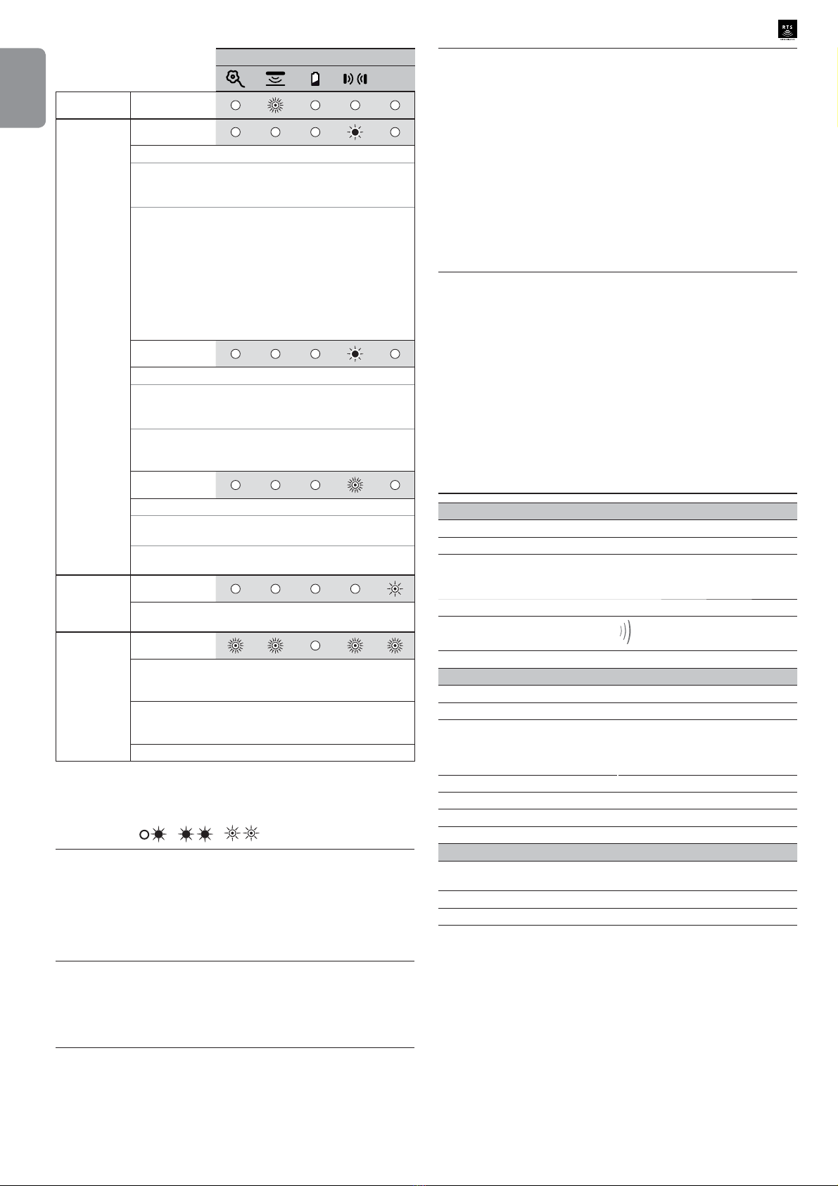
Rollixo RTS 14 - DIAGNOSTICS
14.1 Receiver
Indicator light status Meaning
Off Functional installation
6ORZÀDVKLQJ Waiting for an action/adjustment
5DSLGÀDVKLQJ Deactivation/activation in progress
Permanently lit Installation fault/failure
Indicator light status
Prog
Fall
protection Diagnostics
Fall protection is not connected or there
is no bridge on the connector if fall
protection is connected to the shared
motor terminal
Fall protection triggered
Consequences No movement possible
Actions Check the fall protection wiring (see
section 3.2).
Motor
Diagnostics Incorrectly wired motor
Consequences No movement possible
Actions Check the motor wiring (see section 3.2).
Diagnostics Fall protection triggered (when fall
protection is connected to the shared
motor terminal)
Consequences No movement possible
Actions Check the installation and replace the fall
protection.
Diagnostics Activated motor thermal protection
Consequences No movement possible
Actions Wait around 10 minutes.
Diagnostics Faulty motor or fuse blown
Consequences No movement possible and integrated
lighting off
Actions Check the condition of the fuse and
replace it if necessary (spare fuse
supplied, see section 2.2, point 13).
If the motor still does not work, replace it.
Diagnostics Waiting for motor adjustment
Actions Set the motor end limits (see section 3.4).
Optical wired
safety edge
Diagnostics Optical wired safety edge failure
Consequences Opening ok
Closing by pressing and holding down
the button within sight of the door
Actions
- Checkthetypeofsafetyedgeconnected
(optical wired safety edge, dipswitch
no.4 set to OFF); if the connected wired
safety edge is resistive, move dipswitch
no.4 to ON.
- Check the safety edge wiring (see
section 7.3).
- Check that no radio safety edge
transmitter is stored in the receiver. If a
radio safety edge transmitter is stored in
the receiver, clear it (see section 12).
Indicator light status
Prog
Resistive
wired safety
edge
Diagnostics Wired resistive safety edge failure
Consequences Opening ok
Closing by pressing and holding down
the button within sight of the door
Actions
- Checkthetypeofsafetyedgeconnected
(wired resistive safety edge, dipswitch
no.4 set to ON); if the connected wired
safety edge is optical, move dipswitch
no.4 to OFF.
- Check the safety edge wiring (see
section 7.3).
- Check that no radio safety edge
transmitter is stored in the receiver. If a
radio safety edge transmitter is stored in
the receiver, clear it (see section 12).
Diagnostics Radio safety edge failure
Consequences Opening ok
Closing by pressing and holding down
the button within sight of the door
Actions
Request movement again and if the
problem persists:
- See radio safety edge transmitters for
diagnostics (see pages 14.2).
- Repeat the safety edge transmitter
programming procedure on the receiver
(see section 10).
Diagnostics Radio interference on the safety edge
transmitter
Consequences
Opening and stopping ok
Closing by pressing and holding down
the button within sight of the door: the
closing movement will automatically
resume when the radio interference
disappears.
Radio safety
edge Actions
If a powerful radio system is present on
the site (infrared detector, TV transmitter,
etc.) and is transmitting on the same
frequency, the receiver will wait for the
transmission to end to before controlling
the door again.
Diagnostics End of life of the safety edge transmitter
batteries
Consequences Opening ok
Closing by pressing and holding down
the button within sight of the door
Actions Safety edge transmitter low battery
indication.
If the fault persists, replace the safety
edge transmitter batteries.
Diagnostics Obstacle detection
Consequences Remove the obstacle by automatic partial
opening
Actions
Check that no obstacle is causing the
safety edge to detect.
,IWKHÀRRU LVEHLQJGHWHFWHGFKHFN WKDW
WKHUHLVDPDJQHW¿WWHGDWWKHGRZQSRLQW
and install one if necessary or rectify the
ground to make it smooth and even.
14
Copyright © 2014 SOMFYACTIVITES SA.All rights reserved.
EN
Rollixo RTS
Indicator light status
Prog
Photoelectric
cells
Diagnostics Cell fault
Consequences Opening ok
Closing by pressing and holding down
the button within sight of the door
Actions
If no cells are installed, check that the
connector (terminals 18 and 19) is
bridged.
If cells are installed:
- Check that no obstacle is cutting across
the cell beam
- - Check the position of dipswitch no.2
according to the type of cell (see
section 7.2).
- Check the cell wiring (see section 7.3).
Diagnostics Bridged cell connector
Consequences Opening ok
Closing by pressing and holding down
the button within sight of the door
Actions Ifno cellsareinstalledandcellconnectors
are bridged (terminals 18 and 19), check
that dipswitch no.1 is set to OFF.
Diagnostics Obstacle detection
Consequences Remove the obstacle by full automatic
opening
Actions Check that no obstacle is cutting across
the cell beam.
Radio Diagnostics Radio frame received from a recognised
transmitter
Command Diagnostics When a key on the keypad or a remote
control button is pressed, the indicator
OLJKWVDERYHÀDVKKROLGD\PRGHLVDFWLYH
Consequences The product works but the keypad or
remotecontrolcannotbeused(depending
onthe position of dipswitch5) to control it.
Actions Deactivate holiday mode (see section 8.3).
14.2 XSE transmitter
> Problem on XSE transmitter
LED1 and LED2: / /
Step 1: CHECK THE BATTERY
Remove the battery then press a button (PROG or MODE) to discharge
WKHUHVLGXDOHQHUJ\IURPWKHHOHFWURQLFV5H¿WWKHEDWWHU\DQGZDLWIRUWKH
DXWRPDWLFEDWWHU\WHVWWREHFRPSOHWHGDQRUDQJHOLJKWÀDVKHVWRVLJQDOWKH
test is under way - it may last up to 2 minutes).
- IfLED1andLED2lightupredfor5seconds,replacethebatteryandrepeat
the operations above.
- If LED1 and LED2 light up green for 5 seconds, skip to step 2.
Step 2: CHECK THE OPERATION OF THE SAFETYEDGE
Press and hold the MODE button for 3 seconds to launch safety edge
detection.
- If LED2 lights up green then the safety edge and transmitter are operating
correctly. Squeeze the safety edge and check that LED2 lights up red.
- If not, go to step 3.
Step 3: DETERMINE THE ORIGIN OF THE FAULT: XSE TRANSMITTER
OR SAFETY EDGE?
Disconnect the safety edge.
Test 1: Press and hold the MODE button for 3 seconds to launch safety
edge detection.
- ,I/('ÀDVKHVUHGIRUVHFRQGVWKHQWKH;6(WUDQVPLWWHULVRSHUDWLQJ
correctly.
- If not, the XSE transmitter is faulty.
Test 2 (optional): Press and hold the MODE button for 3 seconds to launch
safety edge detection by short-circuiting the 2 contacts on the ESE J3
FRQQHFWRUXVLQJDÀDWEODGHVFUHZGULYHU
- If LED2 lights up red for 8 seconds then the XSE transmitter is operating
correctly.
- If not, the XSE transmitter is faulty.
If tests 1 and 2 show that the transmitter is operating correctly, replace
the safety edge.
> Problem waking up the transmitter at the Up point
Important: For each test, wait until LED2 goes off to test that the transmitter
wakes up.
Test 1: Check that the XSE transmitter is working by tapping it and check that
LED2 lights up green. If not, press and hold the PROG button for 3 seconds
and retest. If the problem persists, replace the XSE transmitter.
Test 2: 2SHQ WKH GRRU IXOO\ FKHFN WKDW D EDVH PDJQHW LV ¿WWHG DQGRU WKDW
dipswitch 3 is ON, then retest.
Test 3:,IWKHSUREOHPSHUVLVWV¿WDQXSSHUPDJQHWDQGVHWGLSVZLWFKRQWKH
XSE transmitter to ON then retest.
If the problem persists, replace the XSE transmitter.
15 - TECHNICAL DATA
GENERAL SPECIFICATIONS
Power supply 230 V - 50-60 Hz
Electrical insulation Category 1
Maximum motor output
Safety fuse for motor and integrated
lighting 230 V - 1250 W
5AT - 250 V - spare fuse supplied
Climatic operating conditions - 20°C/+ 60°C - IP20
Somfy radio frequency 433.42 MHz
< 10 mW
Number of storable remote controls 32
CONNECTIONS
Mains power supply cable 2 m - IEC sheet (phase-neutral-earth)
Integrated courtesy lighting E14 - 1.4W - 230V LED bulb
Safety inputs 3 inputs for:
- Wired safety edge: optical, resistive
- Fall protection device
- Photoelectric cells
Self-test output for safety devices For cells
Wired control input NO dry contact - sequential operation
Orange light 24V - 4W max.
Alarm siren output Yes
OPERATION
Control buttons Up-Stop-Down buttons in the control
panel
Automatic closing mode Yes
Maintenance assistance Real time status with 5 indicator lights
Copyright © 2014 SOMFYACTIVITES SA.All rights reserved.
1
PL
Rollixo RTS
63,675(Ğ&,
3U]HWâXPDF]RQDZHUVMDLQVWUXNFML 1 - =$6$'<%(=3,(&=(Ĕ67:$
1.1 2EMDğQLHQLHV\PEROL
7HQ V\PERO V\JQDOL]XMH QLHEH]SLHF]HĔVWZR
NWyUHJRUyĪQHVWRSQLHVąRSLVDQHSRQLĪHM
1,(%(=3,(&=(Ĕ67:2
6\JQDOL]XMHQLHEH]SLHF]HĔVWZRSRZRGXMąFHEH]SRĞUHGQLH
]DJURĪHQLHĪ\FLDOXESRZDĪQHREUDĪHQLDFLDáD
2675=(Ī(1,(
6\JQDOL]XMHQLHEH]SLHF]HĔVWZRPRJąFHGRSURZDG]LüGR
]DJURĪHQLDĪ\FLDOXESRZDĪQ\FKREUDĪHĔFLDáD
UWAGA
6\JQDOL]XMHQLHEH]SLHF]HĔVWZRPRJąFHGRSURZDG]LüGR
REUDĪHĔFLDáDRVWRSQLXOHNNLPOXEĞUHGQLP
:$Ī1(
6\JQDOL]XMHQLHEH]SLHF]HĔVWZRPRJąFHGRSURZDG]LüGR
uszkodzenia lub zniszczenia produktu
1.2 Wprowadzenie
> :DīQHLQIRUPDFMH
7HQ SURGXNW MHVW RGELRUQLNLHP GR EUDP JDUDĪRZ\FK
rolowanych, otwieranych pionowo, przeznaczonych do
XĪ\WNX Z RELHNWDFK PLHV]NDOQ\FK : FHOX ]DFKRZDQLD
]JRGQRĞFL ] QRUPą (1 SURGXNW WHQ QDOHĪ\
PRQWRZDüZUD]]QDSĊGHP6RPI\5'2&6,RUD]]OLVWZą
F]XMQLNRZą6RPI\&Dá\]HVWDZMHVWRNUHĞODQ\MDNR]HVSyá
QDSĊGRZ\
7HQ ]HVSyá QDSĊGRZ\ PRĪH VáXĪ\ü Z\áąF]QLH MDNR
Z\SRVDĪHQLHEUDPJDUDĪRZ\FKZRELHNWDFKPLHV]NDOQ\FK
1LQLHMV]H ]DOHFHQLD PDMą SU]HGH ZV]\VWNLP QD FHOX
VSHáQLHQLH Z\PRJyZ ZVSRPQLDQHM QRUP\ D W\P VDP\P
]DSHZQLHQLHEH]SLHF]HĔVWZDRVyELPLHQLD
2675=(Ī(1,(
8Ī\WNRZDQLH WHJR SURGXNWX SR]D ]DNUHVHP VWRVRZDQLD
opisanym w tej instrukcji jest zabronione (patrz punkt
=DNUHVVWRVRZDQLDZLQVWUXNFMLPRQWDĪX
6WRVRZDQLH MDNLFKNROZLHN DNFHVRULyZ OXE SRG]HVSRáyZ
LQQ\FKQLĪ ]DOHFDQHSU]H] ¿UPĊ6RPI\ MHVW]DEURQLRQH
SRQLHZDĪ PRJáRE\ VSRZRGRZDü ]DJURĪHQLH GOD
XĪ\WNRZQLNyZ
6RPI\ QLH EĊG]LH SRQRVLü RGSRZLHG]LDOQRĞFL ]D V]NRG\
Z\QLNáH]QLHSU]HVWU]HJDQLD]DOHFHĔSRGDQ\FKZWHM
instrukcji.
:SU]\SDGNXSRMDZLHQLDVLĊZąWSOLZRĞFLSRGF]DVPRQWDĪX
]HVSRáXQDSĊGRZHJROXEZFHOX X]\VNDQLD GRGDWNRZ\FK
LQIRUPDFML QDOHĪ\ RGZLHG]Lü VWURQĊ LQWHUQHWRZą ZZZ
somfy.com.
1LQLHMV]H]DOHFHQLDPRJąE\ü]PRG\¿NRZDQHZSU]\SDGNX
]PLDQ\QRUPOXESDUDPHWUyZ]HVSRáXQDSĊGRZHJR
=DVDG\EH]SLHF]HĕVWZD__________________________ 1
2EMDĞQLHQLHV\PEROL
1.2 Wprowadzenie 1
,QIRUPDFMDR]DJURĪHQLDFK:DĪQHLQVWUXNFMHGRW\F]ąFH
EH]SLHF]HĔVWZD
.RQWUROHZVWĊSQH
:VWĊSQDLQVWDODFMDHOHNWU\F]QD
=DOHFHQLDEH]SLHF]HĔVWZDGRW\F]ąFHPRQWDĪX
=JRGQRĞü]SU]HSLVDPL
1.8 Pomoc techniczna 3
1.9 Zapobieganie ryzyku 3
2 - Opis odbiornika Rollixo__________________________ 4
2.1 Zakres stosowania 4
2.2 Opis odbiornika 4
2SLVLQWHUIHMVXSURJUDPRZDQLD]HZQĊWU]QHJR
2.4 Wymiary 4
2.5 Schemat typowej instalacji 4
0RQWDī________________________________________ 5
3.1 Mocowanie odbiornika Rollixo 5
3U]HZRG\QDSĊGXL]DEH]SLHF]HQLDSU]HGRSDGDQLHP
3RGáąF]HQLHRGELRUQLNDGR]DVLODQLDVLHFLRZHJR
6SUDZG]HQLHNLHUXQNXREURWXQDSĊGXRUD]XVWDZLHQLDSRáRĪHĔ
NUDĔFRZ\FKQDSĊGX
0RQWDīRSW\F]QHMOXERSRURZHMOLVWZ\F]XMQLNRZHM
sterowanej falami radiowymi z nadajnikiem XSE _____ 6
0RQWDĪRSW\F]QHMOXERSRURZHMOLVWZ\F]XMQLNRZHMVWHURZDQHMIDODPL
radiowymi i jej nadajnika XSE 6
0RQWDĪGROQHJRPDJQHVXQDSURZDGQLF\
4.3 Programowanie nadajnika XSE 7
4.4 Rozpoznawanie dolnego magnesu 7
.RQWURODG]LDâDQLDRGELRUQLND_____________________ 7
']LDáDQLHZWU\ELHVHNZHQF\MQ\P
=LQWHJURZDQHRĞZLHWOHQLH
3RPDUDĔF]RZHĞZLDWáR
5.4 Fotokomórki 7
5.5 Listwa czujnikowa 7
$ODUPRSFMDZ\SRVDĪHQLD
3U]HV]NROHQLHXī\WNRZQLNyZ _____________________ 8
3RGâĆF]HQLHXU]ĆG]Hĕ]HZQċWU]Q\FK _______________ 8
7.1 Ogólny schemat okablowania 8
7.2 Ustawienie parametrów opcji przewodów 8
2SLVSRV]F]HJyOQ\FKXU]ąG]HĔ]HZQĊWU]Q\FK
=DDZDQVRZDQHXVWDZLHQLDSDUDPHWUyZ ___________ 10
5yĪQHWU\E\G]LDáDQLD
3URJUDPRZDQLHWU\EyZG]LDáDQLD
8.3 Tryb wakacyjny 11
3URJUDPRZDQLHSLORWyZ]GDOQHJRVWHURZDQLD ______ 12
9.1 Programowanie pilotów zdalnego sterowania z 2 lub 4 przyciskami 12
9.2 Programowanie pilotów zdalnego sterowania z 3 przyciskami 12
3URJUDPRZDQLHSU]H]RGWZRU]HQLHXVWDZLHĔZF]HĞQLHM
zaprogramowanego pilota zdalnego sterowania 12
10 - Programowanie nadajnika listwy czujnikowej XSE _ 12
:\NDVRZDQLHSLORWyZ]GDOQHJRVWHURZDQLD _______ 12
11.1 Wykasowanie jednego pilota zdalnego sterowania 12
11.2 Wykasowanie wszystkich pilotów zdalnego sterowania 12
12 - Wykasowanie nadajnika listwy czujnikowej _______ 13
%ORNRZDQLH2GEORNRZDQLHSU]\FLVNyZSURJUDPRZDQLD
________________________________________________ 13
14 - Diagnostyka _________________________________ 13
14.1 Odbiornik 13
14.2 Nadajnik XSE 15
15 - Dane techniczne______________________________ 15

2
Copyright © 2014 SOMFYACTIVITES SA.All rights reserved.
PL
Rollixo RTS
1.3 ,QIRUPDFMDR]DJURīHQLDFK:DīQHLQVWUXNFMH
GRW\F]ĆFHEH]SLHF]HĕVWZD
1,(%(=3,(&=(Ĕ67:2
=HVSyáQDSĊGRZ\PXVLE\üPRQWRZDQ\LXVWDZLDQ\SU]H]
SURIHVMRQDOQHJRLQVWDODWRUDVSHFMDOL]XMąFHJRVLĊZ]DNUHVLH
XU]ąG]HĔ PHFKDQLF]Q\FK L DXWRPDW\NL Z EXG\QNDFK
PLHV]NDOQ\FK ]JRGQLH ] SU]HSLVDPL RERZLą]XMąF\PL Z
NUDMXZNWyU\PEĊG]LHXĪ\WNRZDQ\
1LHSU]HVWU]HJDQLH W\FK ]DOHFHĔ PRJáRE\ VSRZRGRZDü
SRZDĪQHREUDĪHQLDXRVyEQDSU]\NáDGLFKSU]\JQLHFHQLH
EUDPą
2675=(Ī(1,(
,QIRUPDFMDR]DJURĪHQLDFK:DĪQHLQVWUXNFMHGRW\F]ąFH
EH]SLHF]HĔVWZD
3U]HVWU]HJDQLH ZV]\VWNLFK SRGDQ\FK ]DOHFHĔ MHVW
RJURPQLH ZDĪQH ]H Z]JOĊGX QD EH]SLHF]HĔVWZR OXG]L
SRQLHZDĪ QLHSUDZLGáRZ\ PRQWDĪ PRĪH VSRZRGRZDü
SRZDĪQHREUDĪHQLDFLDáD,QVWUXNFMHWHQDOHĪ\]DFKRZDü
2VRED Z\NRQXMąFD PRQWDĪ PXVL NRQLHF]QLH SU]HV]NROLü
ZV]\VWNLFKXĪ\WNRZQLNyZDE\]DSHZQLüSHáQHEH]SLHF]HĔVWZR
XĪ\WNRZDQLDQDSĊGX]JRGQLH]LQVWUXNFMąREVáXJL
,QVWUXNFMD REVáXJL RUD] LQVWUXNFMD PRQWDĪX SRZLQQ\
]RVWDü SU]HND]DQH NRĔFRZHPX XĪ\WNRZQLNRZL 1DOHĪ\
MDVQRZ\WáXPDF]\üXĪ\WNRZQLNRZLĪHPRQWDĪUHJXODFMD
L NRQVHUZDFMD PXV]ą E\ü SRZLHU]DQH SURIHVMRQDOQHPX
LQVWDODWRURZL VSHFMDOL]XMąFHPX VLĊ Z ]DNUHVLH XU]ąG]HĔ
mechanicznych i automatyki w budynkach mieszkalnych.
1.4 .RQWUROHZVWċSQH
> Otoczenie instalacji
:$Ī1(
1LHSROHZDü]HVSRáXQDSĊGRZHJRZRGą
1LH PRQWRZDü ]HVSRáX QDSĊGRZHJR Z PLHMVFDFK Z
NWyU\FKZ\VWĊSXMHU\]\NRZ\EXFKX
6SUDZG]LüF]\]DNUHVWHPSHUDWXU\]D]QDF]RQ\QD]HVSROH
QDSĊGRZ\PMHVWGRVWRVRZDQ\GRPLHMVFDPRQWDĪXQDSĊGX
> 6WDQEUDP\GRNWyUHMMHVWSU]H]QDF]RQ\QDSċG
3DWU]]DOHFHQLDEH]SLHF]HĔVWZDGRW\F]ąFHQDSĊGX5'2&6,
1.5 :VWċSQDLQVWDODFMDHOHNWU\F]QD
1,(%(=3,(&=(Ĕ67:2
,QVWDODFMD ]DVLODQLD HOHNWU\F]QHJR PXVL E\ü ]JRGQD ]
QRUPDPLRERZLą]XMąF\PLZNUDMXZNWyU\P]DLQVWDORZDQR
]HVSyá QDSĊGRZ\ L SRZLQQD E\ü Z\NRQDQD SU]H]
Z\NZDOL¿NRZDQ\SHUVRQHO
8NáDG HOHNWU\F]Q\ PXVL E\ü SU]H]QDF]RQ\ Z\áąF]QLH GR
]HVSRáX QDSĊGRZHJR L Z\SRVDĪRQ\ Z ]DEH]SLHF]HQLH
VNáDGDMąFHVLĊ]QDVWĊSXMąF\FKHOHPHQWyZ
- EH]SLHF]QLNOXEVDPRF]\QQ\Z\áąF]QLN$
- LXU]ąG]HQLHW\SXUyĪQLFRZHJRP$
1DOHĪ\]DSHZQLüPRĪOLZRĞüZLHORELHJXQRZHJRRGáąF]DQLD
zasilania.
Zalecane jest zamontowanie odgromnika (maksymalne
QDSLĊFLHV]F]ąWNRZHN9
> 8âRīHQLHSU]HZRGyZ
3U]HZRG\ ]DNRSDQH Z ]LHPL PXV]ą E\ü Z\SRVDĪRQH
Z RVáRQĊ R ĞUHGQLF\ Z\VWDUF]DMąFHM QD XáRĪHQLH Z QLHM
SU]HZRGXQDSĊGXRUD]SU]HZRGyZDNFHVRULyZ
:SU]\SDGNXSU]HZRGyZNWyUHQLHVąSRSURZDG]RQHSRG
]LHPLąXĪ\üSU]HORWNLNWyUDZ\WU]\PDSU]HMD]GSRMD]GyZQU
kat. 2400484).
1.6 =DOHFHQLDEH]SLHF]HĕVWZDGRW\F]ĆFHPRQWDīX
1,(%(=3,(&=(Ĕ67:2
1LHSRGáąF]Dü ]HVSRáXQDSĊGRZHJR GRĨUyGáD ]DVLODQLD
SU]HG]DNRĔF]HQLHPPRQWDĪX
2675=(Ī(1,(
8SHZQLü VLĊ ĪH VWUHI\ PLĊG]\ F]ĊĞFLą QDSĊG]DQą D
]ORNDOL]RZDQ\PL Z SREOLĪX HOHPHQWDPL QLHUXFKRP\PL
VWZDU]DMąFH]DJURĪHQLH]ZLą]DQH]SU]HVXZDQLHPVLĊF]ĊĞFL
QDSĊG]DQHM SRGF]DV RWZLHUDQLD SU]\JQLHFHQLH SU]\FLĊFLH
]DNOHV]F]HQLH ]RVWDá\ Z\HOLPLQRZDQH OXE R]QDNRZDQH Z
REUĊELHLQVWDODFML(patrzpunkt "Zapobieganie ryzyku").
2675=(Ī(1,(
Wprowadzanie zmian do któregokolwiek z elementów
GRVWDUF]RQ\FKZW\P]HVWDZLHOXEXĪ\ZDQLHMDNLHJRNROZLHN
dodatkowego elementu, który nie jest zalecany w tej
instrukcji, jest surowo wzbronione.
2EVHUZRZDüRWZLHUDQLHOXE]DP\NDQLHEUDP\LSLOQRZDü
DE\ZV]\VWNLHRVRE\SR]RVWDZDá\ZEH]SLHF]QHMRGOHJáRĞFL
GRPRPHQWX]DNRĔF]HQLDPRQWDĪX
1LHVWRVRZDüĞURGNyZNOHMąF\FKGR]DPRFRZDQLD]HVSRáX
QDSĊGRZHJR
:$Ī1(
0RQWRZDü VWDáH XU]ąG]HQLD VWHUXMąFH QD Z\VRNRĞFL FR
najmniej 1,5 m, w miejscu, z którego brama jest dobrze
ZLGRF]QDOHF]]GDODRGUXFKRP\FKF]ĊĞFL
3R]DNRĔF]HQLXLQVWDODFMLXSHZQLüVLĊĪH
- PHFKDQL]PMHVWSUDZLGáRZRZ\UHJXORZDQ\
- QDSĊG]PLHQLDNLHUXQHNUXFKXEUDP\JG\QDSRWNDRQD
SU]HV]NRGĊQDZ\VRNRĞFLPPRGSR]LRPXSRGáRĪD
2675=(Ī(1,(
,1)250$&-$2=$*52ĩ(1,8%UDPDDXWRPDW\F]QD±
%UDPDPRĪH]DF]ąüSRUXV]DüVLĊZVSRVyEQLHRF]HNLZDQ\
GODWHJRQDMHMWRU]HUXFKXQLHQDOHĪ\SR]RVWDZLDüĪDGQ\FK
przedmiotów.
> 8U]ĆG]HQLD]DEH]SLHF]DMĆFH
1,(%(=3,(&=(Ĕ67:2
2ERZLą]NRZR QDOHĪ\ ]DLQVWDORZDü XU]ąG]HQLH
]DSRELHJDMąFH QLHNRQWURORZDQHPX RSXV]F]DQLX VLĊ
EUDP\GRVWRVRZDQHGRMHMFLĊĪDUXDE\]DSRELHFU\]\NX
RSDGQLĊFLDSáDV]F]DEUDP\
Copyright © 2014 SOMFYACTIVITES SA.All rights reserved.
3
PL
Rollixo RTS
2675=(Ī(1,(
: SU]\SDGNX G]LDáDQLD EUDP\ Z WU\ELH DXWRPDW\F]Q\P
OXEZV\WXDFMLJG\XU]ąG]HQLHVWHUXMąFH]QDMGXMHVLĊSR]D
SROHPZLG]HQLDQDOHĪ\]DLQVWDORZDüIRWRNRPyUNL
=HVSyá QDSĊGRZ\ DXWRPDW\F]Q\ WR WDNL NWyU\ G]LDáD
przynajmniej w jednym kierunku bez celowej aktywacji
SU]H]XĪ\WNRZQLND
2675=(Ī(1,(
:SU]\SDGNXXUXFKDPLDQLDEUDP\SRSU]H]QDFLĞQLĊFLHL
SU]\WU]\PDQLHSU]\FLVNXZQDVWĊSVWZLHXVWHUNLXU]ąG]HQLD
]DEH]SLHF]DMąFHJR QDOHĪ\ NRQLHF]QLH NRQWURORZDü
wzrokowo ruch bramy.
:SU]\SDGNXG]LDáDQLDEUDP\ZWU\ELHDXWRPDW\F]Q\PDOER
JG\ EUDPD JDUDĪX Z\FKRG]L QD GURJĊ SXEOLF]Qą PRĪH
E\ü NRQLHF]QH ]DPRQWRZDQLH SRPDUDĔF]RZHJR ĞZLDWáD
]JRGQLH ] SU]HSLVDPL RERZLą]XMąF\PL Z NUDMX Z NWyU\P
]HVSyáQDSĊGRZ\EĊG]LHXĪ\WNRZDQ\
> =DOHFHQLDGRW\F]ĆFHXELRUX
1D F]DV PRQWDĪX QDOHĪ\ ]GMąü ZV]HONą ELĪXWHULĊ
EUDQVROHWNDáDĔFXV]HNOXELQQD
3U]\ Z\NRQ\ZDQLX ZV]HONLFK F]\QQRĞFL RUD] ZLHUFHQLX L
VSDZDQLX XĪ\ZDü VWRVRZQ\FK ]DEH]SLHF]HĔ VSHFMDOQH
RNXODU\RFKURQQHUĊNDZLFHQDXV]QLNLRFKURQQHLWG
1.7 =JRGQRğý]SU]HSLVDPL
)LUPD 6RPI\ RĞZLDGF]D QLQLHMV]\P ĪH SURGXNW RSLVDQ\
Z WHM LQVWUXNFML R LOH MHVW XĪ\ZDQ\ ]JRGQLH ] SRGDQ\PL
]DOHFHQLDPLVSHáQLD ]DVDGQLF]HZ\PRJLRERZLą]XMąF\FK
'\UHNW\Z (XURSHMVNLFK D Z V]F]HJyOQRĞFL '\UHNW\Z\
0DV]\QRZHM :( RUD] '\UHNW\Z\ GRW XU]ąG]HĔ
radiowych 2014/53/UE.
3HáQ\ WHNVW GHNODUDFML ]JRGQRĞFL :( MHVW GRVWĊSQ\ SRG
QDVWĊSXMąF\P DGUHVHP LQWHUQHWRZ\P ZZZVRPI\FRP
FH$QWRLQH&5(=(0DQDJHUGV]JRGQRĞFL]SU]HSLVDPL
Cluses.
1.8 Pomoc techniczna
0RĪHVLĊ]GDU]\üĪHSRGF]DVPRQWDĪX]HVSRáXQDSĊGRZHJR
SRMDZLąVLĊWUXGQRĞFLOXEGRGDWNRZHZąWSOLZRĞFL
:WDNLPSU]\SDGNX SURVLP\RNRQWDNWD QDVLVSHFMDOLĞFL
XG]LHOą3DĔVWZXRGSRZLHG]LQDZV]HONLHS\WDQLD
Internet:www.somfy.com
1.9 Zapobieganie ryzyku
2675=(Ī(1,(
=DSRELHJDQLHU\]\NXQDSċGGREUDP\JDUDīRZHM
URORZDQHMSU]H]QDF]RQHMGRXī\WNXZRELHNWDFK
mieszkalnych
> 6WUHI\QLHEH]SLHF]QHMDNLHğURGNLQDOHī\SRGMĆý
DE\MHZ\HOLPLQRZDý"
Strefa 1
Strefa 2
Strefa 3
Strefa 4
RYZYKO 52=:,ą=$1,(
STREFA1
Ryzyko przygniecenia
przy zamykaniu
PLĊG]\SRGáRĪHP
DGROQąNUDZĊG]Lą
SáDV]F]DEUDP\
Wykrycie przeszkody przez
OLVWZĊF]XMQLNRZąKoniecznie
SRWZLHUG]Lü ĪH V\VWHP
wykrywania przeszkód jest
zgodny z aneksem A normy
EN 12 453
:SU]\SDGNXG]LDáDQLDEUDP\
w trybie automatycznego
]DP\NDQLD QDOHĪ\
]DLQVWDORZDü IRWRNRPyUNL
SDWU]LQVWUXNFMDPRQWDĪX
STREFA2*
Ryzyko zakleszczenia
SRPLĊG]\VNU]\QNąL
SáDV]F]HPEUDP\
:\HOLPLQRZDü ZV]HONLH
V]F]HOLQ\ PP OXE
PP SRPLĊG]\ VNU]\QNą D
SáDV]F]HPEUDP\
STREFA3*
Ryzyko skaleczenia i
]DNOHV]F]HQLDPLĊG]\
ODPHODPLSáDV]F]D
bramy w szczelinach
o wymiarach
ZDKDMąF\FKVLĊRG
mm do 25 mm
:\HOLPLQRZDü ZV]HONLH
Z\VWDMąFH HOHPHQW\ RUD]
ZV]\VWNLH RVWUH NUDZĊG]LH
SRZLHU]FKQLSáDV]F]DEUDP\
:\HOLPLQRZDü ZV]\VWNLH
V]F]HOLQ\ R Z\PLDUDFK
PPOXEPP
STREFA4*
Ryzyko zakleszczenia
SRPLĊG]\
prowadnicami i
SáDV]F]HPEUDP\
8VXQąü ZV]\VWNLH RVWUH
NUDZĊG]LHSURZDGQLF
:\HOLPLQRZDü ZV]\VWNLH
V]F]HOLQ\ PP SRPLĊG]\
SURZDGQLFDPL D SáDV]F]HP
bramy
: SU]\SDGNX VWUHI L QLH MHVW Z\PDJDQH ĪDGQH
]DEH]SLHF]HQLH MHĪHOL EUDPD MHVW VWHURZDQD Z WU\ELH
FLąJá\P OXE MHĪHOL VWUHID QLHEH]SLHF]QD ]QDMGXMH VLĊ
QD Z\VRNRĞFL SRZ\ĪHM P Z]JOĊGHP SRGáRĪD OXE
MDNLHJRNROZLHNLQQHJRSR]LRPXVWDáHJRGRVWĊSX

4
Copyright © 2014 SOMFYACTIVITES SA.All rights reserved.
PL
Rollixo RTS
2 - OPIS ODBIORNIKAROLLIXO
2.1 Zakres stosowania
2GELRUQLN52//,;2ZUD]]QDSĊGHP6RPI\5'2&6,RUD]OLVWZąF]XMQLNRZą
6RPI\ ]RVWDá RSUDFRZDQ\ GR QDSĊG]DQLD EUDP JDUDĪRZ\FK URORZDQ\FK
RWZLHUDQ\FKSLRQRZRSU]H]QDF]RQ\FKGRXĪ\WNXZRELHNWDFKPLHV]NDOQ\FK
RZ\PLDUDFK]HZQĊWU]Q\FK
- :\VRNRĞü PDNVLPXPP
- 6]HURNRĞü PDNVLPXPP
2.2 Opis odbiornika
34
2
1
Prog
STOP
1
2
3
4
5
6
7
8
11
9
13
12
10
14
Ozn. Nazwa
1ĩDUyZND]LQWHJURZDQHJRRĞZLHWOHQLD
22VáRQDRGELRUQLND
3ĝUXEDRVáRQ\RGELRUQLND
4,QWHUIHMVSURJUDPRZDQLD]HZQĊWU]QHJR
5,QWHUIHMVSURJUDPRZDQLDZHZQĊWU]QHJR
6 Antena 433,42 MHz
72GáąF]DQHOLVWZ\]DFLVNRZH
8 Uchwyt przewodu
9ĝUXEDXFKZ\WXSU]HZRGX
10 ĝUXEDPRFXMąFDDODUP
11 Zwora zabezpieczenia przed opadaniem
12 %H]SLHF]QLNQDSĊGXL]LQWHJURZDQHJRRĞZLHWOHQLD
13 Bezpiecznik zamienny
14 ĩDUyZND/('(:9
2.3 2SLVLQWHUIHMVXSURJUDPRZDQLD]HZQċWU]QHJR
3 421
Prog
STOP
1
2
3
678 9
5
4
Ozn. Nazwa Funkcja
1 Przycisk Góra Otwarcie bramy
2 Przycisk STOP Zatrzymanie bramy
33U]\FLVN'yá =DPNQLĊFLHEUDP\
4 Przycisk Prog Programowanie nadajników radiowych
5 Kontrolka Prog ,QIRUPDFMDGRW\F]ąFDRGELRUXIDO
radiowych i programowania nadajników
radiowych
6.RQWURONDQDSĊGXL
zabezpieczenia przed
opadaniem
,QIRUPDFMDRVWDQLHQDSĊGX
zabezpieczenia przed opadaniem
7 Kontrolka listwy
czujnikowej Informacja o stanie listwy czujnikowej,
nadajnika listwy czujnikowej
8 Kontrolka akumulatora Informacja o stanie akumulatora nadajnika
listwy czujnikowej
9 Kontrolka fotokomórek Informacja o stanie fotokomórek
2.4 Wymiary
60,6 157,7
182,7
261,9
2.5 Schemat typowej instalacji
1DSċG Odbiornik
Listwa czujnikowa
Nadajnik listwy
czujnikowej
Zabezpieczenie
przed opadaniem
Table of contents
Languages:
Other SOMFY Door Opening System manuals


