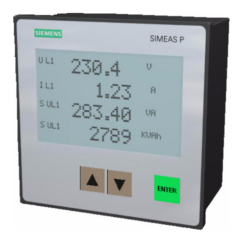
SOMMY EW9L Series User manual

EW9系列三相智能电量仪表操作说明书
Voltage Consumption
Voltage Overload
Connection
Features:
EW9L Series 3 Phase Energy Meter Operation Manual
Model
Model Illustration
Technical Parameters
Harmonic TariffCommunicationTransformed analog outputAlarmModel
⊙
Measurement Parameters: 3 phase Voltage/Current/Active power/Reactive power/Frequency/Power factor ect , 28 parameters.
⊙Four switch signal input, two switch signal output; isolation for input and output.
⊙
Ture effective value measuring;
⊙
With programmable analog output function , analog output for voltage/current/active power/reactive power/fequency/power factor.
⊙
With RS485 connection and Modbus RTU communication protocol.
⊙
With 2 loops
active power/reactive power
energy pulse output, 2 programmable alarm, display programmable setted parameters
.
⊙
With power failure function for display menu select/KWH/KvarH
Voltage Range
!Warning: any operation not following the manual will cause accident and damage to the product.
Statement: Information provided in this manual can be modified without prior notice.
The company reserves the right of interpretation of the information.
page 1/15
⊙Optional tariff statistics function, with demand statistics function.
⊙Optional harmonic analysis funtion (including the total harmonic).
EW9L-□-C
EW9L-□-S
EW9L-□-F
EW9L-□-H
No
No
No
4 ~ 20mA No No
No No
No
NoYes
Yes
1 loop RS485
1 loop RS485
1 loop RS485
2 loop RS485
2
2
2
2
3 phase 3 wires, 3 phase 4 wires
AC 3x57.7V / 3X220V (note: Direct input volt: L-N: 0~600V, L-L: 0~1000V)
<1VA (each phase)
E W 9 L □ □ C/S/F/H
Display: L: LCD display T: TFT color LCD display
Measurement type: W: 3 phase integrated measurement P: 3 phase voltage/ current/ active power
S: 3 phase voltage/ current
Measuring Range: A: 100V/5A Blank: 400V/5A (default range) C: custom range
Dimension: 9: 96H×96W×104.6L(mm)
EW Series 3 phase energy meter
Extensions: C: 4~20mA analog output S: two loops RS485 communication (If select this function,
there would be two less DI connection) F: With Multi-tarrif rate function H: Harmonics measurement
measurement
The energy meters are widely applied to control system, SCADA system and energy management system, transformer substation automation,
distributing net automation, community electrical power monitor, industrial automation, intelligent construction, intelligent switchboard, switch
cabinet, etc. It is esay to install and maintain, simple connection, filed programmable setting input parameters.
Continuous: 1.2 times Instantaneous: 2 times/10S
⊙With neutrual line measurement function.
KKEW9LC05-A/0-20160901

KKEW9LC05-A/0-20160901
Panel Indication
1
2
3
4
5
6
U
A
P
F
E
EP
EN
E
EP
EN
page 2 /15
≥300KΩ
AC 0.025 ~ 5A
<0.4VA (each phase)
<20mΩ
AC/DC 100 ~ 240V (85 ~ 265V)
≤7VA
-25 ~ 70℃
96W×96H×104.6L(mm)
0.6kg
Voltage impedance
Voltage Accuracy
Current Range
Current Overload
RMS measurement , Accuracy : 0.5
Continuous: 1.2 times Instantaneous: 10 times/10S
Current Consumption
Current impedance
RMS measurement , Accuracy : 0.5
Current Accuracy
Frequency 30-500Hz , Accuracy: 0.1Hz
Power Active power/Reactive power/Apparent power, accuracy: 0.5
Energy Active power accuracy 0.5 / Reactive power accuracy 1.
Display
LCD Display (can select blue backlight, white backlight as default)
Power Supply
Power Supply Consumption
RS-485 Modbus-RTU Protocol
Output Digit Interface
Pulse Output 2 energy pulse output (optical coupler relay) Normal Pulse constant: 9000imp/kwh
On/Off Input
Alarm Output
Analog Output
Working Environment
Storage Environment
Isolation & puncture
Insulation
Dimension
Weight
4 On/Off input (connection without voltage or current signal)
2 On/Off output, 250VAC/3A or 30V DC/5A
1 transformed analog output, 4-20mA DC Load<500Ω
Temperature: -10 ~ 50℃, Humidity: <85% RH; no corrosive gas; altitude ≤ 2500m
Input signal and power 1600V AC , Input and output 1600VAC , power and transformed analog output, RS485
connection , DI connection , Pulse output connection≥DC 2000V
Input/output/power supply to Meter cover >5MΩ
Symbol Meaning
voltage
current
power
Frequency
No. symbol Name Function
Set Key
Check measuring value and working status indication:
1. Under measuring status , press / key to shift display of 3 phase voltage, 3 phase linear voltage, 3 phase current, total power, frequency, etc.
2. Press key / to shift display of Kwh and KvarH. (When second harmonic enable, use ESC to shift display of energy.)
3. Under alarm mode , DO1 and DO2 is used as alarm output status indication. Under ON/OFF remote control mode , DO1 and DO2 is used as
ON/OFF output status indication.
4. S1, S2, S3, S4 indicate switch signal remote control input status.
5. Alarm flash means alarm output, COM flash means communicating, RUN move means the meter is under measuring status.
6. E (kwh) means total active energy, E (kvarh) means total reactive energy.
Forward kvarh
Forward kwh
Inverse kwh
Total kwh
Total kvarh
Inverse kvarh
Left Key
Right Key
Decrease Key
Increase Key
Return Key
Press this key more than 3 seconds to enter the menu
Confirm the set value
In menu operation, it can shift menu
Change to display left page
In menu operation, it can shift menu
Change to display right page
In menu operation, it is used to enter data setting
Decrease value
In menu operation, it is used to enter data setting
Increase value
In menu operation, it is used to return to previous menu
2
3
1
4
5
6
v
v
v
a
b
c
M Wh
Intelligent Meter
S E T E SC
SET
ESC

page 3/15 KKEW9LC05-A/0-20160901
SET SET
SET
/
primary volt setting
secondary current setting
SET
SET
SET
SET
/
/
/
SET
SET
/
/
SET
/
software version
/
SET
/
Shift measurement interface operation :
3 phase volt ( phase volt or line volt) 3 phase current Total power / power factor power factor , frequency
maximum demand demand
Total current harmonics
percentage
Total voltage
harmonics
percentage
A Phase
parameters
B Phase
parameters
C Phase
parameters
Measuring Status
Menu Operation press SET
more than
5 seconds
First class Second class Third class
After modifying data, press key SET
for confirmation and press ESC key
return to previous menu.
System setting
flash
flash
flash
flash
Remove Kwh code setting
User password setting
backlight delay time
Page shift time
Signal input
flash
flash
flash
flash
flash
Choose input net
secondary volt setting
primary current setting

page 4/15 KKEW9LC05-A/0-20160901
SET
SET
SET
SET
SET
SET
/
/
/
/
SET
/
/
SETSET
SET
/
/
SET
/
SET
/
SET
/
SET
SET
SET
SET
/
/
/
/
/
SET
SET
/
SETSET
/
SET
/
flash
flash
flash
flash
flash
flash
flash
flash
flash
flash
flash
flash
flash
flash
flash
flash
flash
flash
flash
Communication
parameters
Meter’s address range
Baud Rate
Data format
1st Alarm mode
1st Alarm unit
1st alarm value setting
1st alarm Hysteresis value setting
1st alarm relay
output choice
1st alarm start delay
1st alarm finish delay
2nd alarm mode
2nd alarm unit
2nd alarm value setting
2nd alarm Hysteresis value setting
2nd alarm relay
output choice
2nd alarm start delay
2nd alarm finish delay
1st transmit mode
1st transmit unit
transmition output
switch signal
setting

page 5/15 KKEW9LC05-A/0-20160901
SET
SET
SET
/
/
/
SET
/
SET
/
/
SET
SET
SET
/
/
SET
SET
/
SET
SET
SET
/
/
/
SET
SET
/
/
/
A B CD E F GH I J K LM
N O PQ R S TUVW X YZ
flash
flash
flash
flash
flash
flash
flash
flash
flash
flash
flash
flash
flash
flash
1st transmition high limit value
1st transmition low limit value
year
Month
Day
Hour
Minute
Second
Period 1 tarrif rate
Period 2 tarrif rate
Period 12 tarrif rate
Tariff rate setting
Time setting
note: 26 English letters display method on LED
letter
letter
display method
display method
period 1 start time
period 2 start time
period 12 start time

page 6/15 KKEW9LC05-A/0-20160901
1
2
/
/ /
/
4
3
/
/ /
/
/
Menu Operation Illustration
Under user menu status
1. Press SET key more than 5 seconds to enter user menu; if the user password is set, it will pop up the password input box, enter the correct
password to enter the user menu, and then set the parameters.
2. If the current display is the first class, press SET key to enter next class display. Press to change other parameters.
3. If the current display is second or third class , press ESC key to return to previous class display.
4. If the current display is third class , press key to flash digit, press key to shift place. Keep pressing to change value . Press
SET key to save value. If press ESC key, do not save the set value and return to second class.
5. After modifying the parameters , press SET key more than 5 seconds or press ESC key, to exit user menu, return to measuring status.
Menu Structure and Function Description
No. class 1 class 2 class 3 description
System
Setting
Clear Energy
User password
backlight
delay time
page shift time
software version
Input net
Volt transform
Volt transform
Current
transform
Current
transform
signal input
Communication
parameter
Switch signal
setting
Address
baud rate
Data sequence
Alarm mode
Alarm unit
Alarm value
Alarm hysteresis
value
alarm relay
setting
alarm start
delay
alarm finish
delay
Alarm mode
Alarm unit
Alarm value
Alarm hysteresis
value
alarm relay
setting
alarm start
delay
alarm finish
delay
Input “ 1111” to clear energy. Input 2222 to clear maximum demand.
input 1234 to reset to factory setting
Change user password
backlight delay time , unit is second . If set as 0 , mean keep on
lighting all the time.
measurement page shift delay time , unit is second . If set as 0, no
page shift.
software version
Select the input network of the measured signal
Primary coil voltage , unit kV
Secondary coil voltage , unit V
Primary coil current , unit A
Secondary coil current ,unit A
meter address range
Baud rate: 4k8 means 4800, 9k6 means 9600
Data sequence: high digit in front or low digit in front
When the value is 0 , it is for remote control mode, otherwise
it is for alarm mode. Please refer to table 1.
1: means international standard unit, K: means 1000 times of
international standard unit, M: means1000000
times of international standard unit.
1st alarm value setting
1st alarm hysteresis value setting
1st alarm relay output setting
alarm start delay time , unit : second
alarm finish delay time , unit : second
When the value is 0 , it is for remote control mode, otherwise
it is for alarm mode. Please refer to table 1.
1: means international standard unit, K: means 1000 times of
international standard unit, M: means1000000
times of international standard unit.
2nd alarm value setting
2nd alarm hysteresis value setting
2nd alarm relay output setting
alarm start delay time , unit : second
alarm finish delay time , unit : second

page 7/15 KKEW9LC05-A/0-20160901
7
6
5
/ /
Analog
output
transmit mode
selection
transmit value
unit
transmit high
limit
transmit low limit
Year
Month
Day
Hour
Minute
Second
Please refer to table 1
1: means international standard unit, K: means 1000
times of international standard unit, M: means1000000
times of international standard unit.
Transmit output 20mA
Transmit output 4mA
Year
Month
Day
Hour
Minute
Second
Tariff Setting
Time setting
Period 1 tariff
Period 2 tariff
Period 12 tariff
Period 1 start time
Period 2 start time
Period 12 start time
Period 1 tariff means
Sharp tariff, Peak tariff, flat tariff, valley tariff
Period 2 tariff means
Sharp tariff, Peak tariff, flat tariff, valley tariff
Period 12 tariff means
Sharp tariff, Peak tariff,
middle tariff, valley tariff
Period 1 start time Note
Period 2 start time Note
Period 12 start time Note
:Divide 24 hours a day into 96 segments, every 15 minutes as one segments. For example, the corresponding time for segment 0 is 0 o'clock,
the corresponding time for segment 10 is 2:30. Please notice that, the setting of period 1 to period 12 should be from small to big.
Note
Output Function
1. Energy pulse
EW9L provides the function of energy calculation, with 2 energy pluse output AP & RP, and RS485 interface for the transmit of energy data.
The energy pulse of optical couple relay with open collector enables the long distance transmit of active energy AP & reactive energy RP. Remote
PC terminal, PLC, DI On-Off output and collector module are applied to collect the pulse of energy meter to enable the energy cumulation
calculation. Besides, this output mode is also the energy accuracy check way (National metrology regulations: Standard meter pulse tolerance
comparison method)
(1). Electrical characteristic: the output of optical couple relay with open collector , V≤ 48V, Iz≤ 50mA
(2). Pulse constant: 9000imp/kwh. It means the impulse output No. is 9000 when the energy meter counts up to 1KWH.
The piont should be emphasized is that the above 1kwh is for the 2nd coil energy. Supposed that PT and CT is connected , the primary coil energy
that 9000 pulse refer to is equal to 1kwhX voltage transform PT X current transform CT.
2. Remote measure and remote control function: 4 loops S1-S4 are used to remote measure electric ON/OFF status. DO1 & DO2 function can be
used to remote control electric devices. When using Do function, alarm mode should be setted as 0, otherwise DO1 and DO2 will be as AL1, AL2
output. DO1 DO2 function control value is writen via RS485 interface.
3. Communication function ( please refer to the communication protocol)
4. Transform output( please refer to table 1)
5. Alarm function (please refer to table 1)

page 8/15 KKEW9LC05-A/0-20160901
一、MODBUS serial communication protocol
1 18 No
EW9L series energy meter adopts Modbus RTU communication protocol RS485 half duplex communication , read function code 0x03,
write function code 0x10 , adopts 16 digit CRC check, the energy meter does not feedback the check error.
Start bit Data bit Stop bit Check bit
Communication protocol
(1) All the RS485 communication should comply with host/slave method. Under this method, information and data is transmitted between one host
and maximum 32 slaves (monitoring equipment);
(2) Host will initialize and control all information transmitted in RS485 communication circuit.
(3) In any case, communication can never be started from a slave.
(4) All the RS485 communication is sending by packet . One data packet is a simple string (every string has 8 bit). One packet include 128 byte
at most. The bytes in the packet formed in standard asynchronous serial data , and transmitting in the mode of 8 data bits, 1 stop bit, no check bit.
(5) Host sending is called request, slave sending is called response.
(6) In any case, slave can only respond to one request of host.
2. Each MODBUS data packet is consisted several parts as below:
(1) Slave address; (2) Function code to be executed; (3) Register address (variate address); (4) Data; (5) CRC check;
(1) Slave address: address length is 1 byte, effective slave address range is 1-247, if slave receives a data packet, whose frame address information
is consonant with its own address information , it will execute the order of data packet.
(2) Function code length in MODBUS data packet is one byte, used to inform the slave what kind of operation needs to be executed. The slave
response data packet should have the same function code byte of the operation requested by host.
Please refer to below table for related function code:
Transmitting package in RS485 network should follow the time regulation as follows:
(1) When baud rate set as 9600, the delay time between two host request is recommended to be 300ms or more, lesser time may cause the
loss of data packet.
(2) When the recommended baud rate is 9600, if use smaller baud rate, please enlarge delay time properly. For example, when baud rate is 2400,
two request should be set as more than 500ms.
II. Network time consideration
III. Abnormal communication processing
If host send a illegal data packet or host request a invalid data register, abnormal data response will happen. This abnormal data response is
consisted of slave address, function code, error code and check area. When the high bit position of function code area is 1, it means the present
data frame is abnormal response.
Below table illustrates the meaning of abnormal function code:
According to MODBUS communication requirement, abnormal response function code=request function code+0x80; when abnormal response,
put 1 on the highest bit of function code. For example: if host request function code is 0x04, slave response function code is 0x84.
0x01 Function code error Meter received the unsupported function code
Variable address error Data location designated by host exceeds range of meter, or receive illegal register operation.
Variable value error Data value sent from host exceeds the corresponding data range of meter, or data structure is incomplete
0x02
0x03
0x03 Read register
0x06
Write single-register
(3) Register address variable: data area storage location when slave executes effective order. Different variable seizes differents numbers of
register, some address variable seizes two register, 4 byte data, somevariable seizes one register, 2 byte data, please use according to
actual situation.
(4) Data area: data area includes the data required by terminal to execute specified function or collected data when terminal respond to query.
The content of the data could be numerical value, reference address or set value; for example: function code tells terminal to read a register,
data area needs to indicate which register to started from and how much data to be read, embedded address and data will be different
according to different content between type and slave; register numerical value send sequence : high byte in the front, low byte in the back.
(5) CRC check: MODBUS-RTU mode adopts 16 bit CRC check. Sending equipment should do CRC16 calculation for each data of packet,
final result is stored in check area. Receiving equipment also make CRC16 calculation for each data of packet (except check area), and
compare result area with check area; only the same packet can be accepted, for the specific CRC check algorithm please refer to appendix.
0x10 Write multi-register
Read one or more present register value
Write specified value into one internal register
Write specified value into several internal registers (Factory default write single register)
Function code Meaning Function
Error code type Name Contents illustration
1. Read multi-register
For example, host reads UA (A phase voltage), suppose measured A phase voltage is 220.0V.
The address code of UA is 0x4000, because UA is fixed data (4 byte), seizes 2 data register, the hexadecimal data of 220.0V is 0x0000898 (2200).
IV. Communication frame format illustration

page 9/15 KKEW9LC05-A/0-20160901
Data 2
low bit
Host request
Slave normal answers (high bit is in front)
0x01
987654321
0x590xFC0x980x080x000x000x040x03
Slave
address
Read function
code CRC check code
Byte number (2 times of
register quantity) Register data Register data
0x01
987654321
0xBC0x790x000x000x980x080x040x03
Slave normal answers (low bit is in front)
1 2 3 4 5 6 7 8
0x01
Meter address
Start address
high bit
Start address
low bit Low bit
High bit CRC code
low bit
CRC code
high bit
Function code
0xCB0xD10x020x000x000x400x03
Slave address Read function code Register address (variable) Register quantity CRC check code
CRC code
high bit
CRC code
low bit
Data 2
high bit
Data 1
high bit
Data 1
low bit
Data byte length
Function
code
Meter
address
CRC check code
Register dataRegister data
Byte number (2 times of
register number)
Read function
code
Slave
address
Data 1
low bit
CRC code
high bit
CRC code
low bit
Data 1
high bit
Data 2
high bit
Data 2
low bit
Data byte length
Function
code
Meter
address
Function code abnormal answer: (For example, host request function code is 0x04).
1
0xC0
0x840x01 0x01 0x82
9832
01 03 40 0C 00 06 10 0B
Meter address CRC check code
Host send
Meter return
CRC check code
01 03 0C 00 00 03 0D 40 00 04 93 E0 8F 1D01 86 A0
For example: When present measured current value is: Ia=100 A, Ib=200 A, Ic=300 A, separately read three current value at a time. Host send
read 01 address meter, read the current value data started from 400C (A phase current) register. Hexadecimal code of 100.000 is 000186A0;
hexadecimal code of 200.000 is 00030D40; hexadecimal code of 300.000 is 000493E0; data adopts the 32-bit unsigned data representation,
with three decimal point. For example, if data value is 12345, the actual value is 12.345.
CRC code high bit
CRC code low bit
Error codeFunction codeMeter address
Slave abnormal answers (Read multi-register)
Function code
Address
Register quantity
Function
code
Meter
address
Read byte
number Data 1 Data 2 Data 3
2. Write single-register
Host request (Write single-register)
For example: Host writes fixed data, 1st alarm mode is AD1.
Suppose the address code of AD1 is 0x4900, because AD1 is fixed data, seizes 1 data register, decimalist code of 11 is 0X000B.
Register Data
Slave normal answer (Write single-register)
1 2 3 4 5 6 7 8
0x01
CRC code
low bit
0x560x5E0x010x000x000x490x06
0x01
7 8
6
5
4
321
0x510XDE
0X0B0x00
0x00
0x49
0x06
Register address (variable)
Slave
station
address
CRC check code
Write
function
code
Meter
address
Function
code
Start address
high 8 bit
Start address
low 8 bit High bit Low bit
Slave address Write function code Register address (variable) Register number CRC check code
Meter
address
Function
code
Start address
high 8 bit
Start address
low 8 bit High bit Low bit
CRC code
high bit
CRC code
low bit CRC code
high bit
3. Write multi-register
For example: Host writes fixed data, 1st alarm mode is AD1.
Suppose the address code of AD1 is 0x4900, because AD1 is fixed data, seizes 1 data register, decimalist code of 11 is 0X000B.

page 10/15 KKEW9LC05-A/0-20160901
0.001
3 0x4004 2 long R
4 0x4006 2 long R
5 0x4008 long R
60x400a 2 long R
2
0.1V
1 0x4000 long
2 0x4002 2 long
2
R
R
⑦
2
7 0x400c 2 long R
8 0x400e 2 long R
9 0x4010 long R
10 0x4012 2 long R
0.001A
27 0x4034
2 long R
28 0x4036
2 long R
0x4038
0x403a
0x403c
0x403e
0x4046
29
30
31
32
2 long R
2 long R
2 long R
2
2
long
long
R
33 R
0.001kWh
26
25
0x4032
0x4030
2
2
long
long
R
R
17 0x4020 2 long R
18
19
20
21
22
0x4022 2 long R
23
0x4024 2 long R
24
0x4026 2 long R
0x4028 2 long R
0x402a 2 long R
0x402c 2 long R
0x402e 2 long R
0.0001KVA
0.001
0.001HZ
11 0x4014 2 long R
12 0x4016 2 long R
13 0x4018 2 long R
14 0x401a 2 long R
15 0x401c 2 long R
16 0x401e 2 long R
0.0001KW
0.0001Kvar
Host request (Write multi-register)
0x01
910 1187
654
3
2
1
0x530x3F0x0B0x000x020x010x000x000x490x10
Slave normal answer (Write multi-register)
1 2 3 4 5 6 7 8
0x01 0x950x170x010x000x000x490x10
Meter
address
Function
code
Start
address
high bit
Start
address
low bit
Data byte
length
high bit
Data byte
length
low bit
Data byte
length Data 1
high bit
Data 1
low bit
CRC code
low bit
CRC code
high bit
Meter
address
Function
code
Start address
high 8 bit
Start address
low 8 bit
Data byte length
high bit Data byte length
low bit
CRC code
low bit
CRC code
high bit
Data position error answer:(For example, host request write address index is 0x0050).
Slave abnormal answer (Write multi-register)
1 2 3 4 5
0x01 0xC10xCD0x020x90
CRC code high bit
CRC code low bit
Error codeFunction codeMeter address
EW9L parameter address reflection table
Note: address code is the index of variable array
Address reflectionNo. Variable name Byte length Date type Read/Write Remark
Phase voltage A
Phase voltage B
Phase voltage C
Line voltage AB
Line voltage BC
Line voltage CA
A phase current
B phase current
C phase current
Active power A
Active power B
Active power C
Total active power
Reactive power A
Reactive power B
Reactive power C
Total reactive power
Apparent power A
Apparent power B
Apparent power C
Total apparent power
Power factor A
Power factor B
Power factor C
Total power factor
Frequency
Total Kwh
Total Kvarh
Forward Kwh
Backward Kwh
Forward Kvarh
Backward Kvarh
active power demand
Note
⑦
Note
⑦
Note
⑦
Note
⑦
Note
⑦
Note
⑦
Note
⑦
Note

page 11/15 KKEW9LC05-A/0-20160901
0x4100 2
0x4102 2
long R
0x4104 2
long R
0x4106 2
long R
0x4108 2
long R
0x410a 2
long R
0x410c 2
long R
0x410e 2
long R
0x4110 2 long
long R
R
extend
0x4112 2 long R
0x4048
0x404A
0x404C
2
2
2
long
long
long
34
35
36
39
40
41
42
37
38
0x4052
0x4054
0x4056
0x4058
0x405a
0x405c
0x405E 2
2
2
2
2
2
2
long
long
long
long
long
long
long
R
R
R
R
R
R
R
R
R
R
0.001
0.001
0.001kWh
43
0x4114 2 long R
44
0x4116 2 long R
45
46
0x4118
0x411a
2 long R
2 long R
R
47
48
49
0x411e 2 long
50
51
52
53
54
0x411c 2 long
R
0.1
0x4904 1 int R/W
0x4905 1 int R/W
0x4906 1 int R/W
0x4907 1 int R/W
0x4900 1 int R/W
int R/W
0x4902 1 int R/W
0x4903 1 int R/W
0x4901 1
④
55
56
57
58
0x480a
0x480c
0x480e
2
2
2
long
long
R/W
R/W
R/W
0x4818 2 long R/W
0x481a 2 long R/W
0.001
long
75
76
73
74
78
79
80
81
77
64
65
66
67
68
69
71
72
70
0.001kWh
R0x4120 2 long
0x4124 2 long R
0x4126 2 long R
0x4800
0x4802
0x4804
0x4806
0x4808
59
60
61
62
63
2
2
2
2
2
long
long
long
long
R/W
R/W
R/W
R/W
R/W
extend
R0x4122 2 long
long
⑦
Note
⑦
Note
⑦
Note
⑦
Note
No decimal point
active power maximum demand
reactive power demand
reactive power maximum demand
A phase voltage harmonic content
B phase voltage harmonic content
C phase voltage harmonic content
A phase current harmonic content
B phase current harmonic content
C phase current harmonic content
netural line current
Total kwh
Total Sharp tariff kwh
Total Peak tariff kwh
Total middle tariff kwh
Total valley tariff kwh
Total kwh this month
Sharp kWh this month
Peak kWh this month
flat kWh this month
valley kWh this month
Total kwh last month
Sharp kWh last month
Peak kWh last month
flat kWh last month
valley kWh last month
Total kwh last II month
Sharp kWh last II month
Peak kWh last II month
flat kWh last II month
valley kWh last II month
extend
Primary coil voltage
secondary coil voltage
primary coil current
secondary coil current
1st Alarm value
1st Alarm hysteresis value
2nd Alarm value
2nd Alarm hysteresis value
Transmit 1 high limit value
Transmit 1 low limit value
1st Alarm mode (refer to table 1 )
1st Alarm unit Note
1st alarm start delay
1st alarm finish delay
2nd Alarm mode (refer to table 1 )
④
2nd Alarm unit Note
2nd alarm start delay
2nd alarm finish delay

page 12/15 KKEW9LC05-A/0-20160901
118
117
119
120
121
122
123
124
125
126
127
128
0x4c07
0x4c08
0x4c09
0x4c0A
0x4c0B
0x4c0C
0x4c0D
1
1
1
1
1
1
1
int
int
int
int
int
int
int
R
R
R
R
R
R
R
0x4a97
0x4c00
0x4c01
0x4c02
0x4c03
0x4c04
0x4c05
0x4c06
1
1
1
1
1
1
1
1
int
int
int
int
int
int
int
int
R/W
R
R
R
R
R
R
R
1 int R
1 int R
1 int R
0x4a00
0x4a01
0x4a02
85
1 int
R/W
0x4980
0x4981
1 int R/W
84
83
82
④
①
②
86
87
88
89
90
91
1 int
1 int
R/W
0x4a85
0x4a86
1 int R/W
R/W
0x4a84
1 int
1 int0x4a8c
0x4a87 R/W
R/W
1int0x4a88 R/W
1int0x4a89 R/W
1 int0x4a8a R/W
1int0x4a8b R/W
1 int R/W
98
0x4a8e
1
1
1
int
int
int
0x4a90
0x4a91 R/W
116
99
100
101
102
103
104
105
106
107
108
109
110
111
112
113
114
115
0x4a8f
R/W
R/W
1 int0x4a92 R/W
1 int0x4a93 R/W
1 int0x4a94 R/W
1 int0x4a95 R/W
1 int0x4a96 R/W
0x4a8d 1int R/W
1 int
R
1 int R
1int R
1 int R/W
1int R/W
0x4a03
0x4a07
0x4a08
0x4a80
0x4a09
1
1
1
int
int
int
0x4a82
0x4a83 R/W
0x4a81
R/W
R/W
92
93
94
95
96
97
⑤
⑥
③
⑧
extend
1st transmit mode (refer to table 1)
1st transmit unit note
noteLink mode
extend
note
note
note
note
note
Communication address
Baud rate
Data format
switch output
switch input
remote input
extend
No decimal point
No decimal point
No decimal point
Tariff Rate 1 time
Tariff Rate 2 time
Tariff Rate 3 time
Tariff Rate 4 time
Tariff Rate 5 time
Tariff Rate 6 time
Tariff Rate 7 time
Tariff Rate 8 time
Tariff Rate 9 time
Tariff Rate 10 time
Tariff Rate 11 time
Tariff Rate 12 time
time period 1
time period 3
time period 2
time period 4
time period 5
time period 6
time period 7
time period 8
time period 9
time period 10
time period 11
time period 12
demand happen time: year
demand happen time: month
demand happen time: day
demand happen time: hour
demand happen time: minute
demand happen time: second
active power maximum demand happen time: year
active power maximum demand happen time: month
active power maximum demand happen time: day
active power maximum demand happen time: hour
active power maximum demand happen time: minute
active power maximum demand happen time: second
reactive power maxi demand happen time: year
reactive power maxi demand happen time: month
No decimal point

page 13/15 KKEW9LC05-A/0-20160901
1
3
1 1
2 2
2
4
30
31
29
30
31
32
33
34
57
59
61
58
60
62
29
(FL)
(EPL)
(EQL)
(FH)
(EPH)
(EQH)
(F)
(EP)
(EQ)
3263 64(InL) (InH) (In)
65
67
66
68
(UNNB)
(INNB)
(ULNB)
(PNNB)
(UaL)
(UbL)
(UaH)
(UbH)
(Ua)
(Ub)
53
55
27
28
54
56
27
28
(PFcL)
(PFLL)
(PFcH)
(PFLH)
(PFc)
(PFL)
11 11
12
12
13
14
14
15
16
16
17
18
20
12
13
14
15
16
17
5
7
9
11
13
15
17
19
22
24
26
28
30
32
34
3 3
4 4
5 5
6 6
6
77
88
8
99
10 10
10
21
23
25
27
29
31
33
(UbcH)
(UcaH)
(ULH)
(IaH)
(IbH)
(UbcL)
(UcaL)
(ULL)
(IaL)
(IbL)
(IcL)
(IL)
(PaL)
(PbL)
(PcL)
(PL)
(QaL)
(IcH)
(IH)
(PaH)
(PbH)
(PcH)
(PH)
(QaH)
26 51 52 26
18
19
20
21
22
18
19
20
21
22
23
24
25
23
24
25
36
38
40
42
44
46
48
50
35
37
39
41
43
45
47
49
(QbL)
(QcL)
(QL)
(SaL)
(SbL)
(ScL)
(SL)
(PFaL)
(PFbL)
(QbH)
(QcH)
(QH)
(SaH)
(SbH)
(ScH)
(SH)
(PFaH)
(PFbH)
(Qb)
(Qc)
(Q)
(Sa)
(Sb)
(Sc)
(S)
(PFa)
(PFb)
(UcL)
(UL)
(UabL)
(UcH)
(UH)
(UabH)
(Ubc)
(Uca)
(UL)
(Ia)
(Ib)
(Ic)
(I)
(Pa)
(Pb)
(Pc)
(P)
(Qa)
(Uc)
(U)
(Uab)
129
131
132
133
0x4c0E
0x4c0F
0x4c10
0x4c11
1
1
1
1
int
int
int
int
R
R
R
R
reactive power maxi demand happen time: day
reactive power maxi demand happen time: hour
reactive power maxi demand happen time:minute
reactive power maxi demand happen time: second
no decimal point
Reference table 1: Reference table for alarm output and transmit output
No. Parameter switch output code low alarm transmit output code 4-20mA
switch output code high alarm
Ua (A phase voltage)
Ub (B phase voltage)
Uc (C phase voltage)
U (phase voltage of A, B or C)
Uab (AB line voltage)
Ubc (BC line voltage)
Uca (CA line voltage)
UL (line voltage of AB, BC or CA)
Ia (A line current)
Ib (B line current)
Ic (C line current)
I (line current of A, B or C)
Pa ( A phase active power )
Pb ( B phase active power )
Pc ( C phase active power )
Ps ( total active power )
Qa( A phase reactive power)
Qb( B phase reactive power)
Qc( C phase reactive power)
Qs ( total reactive power )
Sa ( A phase apparent power )
Sb ( B phase apparent power )
Sc ( C phase apparent power )
Ss ( Total apparent power)
PFa (A phase power factor)
PFb( B phase power factor)
PFc( C phase power factor)
PFs (Total power factor)
Frequency
EP (total kwh)
EQ (total kvarh)
netural line current
unbalance
unbalance

page 14/15 KKEW9LC05-A/0-20160901
③
Note
⑤: measure status indication(switch input)
D7 D6 D5 D4 D3 D2 D1 D0
Note ⑥: Measure status indication(remote input , communication write 0x4a09)
D7 D6 D5 D4 D3 D2 D1 D0
10
LH HL
The program of achieving 16 bit CRC check code:
unsigned int Get_CRC (uchar*pBuf,uchar num)
{unsigned i,j;
unsigned int wCrc=0xFFFF;
for(i=0;i<num;i++)
{
wCrc^=(unsigned int)(pBuf[i]);
for(j=0;j<8;j++)
{
if(wCrc &1){wCrc>>=1; wCrc^=0xA001;}
else wCrc>>=1;
}
}
return wCrc;
}
Note⑦:
note ⑧:dataformat
Dimension and Mounting Size
Menu display
01
3-4 3-3
0 1
4.8 9.6
01
1 K
2
M
Note: 1. Connection mode Note:2. Baud rate Note: 4. Alarm/Analog Unit
Communication
value
Menu display
Communication
value
Menu display
Communication
value
D7 D6 D5 D4 D3 D2 D1 D0 AL1 status 0: No alarm 1: Alarm
AL2 status 0: No alarm 1: Alarm
Note : Measure Satus Indication (switch output)
S1 status: 0:close 2: disconnect
S2 status: 0:close 2: disconnect
S3 status: 0:close 2: disconnect
S4 status: 0:close 2: disconnect
remote status: 0: no action 1: action
96.0
96.0
91.3
104.6
99.0
Min.116
Min.116
92.0
-0.0
+0.5
-0.0
+0.5
92.0
5.6
panel size Side size Hole size
communication data reading value and corresponding
actual value illustration:
Communication data using hexadecimal format, is divided into long-form shape (32)
and a short-form shape (16) . Read data multiplied the corresponding unit is the actual
measurement data. Eg. RS485 reading A phase volt is 0X00038E28, voltage unit is
0.001V , then the actual vlaue is 23300 (0x00038e28)X0.001V=233.0V

page 15/15 KKEW9LC05-A/0-20160901
Wire Connection
A+
SCOM B-
DO2 DO1
34
Note: 1. For voltage input connection terminal,bracket terminals (Ua) (Uc) (Ub) shows 3 phase 3 wire connection method,
2. Current input is current input terminal , all the inputs and outputs must be coherent
Voltage direct input
Voltage input via PT
Voltage input Voltage input
Current input
Current input via CT
Current input
Model 1: (3pcs CT) 3 phase 4 wire working mode Model 2: (2pcs CT): 3 phase 3 wire working mode
Voltage direct input
Voltage input via PT
Current input via CT
A
B
C
N
24 25 26 28 29
27 23
21 22
20 23
21 22
20
A
B
C
N
A
B
C
24 25 26 28 29
27 23
21 22
20 23
21 22
20
A
B
C
* *
Explanation :
A. Voltage input: Input voltage should not be higher than the rated input voltage of meter, otherwise a PT should be used.
B. Current input: Standard rated input current is 5A. A CT should be used when the input current is bigger than 5A. If some other meters are
connected with the same CT , the connection should be serial for all meters.
C. Please make sure that the input voltage is corresponding to the input current, they should have the same phase sequence and direction,
otherwise data and sign error may occur (power and energy).
D. The connection mode of meter which is connected to power network should depend on the CT quantity. For 2pcs of CT, it should be 3 phase
3 wire connection. For 3pcs of CT, it shoud be 3 phase 4 wire connection.
E. Please pay high attention on the difference between 3 phase 3 wire and 3 phase 4 wire connection , becasue wrong connection may lead to
incorrect calculation of power factor, power and energy .
Caution:
1. Power supply connection must be correct.
2. Pay attention on the phase sequence of voltage signal input.
3. Current signal input shoudl be connected as per the connection drawing.
4. Connection mode should accord to the setting of user menu link.
5. Energy pulse output is open collector output.
6. Isolation between power supply and circuit board, in case of leakage switch mis-action.
This manual suits for next models
4
Table of contents
Other SOMMY Measuring Instrument manuals
Popular Measuring Instrument manuals by other brands

Seca
Seca 222 manual

Hanna Instruments
Hanna Instruments HI 93701 instruction manual

Endress+Hauser
Endress+Hauser Prothermo NMT 538 operating manual

Maxwell Digital Multimeters
Maxwell Digital Multimeters MX-25403B user manual

EUTECH INSTRUMENTS
EUTECH INSTRUMENTS DISSOLVED OXYGEN PROBE user manual

ADVANTEST
ADVANTEST R3267 series Operation manual