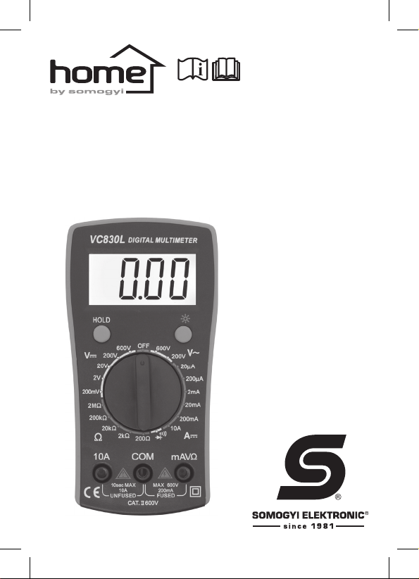
Somogyi VC 830L User manual

VC 830L
instruction manual
eredeti használati utasítás
návod na použitie
manual de utilizare
uputstvo za upotrebu

2
- Front panel
Selector knob: Can be used to select functions, the desired measurement
range, and to turn off/on the unit. Power off – OFF
COM:This is where the black probe cable should be connected.
mAVΩ: This is where the red probe cable (positive) should be connected for
measuring volt age, resistance, diode testing, interruption testing, and
current (max. 200 mA).
10 A: This is where the probe cable should be connected for measuring 0.2
– 10 A DC.
HOLD: Pressing this button will store the reading ap pearing on the display
while an “H” symbol will appear alongside it. Pressing the button again
will cause the instrument to clear the data and the symbol to disappear.
Pressing this button will turn on the backlight for a few seconds.
- Előlap
Forgókapcsoló: kiválaszthatja a funkciókat, a kívánt mérési tartományt, vala-
mint ki/be kapcsolhatja a készüléket. Kikapcsolt állapot-OFF
COM: ide csatlakoztassa a fekete mérőzsinórt
mAVΩ: ide csatlakoztassa a piros mérőzsinórt feszültség, ellenállás, dióda-
vizsgálat, szakadásvizsgálat és áram (max. 200 mA) méréséhez
10 A: ide csatlakoztassa a mérőzsinórt 0,2- 10 A-es egyenáram méréséhez
HOLD: a gomb megnyomásával a kijelzőn megjelenő mérési eredményt rög-
zítheti, közben megjelenik egy „H” szimbólum a kijelzőn. A gomb újbóli
megnyomására az adat törlődik, a szimbólum eltűnik
gombnyomásra a háttérvilágítás néhány másodpercre bekapcsol
- Predný panel
Otočný spínač: zmena funkcie, rozsahu merania, vy/zapnutie prístroja.
Vypnutý stav-OFF
COM: prípojka pre čierny merací hrot
mAVΩ: prípojka pre červený merací hrot pri meraní napätia, odporu,
testovanie diódy a prerušenia, prúdu (max. 200 mA)
10 A: prípojka pre merací hrot na meranie jednosmerného 0,2- 10 A prúdu
HOLD: stlačením tlačidla uloží na displeji nameranú hodnotu, objaví sa
symbol „H”. Jeho ďalším stlačením sa údaj vymaže
stlačením zapnete na pár sekúnd podsvietenie

3
- Panoul frontal
Comutatorul rotativ: Serveşte la pornirea/oprirea multimetrului, precum şi
la selectarea funcţiilor şi a domeniilor de măsurare
dorite. Decuplarea instrumentului se face prin aducerea
comutatorului în poziţia „OFF”.
COM: borna de intrare aferentă cablului de măsurare de culoare neagră
mAVΩ: borna de intrare aferentă cablului de măsurare de culoare roşie,
destinată măsurării tensiunii, rezistenţei/rezistoarelor şi curenţilor
electrici (cu intensitatea maximă de 200 mA), precum şi vericării
diodelor sau testării continuităţii circuitelor
10 A: borna de intrare pentru măsurarea curenţilor continui cu intensitatea
cuprinsă în intervalul de valori 200 mA – 10 A
HOLD: La apăsarea acestui buton, pe aşaj se va memora valoarea măsurată
şi va apărea simbolul „H”. O nouă apăsarea a butonului va determina
ştergerea datei memorate şi dispariţia simbolului.
La apăsarea acestui buton, se va activa pentru câteva secunde
iluminarea de fundal a aşajului.
- Prednja ploča
Obrtni prekidač: Odabir funkcije i mernog opsega, za isključenje i uključenje
instrumenta. Isključeni položaj -OFF
COM: u ovu utičnicu treba priključiti crni merni kabel
mAVΩ: u ovu utičnicu treba priključiti crveni merni kabel za merenje napona,
otpora, diode, prekida is struje (maks. 200 mA)
10 A: u ovu utičnicu treba priključiti crveni merni kabel prilikom merenja
jednosmerne struje 0,2- 10 A
HOLD: Ovim tasterom se može sačuvati merena vrednost na displeju.
Ponovnim pritiskom tastera ili promenom funkcije briše se podatak.
Na displeju se pojavljulje ispis „H”.
pritiskom tastera aktivira se po zadinsko osvetljenje koje radi nekoliko
sekundi

4
DIGITAL MULTIMETER
!
Warning! These operating instructions contain the
information and warnings required for the safe use
and maintenance of the unit. Read and understand the
instructions for use before using the device. Failure to
understand the instructions or observe the warnings can
result in serious personal injury or property damage.
Safety Markings
!
Important warning Read the contents of the
instruction manual.
Dangerous voltage can be present
Grounding
Double insulated (Contact protection class II)
During Use
• If the unit is used near strong electromagnetic
interference, please note that the multimeter’s operation
can become unstable or it may indicate malfunction.
• Never exceed the safety limits specied in the
instructions for each measurement range.
• When the multimeter is connected to a circuit, avoid
contacting it with extraneous devices.
• Do not use the multimeter in situations where the
voltage can exceed 600 V.

5
• If the measurement limits are unknown, please set the
limit selection switch to the highest position.
• Before turning the limit selection switch, disconnect
the probe cable from the measurement circuit.
• When performing measurements on TV sets or circuits
with high AC, always remember that there might be
high amplitude voltage on the test points, which can
damage the multimeter.
• If the voltage to be tested exceeds the effective value
of 60 V DC or 30 V AC, work carefully in order to avoid
sustaining an electric shock.
• Do not use the multimeter in the presence of ammable
gas, vapours or dust.
• Before each use, check the unit in order to ensure pro-
per operation (e.g., using a known voltage source).
General description
Thismeasuring instrumentfeatures a3½ digit,7-segment
display, which is 19.5 mm tall for better legibility. It can be
used to measure direct current, DC voltage, AC voltage,
resistance, diodes and interruption. The reading can be
saved on the display, which is backlit.
Specication
Accuracy is ensured for one year after calibration,
provided the unit is stored at a temperature of 18-28 °C
and a max. relative humidity of 75%.

6
DC voltage measurement ( V)
Connect the red probe cable to the “mAVΩ” socket, and
the black one to the “COM” socket. Set the dial to the
desired position. Connect the measurement probes to
the circuit to be measured. If the value to be measured
is unknown, set the dial to the highest measurement
range then reduce the range according to the reading
until correct. Read the voltage value from the LCD
display. If the probe cables have been connected with
reverse polarity, “-” is displayed in front of the reading.
Measurement limit Resolution Accuracy
200 mV 100 µV
±(0.5% offset ± 4 digits)
2 V 1 mV
20 V 10 mV
200 V 100 mV
600 V 1 V ±(1% offset ± 5 digits)
Input resistance: 1 MΩ
DC measurement
Connect the red probe cable to the “mAVΩ” socket, and
the black one to the “COM” socket. (for measurements
between 0.2 mA and 10A, plug the red probe cable into
the “10A” socket) Set the dial to the desired position.
Interrupt the circuit whose current is to be measured
then connect the probe to the points to be measured.
If the value to be measured is unknown, set the dial to

7
the highest measurement range then reduce the range
according to the reading until correct. Read the value,
including the polarity, from the LCD display.
Measurement limit Resolution Accuracy
20 µA 10 nA
±(1.5% offset ± 3 digits)
200 µA 100 nA
2 mA 1 µA
20 mA 10 µA
200 mA 100 µA
10 A 10 mA ±(2% offset ± 5 digits)
Over-current protection:
“mAVΩ” socket: F 200 mA / 250 V fuse
“10A” socket: without fuse
Measurement of AC voltage (~V)
Connect the red probe cable to the “mAVΩ” socket,
and the black one to the “COM” socket. Set the dial
to the desired measurement range. Connect the
measurement probe to the circuit to be measured. If
the value to be measured is unknown, set the dial to
the highest measurement range then reduce the range
according to the reading until correct. Read the voltage
value from the display.
Measurement limit Resolution Accuracy
200 V 100 mV ±(1.2 % offset ± 10 digits)
600 V 1 V

8
Input resistance: 1 MΩ
Frequency range: 40 Hz-200 Hz
Diode and interruption testing ( )
Diode testing: Connect the red probe cable to the
“mAVΩ” socket, and the black one to the “COM” socket
(the red probe is for “+” polarity).
Set the dial to the “ ” position.
Connect the red probe cable to diode’s anode, and
the black one to its cathode. The display will show the
diode’s approximate forward voltage. If the connection
is reversed, a “1” will appear in the display.
Interruption testing: Connect the red probe cable to
the “mAVΩ” socket, and the black one to the “COM”
socket. Set the dial to the “ ” position. Connect the
measurement probe to the circuit to be tested. If the
circuit is connected to a power source, switch of the
power source and discharge the capacitors before
starting measurement. Short-circuits (less than 70 ± 20
Ω) will be indicated by the built-in buzzer.
Function Resolution Measuring environment
1 mV Measurement current:
approx. 1 mA
Idle voltage: approx. 3 V
The built-in buzzer will activate
below 70±20 Ω Idle voltage: approx. 3 V
Overload protection: 250 V DC or 250 V AC RMS

9
Resistance measurement (Ω)
Connect the red probe cable to the “mAVΩ” socket,
and the black one to the “COM” socket. (The red probe
cable is “+” polarity). Set the dial to the desired ”Ω”
position. If the value to be measured is unknown, set
the dial to the highest measurement range then reduce
the range according to the reading until correct. Contact
the probe with the source of the resistance then read
the gure off the display. If the resistor to be measured
is connected to a circuit, switch of the power source and
discharge the capacitors before starting measurement.
Note: In the 200 Ω measurement range, short the probe
cables in order to measure the resistance of the cable
then deduct it from the gure actually measured.
Measurement limit Resolution Accuracy
200 Ω 0,1 Ω ±(0.8% offset ± 5 digits)
2 kΩ 1 Ω
±(0.8% offset ± 3 digits)20 kΩ 10 Ω
200 kΩ 100 Ω
2 MΩ 1 kΩ ±(1.0% offset ± 15 digits)
Over-voltage protection: 250 V DC or 250 V AC RMS
Battery and fuse replacement
If the “ ” icon appears on the display, the batteries
require replacing. The fuse only needs to be replaced
rarely due to errors associated with use. Prior top

10
replacing the battery/fuse, turn off the instrument and
unplug the probe cables. For battery replacement, use
a screwdriver to remove the screw from the rear panel,
or both screws for fuse replacement. Replace the fuse/
battery. Observe the correct polarity.
Warning:
Before opening the instrument, make sure that the
probe cables have been removed from the measuring
circuit.
Replace and tighten the screws so that the device
operates in a stable manner during use and accident
hazards are avoided.
Accessories: • Instructions for Use • probe cable • 9 V
(6F22) battery • box
DISPOSAL
Waste equipment must be collected and disposed
separately from household waste because it may
contain components hazardous to the environment
or health. Used or waste equipment may be dropped off
free of charge at the point of sale, or at any distributor
which sells equipment of identical nature and function.
Disposeof productat afacility specializingin thecollection
of electronic waste. By doing so, you will protect the

11
environment as well as the health of others and yourself.
If you have any questions, contact the local waste
management organization. We shall undertake the tasks
pertinent to the manufacturer as prescribed in the relevant
regulations and shall bear any associated costs arising.
DISPOSING OFALKALINEAND RECHARGEABLE
BATTERIES
Batteries, whether alkaline or rechargeable, must not
be handled together with regular household waste. It
is the legal obligation of the product’s user to dispose
of batteries at a nearby collection center or at a retail
shop. This ensures that the batteries are ultimately
neutralized in an environment-friendly way.
Specications
• power supply: 9 V (6F22) battery
• display: LCD, up to 1999 digits
• reading over measurement limit: a number “1” on
display
• polarity indication: “-” is displayed for negative polarity.
• operating temperature: 0 – 40 °C, max. 80% RH
• exhausted battery: “ “ icon appears on the display.
• fuse: F 200 mV / 250 V (quick blow)
• dimensions: 140 × 73 × 30 mm
• weight: approx. 170 g (including battery)

12
DIGITÁLIS MULTIMÉTER
!
Figyelem! A használati utasítás a biztonságos
használathoz és a karbantartáshoz szükséges
információkat és gyelmeztetéseket tartalmazza.
Olvassa el és értelmezze a használati utasítást a
készülék használata előtt. Az utasítások meg nem
értése és a gyelmeztetések be nem tartása súlyos
sérüléseket és károkat okozhat.
Biztonsági jelzések
!
Fontos gyelmeztetés! Olvassa el a használati
utasításban foglaltakat!
Veszélyes feszültség lehet jelen
Földelés
Kettős szigetelés (II. érintésvédelmi osztály)
Használat közben
• Ha a készüléket jelentős elektromágneses
interferencia közelében használja, vegye gyelembe,
hogy multiméter működése instabillá válhat, vagy
hibát jelezhet.
• Soha ne lépje túl a biztonsági határértékeket, melyeket
a használati útmutató mérési intervallumonként
meghatároz.
• Amikor a multiméter mérőáramkörre van kapcsolva,
ne érintse meg idegen eszközzel.

13
• Ne használja a multimétert olyan helyzetekben,
amikor a feszültség túllépheti a 600 V-ot.
• Amikor a mérési értékhatárok nem ismertek, állítsa
a méréshatárváltó-kapcsolót a legnagyobb fokozatú
állásba.
• Mielőtt elfordítaná a méréshatárváltó-kapcsolót, távolítsa
el a mérőzsinórt a mérőáramkörből.
• Amikor méréseket folytat a TV-n vagy váltóáramú
áramkörökön, mindig emlékezzen arra, hogy lehet
magas amplitúdójú átmenőfeszültség a tesztpontokon,
amelyek károsíthatják a multimétert.
• Ha a vizsgálandó feszültség meghaladja 60 V DC
vagy 30 V AC effektív értéket, óvatosan dolgozzon,
hogy elkerülje az áramütést.
• Mérés közben tartsa távol az ujjait a csatlakozó
aljzatoktól.
• Ne használja a multimétert robbanásveszélyes gáz,
gőz vagy por közelében.
• Használat előtt mindig ellenőrizze a készüléket
a megfelelő működés érdekében (pl. ismert
feszültségforrással).
Általános leírás
Ez a mérőműszer 3½ digites 7 szegmenses kijelzővel
készült, amelynek magassága 19,5 mm a könnyebb
olvashatóság kedvéért. Használható egyenáram,

14
egyenfeszültség, váltófeszültség, ellenállás, dióda és
szakadás mérésére. A mért érték rögzíthető a kijelzőn,
és háttérvilágítással rendelkezik.
Specikáció
A pontosság a kalibrációt követő egy évig biztosított,
18 -28°C közötti tárolás esetén max. 75% relatív
páratartalom mellett.
Egyenfeszültség mérése ( V)
Csatlakoztassa a piros mérőzsinórt “mAVΩ” aljzatba, a
feketét a “COM” aljzatba. Állítsa a forgókapcsolót a kívánt
pozícióba. Csatlakoztassa a mérőzsinórokat a mérni
kívánt áramkörhöz. Ha a mérendő érték nem ismert, akkor
állítsa a forgókapcsolót a legmagasabb méréshatárba,
majd a mért értéknek megfelelően csökkentse a helyes
állásig. Olvassa le a feszültség értékét az LC kijelzőről.
Ha fordított polaritással csatlakoztatta a mérőzsinórokat,
akkor a kijelzőn a „-” jel látható a mért érték előtt.
Méréshatár Felbontás Pontosság
200 mV 100 µV
±(0,5% eltérés ± 4 digit)
2 V 1 mV
20 V 10 mV
200 V 100 mV
600 V 1 V ±(1% eltérés ± 5 digit)
bemeneti ellenállás: 1 MΩ

15
Egyenáram mérése
Csatlakoztassa a piros mérőzsinórt a “mAVΩ” aljzatba,
a fekete mérőzsinórt a “COM” aljzatba. (a 0,2 - 10 A
közötti méréseknél helyezze a piros mérőzsinórt a “10
A” aljzatba). Állítsa a forgókapcsolót a kívánt helyzetbe.
Szakítsa meg az áramkört, amelyben áramot kíván mérni,
és csatlakoztassa a mérőzsinórt a mérendő pontokra. Ha
a mérendő érték nem ismert, akkor állítsa a forgókapcsolót
a legmagasabb méréshatárba, majd a mért értéknek
megfelelően csökkentse a helyes állásig. Olvassa le az
LC kijelzőről az eredményt, a polaritással együtt.
Méréshatár Felbontás Pontosság
20 µA 10 nA
±(1,5% eltérés ± 3 digit)
200 µA 100 nA
2 mA 1 µA
20 mA 10 µA
200 mA 100 µA
10 A 10 mA ±(2% eltérés ± 5 digit)
túláram elleni védelem: „mAVΩ” aljzat: F 200 mA / 250
V biztosíték, „10 A” aljzat: biztosíték nélkül
Váltófeszültség mérése (~V)
Csatlakoztassa a piros mérőzsinórt a “mAVΩ” aljzatba, a
feketét pedig a “COM” aljzatba. Állítsa a forgókapcsolót a
kívánt méréshatárba. Csatlakoztassa a mérőzsinórt a mérni
kívánt áramkörre. Ha a mérendő érték nem ismert, akkor

16
állítsa a forgókapcsolót a legmagasabb méréshatárba,
majd a mért értéknek megfelelően csökkentse a helyes
állásig. Olvassa le a feszültség értékét a kijelzőről.
Méréshatár Felbontás Pontosság
200 V 100 mV ±(1,2 % eltérés ± 10 digit)
600 V 1 V
bemeneti ellenállás: 1 MΩ
frekvenciatartomány: 40 Hz -200 Hz
Dióda- és szakadásvizsgálat ( )
Diódavizsgálat: csatlakoztassa a piros mérőzsinórt
a “mAVΩ” aljzatba, a feketét pedig a “COM” aljzatba
(a piros mérőzsinór a “+” polaritású). Kapcsolja a
forgókapcsolót a “ ” helyzetbe. Csatlakoztassa
a piros mérőzsinórt a dióda anódjára, a fekete
mérőzsinórt pedig a katódjára. A kijelzőn körülbelül a
dióda nyitófeszültsége fog megjelenni. Amennyiben a
csatlakozás fordított, a kijelzőn az “1” szám jelenik meg.
Szakadásvizsgálat: csatlakoztassa a piros mérőzsinórt
a “mAVΩ” aljzatba, a feketét pedig a “COM” aljzatba.
Kapcsolja a forgókapcsolót a “ ” helyzetbe. Érintse a
mérőzsinórt a vizsgálandó áramkörre. Ha az áramkör
egy tápegységhez kapcsolódik, akkor kapcsolja ki az
áramforrást, és süsse ki a kondenzátorokat, mielőtt
megkezdené a mérést. A rövidzárra (kevesebb, mint 70
± 20 Ω) a beépített hangjelző jelez.

17
Funkció Felbontás Mérési környezet
1 mV mérőáram: 1 mA körül
üresjárati feszültség: 3 V körül
70±20 Ω alatt a beépített
hangjelző megszólal üresjárati feszültség kb. 3 V
túlterhelés elleni védelem: 250 V DC vagy 250 V AC
RMS
Ellenállás mérése (Ω)
Csatlakoztassa a piros mérőzsinórt a “mAVΩ” aljzatba,
a feketét pedig a “COM” aljzatba. (a piros mérőzsinór
a “+” polaritású). Állítsa a forgókapcsolót a kívánt ”Ω”
helyzetbe. Ha a mérendő érték nem ismert, akkor állítsa
a forgókapcsolót a legmagasabb méréshatárba, majd a
mért értéknek megfelelően csökkentse a helyes állásig.
Tegye a mérőzsinórt a mérendő ellenállás forrásába,
majd olvassa le az eredményt. Ha a mérendő ellenállás
egy áramkörhöz kapcsolódik, akkor kapcsolja ki az
áramforrást és süsse ki a kondenzátorokat, mielőtt
megkezdi a mérést.
Megjegyzés: 200 Ω-os méréshatárnál zárja rövidre a
mérőzsinórokat a vezeték ellenállásának méréséhez,
majd vonja ki a ténylegesen mért értékből.

18
Méréshatár Felbontás Pontosság
200 Ω 0,1 Ω ±(0,8% eltérés ± 5 digit)
2 kΩ 1 Ω
±(0,8% eltérés ± 3 digit)
20 kΩ 10 Ω
200 kΩ 100 Ω
2 MΩ 1 kΩ ±(1,0% eltérés ± 15 digit)
túlfeszültség elleni védelem: 250 V DC vagy 250 V AC
RMS
Elem- és biztosítékcsere
Ha az “ ” ikon megjelenik a kijelzőn, akkor elemcsere
szükséges.Abiztosíték cseréje ritkán válik esedékessé,
a működtetés hibái okozhatják a problémát. Az elem/
biztosíték cseréje előtt kapcsolja ki a műszert, húzza ki
a mérőzsinórokat. Elemcseréhez távolítsa el a csavart
/ biztosítékcseréhez távolítsa el mindkét csavart a
hátlapból. Cserélje ki a biztosítékot/elemet. A megfelelő
elempolaritásra gyeljen.
Figyelmeztetés
Mielőtt az eszközt felnyitná, mindig bizonyosodjon
meg arról, hogy a mérőzsinórokat eltávolította a
mérési körből! Csavarja vissza a csavarokat, hogy
stabilan működjön az eszköz használat közben, ezzel
elháríthatja a balesetveszélyt!

19
Tartozékok: • használati utasítás • mérőzsinór • 9 V-os
elem (6F22) • doboz
ÁRTALMATLANÍTÁS
A hulladékká vált berendezést elkülönítetten
gyűjtse, ne dobja a háztartási hulladékba, mert az a
környezetre vagy az emberi egészségre veszélyes
összetevőket is tartalmazhat! A használt vagy hulladékká
vált berendezés térítésmentesen átadható a forgalmazás
helyén, illetve valamennyi forgalmazónál, amely a
berendezéssel jellegében és funkciójában azonos
berendezést értékesít. Elhelyezheti elektronikai hulladék
átvételére szakosodott hulladékgyűjtő helyen is. Ezzel
Ön védi a környezetet, embertársai és a saját egészségét.
Kérdés esetén keresse a helyi hulladékkezelő
szervezetet. A vonatkozó jogszabályban előírt, a gyártóra
vonatkozó feladatokat vállaljuk, az azokkal kapcsolatban
felmerülő költségeket viseljük. Tájékoztatás a
hulladékkezelésről: www.somogyi.hu.
AZ ELEMEK, AKKUK ÁRTALMATLANÍTÁSA
Az elemeket/akkukat nem szabad a normál
háztartási hulladékkal együtt kezelni. A felhasználó
törvényi kötelezettsége, hogy a használt, lemerült
elemeket/akkukat lakóhelye gyűjtőhelyén, vagy a
kereskedelemben leadja. Így biztosítható, hogy az

20
elemek/akkuk környezetkímélő módon legyenek
ártalmatlanítva.
Műszaki adatok
• tápellátás: 9 V elem (6F22)
• kijelző: LCD, 1999 számig
• mérési tartomány feletti jel: “1” számjegy a kijelzőn
• polaritásjelzés: “-” jel jelenik meg, negatív polaritás
esetén
• működési hőmérséklet: 0 – 40°C, max. 80 % relatív
páratartalom
• lemerült telep: “ ” ikon jelenik meg a kijelzőn
• biztosíték: F 200 mV / 250 V (gyors)
• méret: 140 × 73 × 30 mm
• súly: kb. 170 g (elemmel)
DIGITÁLINY MULTIMÉTER
!
Pozor! Návod na použitie obsahuje dôležité
informácie a upozornenia pre bezpečné používanie a
údržbu prístroja. Pred uvedením prístroja do prevádzky
si prečítajte celý návod na použitie. Nepochopenie
pokynov a nedodržanie upozornení môže mať za
následok vážne zranenie alebo poškodenie.
Other manuals for VC 830L
1
Table of contents
Languages:
Other Somogyi Multimeter manuals