Sonardyne 8315 iWAND User manual

Sonardyne International Limited
Blackbushe Business Park
Yateley, Hampshire
GU46 6GD United Kingdom
920-0105
T. +44 (0) 1252 872288
F. +44 (0) 1252 876100
E. support@sonardyne.com
W. www.sonardyne.com
UM-8315
User Manual for the
Type 8315 iWAND
Issue B Rev 1
Date of Issue: 27 May 2014

User Manual for the Type 8315 iWAND UM-8315
Issue B Rev 1
27 May 2014 ii
Sonardyne International Limited 2014. All rights reserved.
Protected by UK patent no. 2415113, US patent no. 8,139,442, and other patents internationally.
6G and Sonardyne Wideband are UK registered trademarks of Sonardyne International Limited.
All rights reserved. No part of this document shall be reproduced, stored in a retrieval system or
transmitted by any means, electronic, mechanical, photocopying, recording, or otherwise, or
translated into any language without the written permission of Sonardyne International Limited.

User Manual for the Type 8315 iWAND UM-8315
Issue B Rev 1
27 May 2014 iii
Contacting the Sonardyne Support Team
24-hour Emergency Telephone Helpline: +44 (0) 1252 877600
The Sonardyne 24-hour helpline is answered at the UK Headquarters during normal office hours
(08:00 to 17:00). Outside these hours, your call is automatically transferred to an agency, which logs
the details of your emergency and alerts the appropriate Sonardyne personnel.
Our aim is to make sure emergency requests are dealt with immediately during office hours, and are
responded to within 30 minutes at all other times.
Please note the helpline is for emergency use only.
If you require NON-EMERGENCY product support, please contact your nearest Sonardyne office.
Alternatively, contact the Sonardyne Head Office:
Sonardyne International Ltd
Blackbushe Business Park
Yateley
Hampshire
GU46 6GD
United Kingdom
Telephone: +44 (0) 1252 872288
Fax: +44 (0) 1252 876100
Email: [email protected]
NOTE
Email and telephone support is available during normal UK office hours (08:00 to 17:00).

User Manual for the Type 8315 iWAND UM-8315
Issue B Rev 1
27 May 2014 iv
Contents
Section 1 Introduction .................................................................................................................. 1
1.1 Scope of this Manual ............................................................................................................. 1
1.2 Purpose of this Manual .......................................................................................................... 1
1.3 Related Publications .............................................................................................................. 1
1.4 Conventions........................................................................................................................... 1
Section 2 – Safety ......................................................................................................................... 2
2.1 Introduction............................................................................................................................ 2
Section 3 – Technical Description ............................................................................................... 3
3.1 Introduction............................................................................................................................ 3
3.2 Hardware Description ............................................................................................................ 3
3.2.1 Battery and Charging ............................................................................................... 3
3.2.2 Communications ...................................................................................................... 4
3.2.3 User Interface .......................................................................................................... 4
3.2.4 Transducer Connector ............................................................................................. 6
3.2.5 USB Connector ........................................................................................................ 6
3.2.6 9-way ‘D’ connector.................................................................................................. 6
3.2.7 End-cap Connector Cover........................................................................................ 7
3.2.8 GPS ......................................................................................................................... 7
3.2.9 Power Modes ........................................................................................................... 7
Section 4 – Connection to the iWAND......................................................................................... 9
4.1 Introduction............................................................................................................................ 9
4.2 Charging the iWAND ............................................................................................................. 9
4.3 Setting the iWAND Time ........................................................................................................ 9
4.4 Connecting to the iWAND .................................................................................................... 10
4.4.1 Bluetooth................................................................................................................ 10
4.4.2 USB ....................................................................................................................... 16
4.4.3 RS232/RS485 Connection ..................................................................................... 20
4.5 iWAND Setup ...................................................................................................................... 21
4.5.1 iWAND Information ................................................................................................ 21
4.5.2 Time Information .................................................................................................... 22
4.5.3 Communications .................................................................................................... 22
4.5.4 User Interface ........................................................................................................ 22
4.5.5 Power Saving......................................................................................................... 24
4.5.6 Discovery Options.................................................................................................. 25
4.5.7 ABOP Mode ........................................................................................................... 27
4.5.8 Transponder Mode................................................................................................. 28
4.5.9 Accessories............................................................................................................ 29
Section 5 – iWAND Operation .................................................................................................... 31
5.1 Introduction.......................................................................................................................... 31
5.2 Menu System....................................................................................................................... 31

User Manual for the Type 8315 iWAND UM-8315
Issue B Rev 1
27 May 2014 v
5.3 Prerequisites for Operation .................................................................................................. 31
5.4 Ping Check .......................................................................................................................... 32
5.5 Quick Check ........................................................................................................................ 34
5.5.1 Acoustic Settings ................................................................................................... 35
5.5.2 Battery Status ........................................................................................................ 35
5.5.3 Firmware Information ............................................................................................. 36
5.5.4 View Sensors ......................................................................................................... 36
5.5.5 Lodestar Support ................................................................................................... 38
5.5.6 Acoustic Check ...................................................................................................... 41
5.5.7 Test Release.......................................................................................................... 43
5.5.8 Acoustic Terminal .................................................................................................. 44
5.6 Get and Set Configuration ................................................................................................... 44
5.7 Get Configuration................................................................................................................. 45
5.7.1 Release Test.......................................................................................................... 48
5.7.2 Sensors Check....................................................................................................... 50
5.8 Set Configuration................................................................................................................. 50
5.9 Tone Testing........................................................................................................................ 54
5.9.1 Sonardyne WSM6.................................................................................................. 54
Section 6 – Maintenance ............................................................................................................ 58
6.1 Introduction.......................................................................................................................... 58
6.2 Scheduled Maintenance and Recalibration.......................................................................... 58
6.3 General Maintenance .......................................................................................................... 58
Section 7 – Functional Test........................................................................................................ 59
7.1 Running Self-Test................................................................................................................ 59
7.2 Running an External Unit Test ............................................................................................. 59
Section 8 – Firmware Upgrade................................................................................................... 60
8.1 Introduction.......................................................................................................................... 60
8.2 Firmware Upgrade Procedure.............................................................................................. 60
Section 9 – Fault Diagnosis ....................................................................................................... 68
9.1 General Operation ............................................................................................................... 68
9.1.1 Unit Does Not Power On When a Key is Pressed on the Keypad........................... 68
9.1.2 Unit Not Responsive .............................................................................................. 68
9.2 PC Communications ............................................................................................................ 68
9.2.1 Bluetooth not Functional on Windows XP............................................................... 68
9.2.2 USB not Communicating ........................................................................................ 68
9.2.3 Acoustic Communications ...................................................................................... 68
Section 10 – Storage................................................................................................................... 69
10.1 Storing the iWAND............................................................................................................... 69
Section 11 – Technical Specifications....................................................................................... 70
11.1 Technical Specification for the iWAND................................................................................. 70
11.1.1 External Power....................................................................................................... 70
11.1.2 Battery Type........................................................................................................... 70

User Manual for the Type 8315 iWAND UM-8315
Issue B Rev 1
27 May 2014 vi
11.1.3 Battery Life............................................................................................................. 70
11.1.4 Environmental ........................................................................................................ 70
11.1.5 Firmware Requirements......................................................................................... 71
Appendix A – Firmware History record ..................................................................................... 72
A.1 Firmware History Record ..................................................................................................... 72
Appendix B – Software Copyright / License / Warranty ........................................................... 73
Appendix C – Windows 8 Driver Installation............................................................................. 75
C.1 USB Driver Installation on Windows 8.................................................................................. 75
Figures
Figure 3-1 – 8315 iWAND............................................................................................................... 3
Figure 3-2 – Example LCD Display Screen..................................................................................... 4
Figure 3-3 – Scrolling Displays ....................................................................................................... 5
Figure 3-4 – Keypad ....................................................................................................................... 5
Figure 4-1 – Mini USB Connection Point for Charging .................................................................... 9
Figure 4-2 – GPS Enabled Receiving a Signal................................................................................ 9
Figure 4-3 – GPS Enabled / Disabled ........................................................................................... 10
Figure 4-4 – Enabling Bluetooth.................................................................................................... 11
Figure 4-5 – USB Bluetooth Dongle CDROM Installation Menu .................................................... 11
Figure 4-6 – Windows 7 Control Panel.......................................................................................... 12
Figure 4-7 – ‘Add a device' ........................................................................................................... 12
Figure 4-8 – Bluetooth Device Added ........................................................................................... 13
Figure 4-9 – Windows 7 Control Panel.......................................................................................... 13
Figure 4-10 – Devices and Printers............................................................................................... 14
Figure 4-11 – Devices and Printers............................................................................................... 14
Figure 4-12 – iWAND Bluetooth Port Properties ........................................................................... 15
Figure 4-13 – Bluetooth Services .................................................................................................. 15
Figure 4-14 – HyperTerminal Over Bluetooth................................................................................ 16
Figure 4-15 – Starting Device Manager......................................................................................... 16
Figure 4-16 – iWAND Driver Installation........................................................................................ 17
Figure 4-17 – USB Update Driver Prompt ..................................................................................... 17
Figure 4-18 – USB Driver Location ............................................................................................... 18
Figure 4-19 – Windows Security Warning ..................................................................................... 18
Figure 4-20 – USB Driver Installation Complete............................................................................ 19
Figure 4-21 – Identifying Assigned iWAND COM Port Number ..................................................... 19
Figure 4-22 – HyperTerminal Connection over USB ..................................................................... 20
Figure 4-23 – Serial Channel Selection......................................................................................... 20

User Manual for the Type 8315 iWAND UM-8315
Issue B Rev 1
27 May 2014 vii
Figure 4-24 – Break Key on Keyboard .......................................................................................... 21
Figure 4-25 – iWAND Serial Output After a <BREAK>.................................................................. 21
Figure 4-26 – iWAND Information ................................................................................................. 21
Figure 4-27 – Time Information View ............................................................................................ 22
Figure 4-28 – Colour Scheme – Standard..................................................................................... 23
Figure 4-29 – Colour Scheme – Green ......................................................................................... 23
Figure 4-30 – Colour Scheme – Orange ....................................................................................... 23
Figure 4-31 – Screen Power On Time Options.............................................................................. 24
Figure 4-32 – GPS Enable / Disable ............................................................................................. 24
Figure 4-33 – Power On Time Before Entering Sleep Mode.......................................................... 25
Figure 4-34 – LMF, MF and HMF Bands....................................................................................... 26
Figure 4-35 – Acoustic Bands ....................................................................................................... 26
Figure 4-36 – Sync Pin Options .................................................................................................... 27
Figure 4-37 – ABOP Mode Selection ............................................................................................ 28
Figure 4-38 – Quick Check with ABOP Mode enabled.................................................................. 28
Figure 4-39 – Transponder Mode.................................................................................................. 28
Figure 4-40 – Serial Terminal Startup View................................................................................... 29
Figure 4-41 – Serial Terminal Command Response View............................................................. 29
Figure 4-42 – GPS Status View .................................................................................................... 30
Figure 4-43 – Current Position View ............................................................................................. 30
Figure 5-1 – Home Screen............................................................................................................ 31
Figure 5-2 – Positioning the iWAND Against the Instrument Transducer....................................... 32
Figure 5-3 – Ping Check Screen ................................................................................................... 32
Figure 5-4 – Ping Check Discovering............................................................................................ 33
Figure 5-5 – Ping Check Interrogating .......................................................................................... 33
Figure 5-6 – Ping Check Result View............................................................................................ 33
Figure 5-7– Quick Check Screen .................................................................................................. 34
Figure 5-8 – Discovering Process Screen..................................................................................... 34
Figure 5-9 – Quick Check Menu ................................................................................................... 35
Figure 5-10 – Instrument Interrogation.......................................................................................... 35
Figure 5-11 – Acoustic Settings View............................................................................................ 35
Figure 5-12 – Battery Status View................................................................................................. 36
Figure 5-13 – Firmware Information View ..................................................................................... 36
Figure 5-14 – View Sensors Menu ................................................................................................ 36
Figure 5-15 – All Sensors View..................................................................................................... 37
Figure 5-16 – Individual Sensor Channel View ............................................................................. 37

User Manual for the Type 8315 iWAND UM-8315
Issue B Rev 1
27 May 2014 viii
Figure 5-17 – Test Sonsors Menu with Lodestar Present.............................................................. 38
Figure 5-18 – Lodestar ON interrogation....................................................................................... 38
Figure 5-19 – Lodestar ON Completion ........................................................................................ 38
Figure 5-20 – Latitude Configuration option for Lodestar .............................................................. 39
Figure 5-21 – Waiting for GPS Fix ................................................................................................ 39
Figure 5-22 – Ready to Acoustically Configure ............................................................................. 40
Figure 5-23 – Latitude configuration sequence ............................................................................. 40
Figure 5-24 – Latitude Configuration Complete............................................................................. 41
Figure 5-25 – Acoustic Check View .............................................................................................. 41
Figure 5-26 – HPR Channel Configured with the iWAND 6G Configurator Software..................... 42
Figure 5-27 – Configuring to HPR Channel................................................................................... 42
Figure 5-28 – Response Detected from the HPR Interrogation ..................................................... 42
Figure 5-29 – Select the current state of the release..................................................................... 43
Figure 5-30 – Select the State for the Drive Motor to Drive to ....................................................... 43
Figure 5-31 – Completed Release State operation ....................................................................... 43
Figure 5-32 – Acoustic Terminal Test Menu.................................................................................. 44
Figure 5-33 – Acoustic Terminal Response Display...................................................................... 44
Figure 5-34 – Get Configuration.................................................................................................... 45
Figure 5-35 – Hold the iWAND Against the Instrument ................................................................. 45
Figure 5-36 – Start of the Get Configuration Process.................................................................... 46
Figure 5-37 – Get Configuration Sequence Discovering ............................................................... 46
Figure 5-38– Get Configuration Sequence Found......................................................................... 46
Figure 5-39 – Get Configuration Sequence Confirm ..................................................................... 47
Figure 5-40 – Sensor Test Request .............................................................................................. 47
Figure 5-41 – All Sensors View..................................................................................................... 47
Figure 5-42 – Get Configuration Sequence Success .................................................................... 48
Figure 5-43 – Testing the Release – Current State ....................................................................... 48
Figure 5-44 – Testing the Release – Activating............................................................................. 48
Figure 5-45 – Testing the Release – State Following Activation.................................................... 49
Figure 5-46 – Testing the Release – Confirm Release Operation ................................................. 49
Figure 5-47 – Option to Test Sensors ........................................................................................... 50
Figure 5-48 – Set Configuration .................................................................................................... 50
Figure 5-49 – Hold the iWAND Against the Instrument ................................................................. 51
Figure 5-50 – Start the Set Configuration Process ........................................................................ 51
Figure 5-51 – Get Configuration Sequence Discovering ............................................................... 51
Figure 5-52 – Get Configuration Sequence Found........................................................................ 52

User Manual for the Type 8315 iWAND UM-8315
Issue B Rev 1
27 May 2014 ix
Figure 5-53 – Get Configuration Sequence Confirm ..................................................................... 52
Figure 5-54 – Sensor Test Request .............................................................................................. 52
Figure 5-55 – All Sensors View..................................................................................................... 53
Figure 5-56 – Set Configuration Sequence Success..................................................................... 53
Figure 5-57 – Configuration Process Aborted ............................................................................... 53
Figure 5-58 – Selecting correct mode for WSM6........................................................................... 54
Figure 5-59 – Interrogation Channel Selection.............................................................................. 54
Figure 5-60 – Wideband Reply Address Selection ........................................................................ 55
Figure 5-61 – Wideband Test........................................................................................................ 55
Figure 5-62 – Test Transmitting State........................................................................................... 56
Figure 5-63 – Nothing Received from Transponder ...................................................................... 56
Figure 5-64 – Response Received................................................................................................ 56
Figure 5-65 – Sonardyne Tone Mode ........................................................................................... 57
Figure 5-66 – HPR400 Mode ........................................................................................................ 57
Figure 8-1 – 6G Terminal Lite Icon................................................................................................ 60
Figure 8-2 – 6G Terminal Lite Dialog Box/6G Setup Tab .............................................................. 61
Figure 8-3 – About 6G Terminal Lite ............................................................................................. 61
Figure 8-4 – 6G Setup Tab/Connect ............................................................................................. 61
Figure 8-5 – Select COM Port....................................................................................................... 62
Figure 8-6 – Select Port/Connect.................................................................................................. 62
Figure 8-7 – Current iWAND Configuration ................................................................................... 63
Figure 8-8 – Bootloader Selection................................................................................................. 63
Figure 8-9 – Bootloader Firmware List .......................................................................................... 64
Figure 8-10 – Select Download Application................................................................................... 64
Figure 8-11 – Confirm Replace Firmware ..................................................................................... 65
Figure 8-12 – Select New Firmware File ....................................................................................... 65
Figure 8-13 – Downloading New Firmware ................................................................................... 66
Figure 8-14 – Download Completed.............................................................................................. 66
Figure 8-15 – Close Bootloader .................................................................................................... 67
Figure 8-16 – Refresh 6G Terminal Lite Settings .......................................................................... 67
Tables
Table 1-1 – Related Publications .................................................................................................... 1
Table 3-1 – 9-way D Connector Connections.................................................................................. 6
Table 3-2 – iWAND Power Modes .................................................................................................. 7
Table A-1– Firmware History Record ............................................................................................ 72

User Manual for the Type 8315 iWAND UM-8315
Issue B Rev 1
27 May 2014 x
Amendment History
The amendment history records all amendments and additions made to this manual.
Issue Revision Date Comments Section Page
A 0 07/03/13 Initial Issue All All
B 0 21/06/13 ECN12223 Inclusion of Firmware
Upgrade instructions. 8 54
B 1 27/05/2014 ECN12598:
ABOP Mode added
Lodestar Configuration added
Windows 8 Driver Installation added
Updated Section 1
Formatting and minor text updates
4.5.7
5.5.5
App C
1
All
27-29
38-41
75-77
1
All

User Manual for the Type 8315 iWAND UM-8315
Issue B Rev 1
Section 1
27 May 2014 1
Section 1 Introduction
1.1 Scope of this Manual
This User Manual describes the safe installation, operation and maintenance of the 8315 iWAND.
The information and procedures within this manual are based on Sonardyne’s experience and
knowledge.
To make sure the safety of the installer and operator is maintained it is important that all Warnings,
Cautions and Safety Section in this manual, and the Warnings, Cautions and Safety Section of any
additional manuals are read and understood.
1.2 Purpose of this Manual
This user manual contains information for personnel involved in installing, operating and
maintaining the iWand.
1.3 Related Publications
To make sure the system is operated safely, a Safety Manual is supplied with this User Manual. It
is important the Safety Manual is read and understood before proceeding with any activity on the
equipment.
The related publications are:
Table 1-1 – Related Publications
Publication Title
Safety Manual Safety Manual
1.4 Conventions
Format Convention
Boldface Type User Input, Menu Options, Keys, References e.g. Click OK
Arrow (>) Selection of an additional menu item e.g. File > Save

User Manual for the Type 8315 iWAND UM-8315
Issue B Rev 1
Section 2
27 May 2014 2
Section 2 – Safety
2.1 Introduction
The 8315 iWAND contains no user serviceable parts. Under no circumstances should the plastic
housing be opened – any repairs are return to base.
It is recommended the operator complies with the Health and Safety Regulations applicable to the
vessel and the region before operating this equipment.
Operators and service personnel must be familiar with the normal operating and safety procedures
for Subsea Equipment.
Documentation must be consulted whenever a Warning symbol is found on the equipment, in
order to determine the nature of the potential hazard and any actions which must be taken.
If the equipment is used in a manner not specified by the manufacturer, the protection provided by
the equipment may be impaired.

User Manual for the Type 8315 iWAND UM-8315
Issue B Rev 1
Section 3
27 May 2014 3
Section 3 – Technical Description
3.1 Introduction
The Type 8315 iWAND (iWAND) is a handheld multiband test unit for acoustic testing and
configuration of Sonardyne 6G equipment. The iWAND utilizes Sonardyne 6G Discovery to identify
the unit under test (UUT) with a simple one-touch operation without knowledge of the acoustic
address or frequency band. The rugged design coupled with simple interface and local colour
display makes the iWAND ideal for back-deck operations.
Using the companion iWAND 6G Configurator software the iWAND simplifies configuration so the
user does not require special knowledge of the Sonardyne 6G configuration language. When
configured the 6G Configurator can generate a formatted report reflecting all settings configured on
a unit prior to deployment. A database is held by the software so a history of all units configured
can be maintained for later review.
The iWAND supports all 6G acoustic frequency bands (LMF, MF and HMF) and address ranges
(Wideband® V1, Wideband® V2 and Wideband® V2 plus).
3.2 Hardware Description
The iWAND contains a low-power transceiver that communicates in the 6G command language.
The rugged enclosure is rated to IP65 and can be operated over the temperature range [-
10..+55]°C making it functional in most environments.
Figure 3-1 – 8315 iWAND
Acoustic Transducer
Five Button Keypad
Status LEDs (Bluetooth and Charging)
Mini USB ‘B’ Connector
Colour LCD Display
9 way RS232/RS485 Connector
3.2.1 Battery and Charging
The iWAND contains an integrated lithium polymer battery. Charging is performed either when the
unit is plugged into a computer via USB interface or via the supplied USB mains power adapter.
The charge indicator LED on the front of the case above the screen indicates the 3 states of
charging:
•OFF – no USB power has been detected
•Orange – the battery is being charged
•Green – the battery charge has completed
User Manual for the Type 8315 iWAND UM-8315
Issue B Rev 1
Section 3
27 May 2014 4
3.2.2 Communications
The iWAND can communicate serially via either RS232, half-duplex RS485, Bluetooth or USB. The
iWAND 6G Configurator software will automatically identify the iWAND and establish a link to it. In
addition to PC communication, the 9-way ‘D’ connector can be used with a standard Compatt data
cable for serial testing. The RS232 connections on the connector are configured as data terminal
equipment (DTE) so a cross-over cable is required to connect to a computer via this interface.
3.2.3 User Interface
The iWAND user interface comprises 3 units:
•a 320x240 pixel sunlight readable LCD display
•a five key push-button keypad and
•a 3-axis accelerometer for orientation detection.
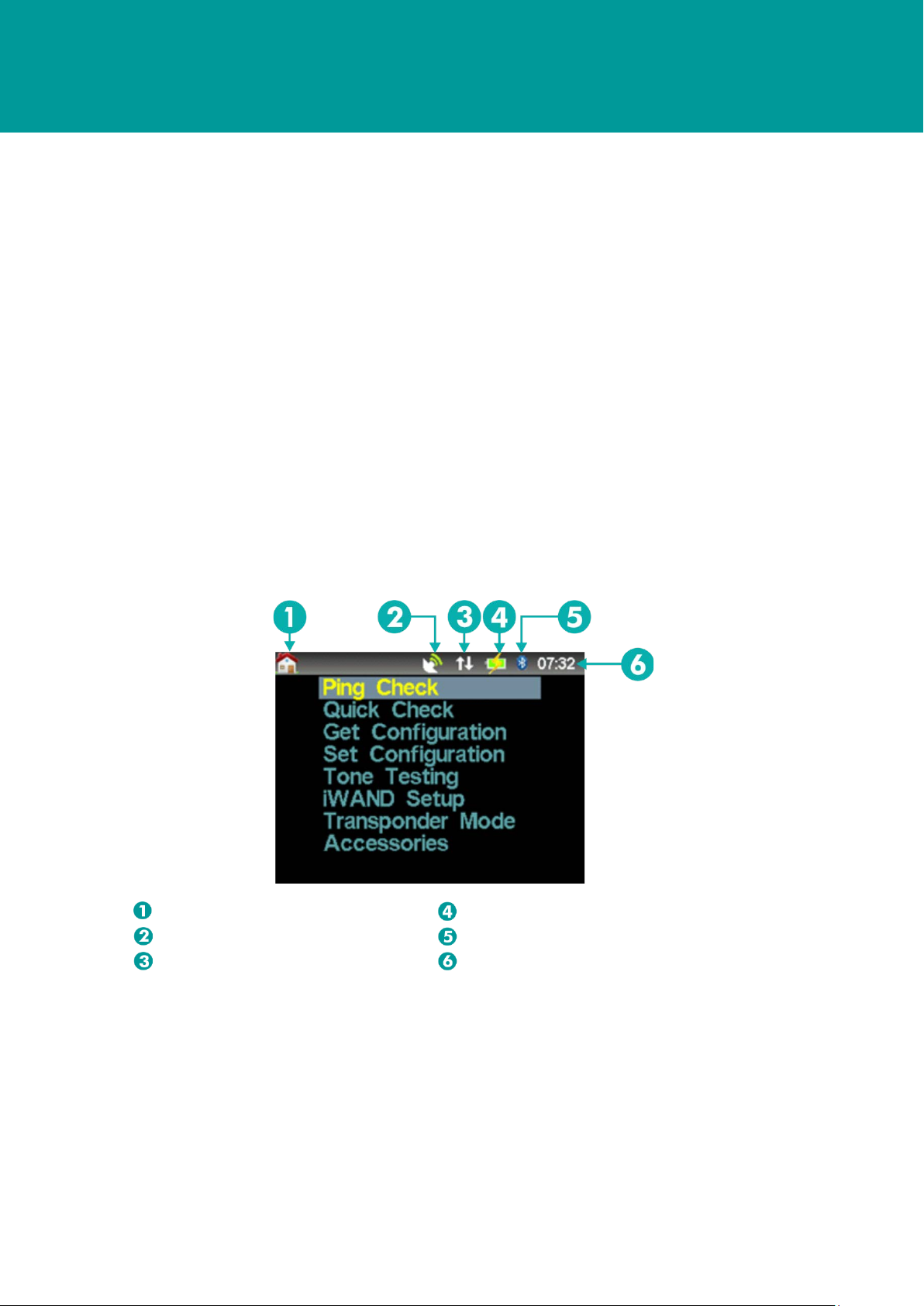
LCD Display
The LCD display provides local feedback of test results and progress of configuration related
operations. It also provides configuration of the iWAND settings. All user interface screens have a
common title bar at the top of the screen to display persistent information.
Figure 3-2 – Example LCD Display Screen
Menu Navigation
Internal Battery Level and Charging State
GPS Status
Serial Communication Method
Serial Communications Status
UTC Time

User Manual for the Type 8315 iWAND UM-8315
Issue B Rev 1
Section 3
27 May 2014 5
For any menus or table displays that are too long to fit on the screen a direction indicator icon is
displayed. The UP and DOWN arrow keys can be used to scroll the display.
Figure 3-3 – Scrolling Displays
Keypad
The five button keypad enables menu navigation and option selection on the iWAND User
Interface. Options are selected with the four outer buttons and the central ENT key is used to make
the selection.
Figure 3-4 – Keypad
Power to the unit can be controlled by the ENT button. Pressing the ENT button for more than 1
second and less than 5 seconds will put the iWAND into IDLE mode (refer to 3.2.9 – Power
Modes). When entering IDLE mode via this method the ‘shake to wake’ function is disabled.
Pressing the ENT for more than 5 seconds will put the iWAND into SLEEP mode.
NOTE
In the event the iWAND becomes unresponsive, pressing the UP and DOWN keys together for
more than 3 seconds resets the unit.
Accelerometer
The accelerometer performs two functions:
•Wakes up the unit from sleep when shaken ‘shake to wake’
•Rotates the screen dependent on the orientation of the unit to make reading easier
When the Shake to Wake mode is disabled a press on any key on the keypad is required to wake
the unit.

User Manual for the Type 8315 iWAND UM-8315
Issue B Rev 1
Section 3
27 May 2014 6
The screen rotation control allows the screen to rotate when the iWAND orientation is changed.
The internal accelerometers are used to detect the orientation of the unit and rotate the screen
accordingly to make the display easier to read.
3.2.4 Transducer Connector
CAUTION
Risk of Corrosion. When the iWAND is not in-use make sure the tethered transducer is
plugged in to reduce the risk of corrosion forming on the BNC connector.
The BNC connector in the top of the enclosure is for attachment of the tethered iWAND transducer
or an external hydrophone. Care should be taken when an external hydrophone is used as the
splash-proofing of the housing will be compromised.
3.2.5 USB Connector
A standard Mini-USB Type ‘B’ connector is mounted at the bottom of the housing. This is for data
communications with a host PC and for charging the unit. The iWAND complies with the USB 2.0
specification. While the unit will charge from a PC USB port, due to the charging requirements of
the iWAND (especially when connected via unpowered hubs) it is recommended to use the
supplied external mains USB adapter for charging.
3.2.6 9-way ‘D’ connector
The 9-way ‘D’ connector carries the following signals:
•RS232
•RS485
•Trigger In / Out
Table 3-1 – 9-way D Connector Connections
Pin # Signal Notes
1 N/C
2 RS232RX / RS485B Receive line into iWAND in RS232 mode
Data B line (Data -) in RS485 mode
3 RS232TX / RS485A Transmit line out from iWAND in RS232 mode
Data A line (Data +) in RS485 mode
4 N/C
5 GND Signal GND
6 N/C
7 RS232 RTS Request to send out from iWAND
8 RS232 CTS Clear to send into iWAND
9 Trigger Software configurable {IN / GPS PPS OUT}

User Manual for the Type 8315 iWAND UM-8315
Issue B Rev 1
Section 3
27 May 2014 7
3.2.7 End-cap Connector Cover
The rubber bung tethered to the end-cap must be fitted whenever the connectors are not in use.
Any internal connector covers should also be fitted. It is critical the connectors are protected as
much as possible for both direct splash and moist air.
3.2.8 GPS
A GPS receiver is built into the iWAND for time synchronization and position recording. The primary
functions of the GPS are:
•Synchronize the iWAND real-time clock with UTC time
•Provide location information when the iWAND is used to either set or get a configuration
from a 6G instrument
•Keep time after the iWAND has powered down
•Provide a 1 PPS trigger out for external unit synchronization
3.2.9 Power Modes
As the iWAND has a limited capacity battery pack, to maximize battery life a number of power
management features have been included in its design. These are outlined below.
Table 3-2 – iWAND Power Modes
Mode Description To wake up
Increasing Battery Life
Normal Active mode – all systems on N/A
Idle Screen switched off – all other systems
active. Fully functional as transceiver
‘Shake to wake’ or keypad
button press
Sleep
Keypad powered for keypress wakeup
and GPS real-time clock maintained. No
longer functional as a transceiver.
Keypad button press
Deep Sleep All systems switched off. Connect USB power
The battery life in each mode is shown in Section 11.1.2 - Battery .
3.2.9.1 Normal Mode
In this mode the screen and all systems are powered, this will result in maximum battery drain. To
increase battery life it is advisable to keep the screen-on time to a minimum.
3.2.9.2 Idle Mode
In this mode the screen is turned off to reduce power consumption. If used as a transceiver the unit
will continue to function normally in this state. The unit can be returned to the normal mode by
pressing any button on the keypad; if inertial wakeup is enabled shaking the unit will have the same
effect. The time the iWAND stays in Normal Mode before entering Idle Mode is user configurable
from between 1 and 30 minutes. The shorter the screen-on time, the longer the battery will last.

User Manual for the Type 8315 iWAND UM-8315
Issue B Rev 1
Section 3
27 May 2014 8
Each time a button is pressed while the screen is on or the orientation of the unit is changed, the
screen-on timer is reset so the screen will stay on for the configured time after this event. The
iWAND can be manually put into Idle Mode by holding the ENT button down for more than 1
second (but less than 5 seconds or the unit will enter Sleep Mode).
3.2.9.3 Sleep Mode
In this mode the main processor is switched off so the unit can no longer respond to serial
commands or communicate acoustically. The only systems that are maintained in this state are the
keypad, so a button press can wake the unit and the real-time clock in the GPS unit so the
processor has an approximate time on power-up. An accurate time will be acquired as soon as the
unit has a view of the sky to get an updated GPS fix.
The iWAND can be manually put into Sleep Mode by holding down the ENT button for more than 5
seconds.
3.2.9.4 Deep Sleep
This mode is the lowest power mode for the iWAND. In this state all systems are powered off so the
GPS will lose its time and the keypad wakeup will not function. The only way to start-up from this
state is by plugging in USB power.
This mode should be used when shipping the unit – it electronically disconnects the battery and the
disabling of the keypad means that it won’t accidently be turned on and arrive with a flat battery.
When leaving this mode the battery level indicator will not be valid until the unit has fully charged.
When leaving the unit on the shelf for extended periods it is advisable to put it in this mode.
User Manual for the Type 8315 iWAND UM-8315
Issue B Rev 1
Section 4
27 May 2014 9
Section 4 – Connection to the iWAND
4.1 Introduction
The iWAND is supplied in a transit case containing all accessories including charging equipment
(with international plug adapters) and Bluetooth dongle. Before operating the iWAND it must first be
fully charged and the UTC time must be set.
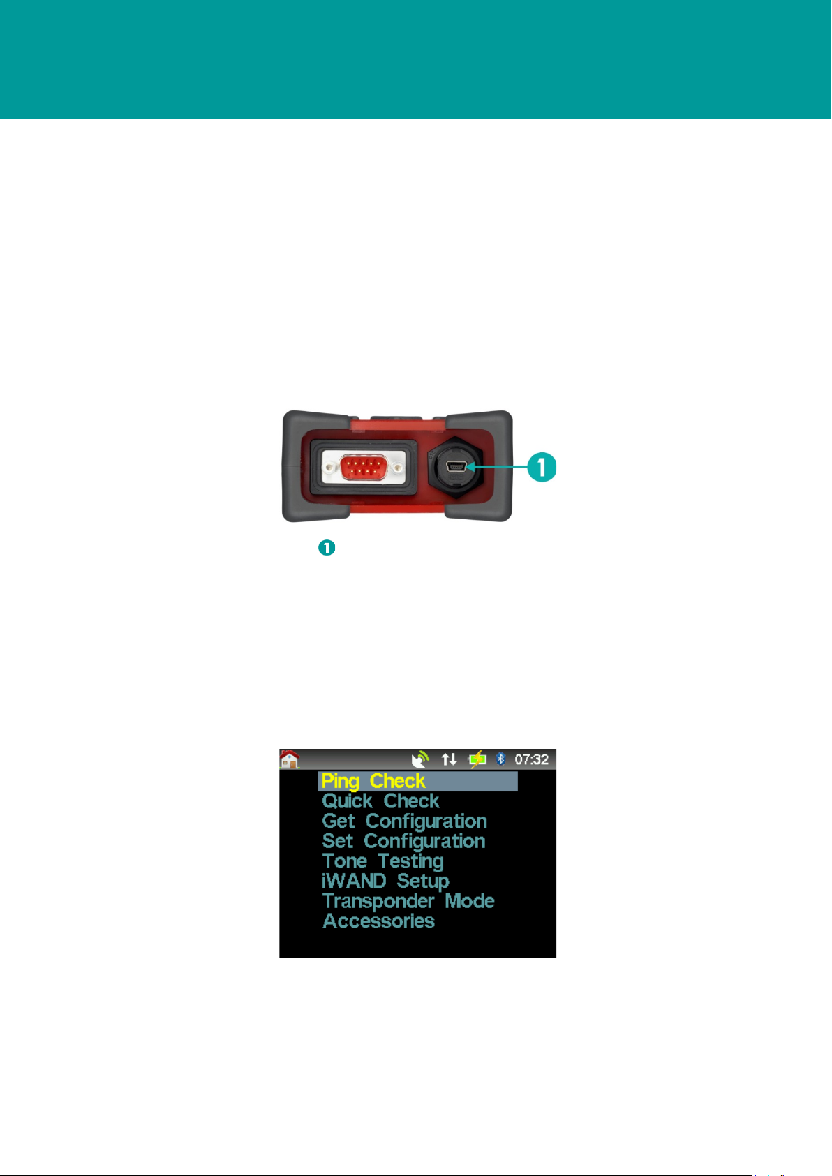
4.2 Charging the iWAND
To charge the iWAND connect the wall plug charger to the mini USB connection point on the
bottom of the iWAND and using one of the international plug adapters connect to a mains power
supply.
Figure 4-1 – Mini USB Connection Point for Charging
Mini USB ‘B’ Connector
The iWAND will be fully charged when the green LED light is illuminated. With the iWAND attached
to the charger, switch the iWAND ON to configure the charge percentage value.
4.3 Setting the iWAND Time
On receipt of the iWAND the UTC time on the unit will need to be set. To set the time the GPS must
be enabled and receiving a signal. A satellite symbol with signal bars will be displayed on toolbar
when the GPS is enabled and receiving a signal.
Figure 4-2 – GPS Enabled Receiving a Signal

User Manual for the Type 8315 iWAND UM-8315
Issue B Rev 1
Section 4
27 May 2014 10
If the GPS symbol is not present it can be enabled by scrolling to the iWAND Setup > Power
Saving > GPS Enable.
Figure 4-3 – GPS Enabled / Disabled
Make sure the iWAND has a clear view of the sky. The satellite symbol will flash to indicate the
internal clock is being set. Wait for the symbol to stop flashing and the UTC time is displayed.
NOTE
The time shown is UTC time and not local time.
4.4 Connecting to the iWAND
There are several ways to connect the iWAND:
•Wirelessly via Bluetooth (Windows 7 or later only recommended)
•USB
•Serially via RS232 or half duplex RS485
Any of these methods can be used to communicate with the iWAND 6G Configurator software, or if
the iWAND is being used as a transceiver. All the connection methods will present themselves to
the computer as a standard COM port so can be used with any terminal program (HyperTerminal,
ProComm etc.).
The RS232/RS485 interface can also be used to connect directly to an instrument for serial
interface testing using the iWAND Serial Terminal from the Accessories menu.
4.4.1 Bluetooth
It is highly recommended the Bluetooth dongle supplied with the iWAND is used to make
connection. If a computer is being used with integrated Bluetooth it is recommended the internal
Bluetooth is disabled and the supplied Bluetooth dongle is used. If this is not possible the computer
Bluetooth interface must be capable of supporting the Bluetooth 2.1+EDR standard or later.
The iWAND Bluetooth interface supports the Bluetooth Serial Port Profile (SPP) so once installed it
will appear as a standard COM port. The Bluetooth radio signal range is dependent on the
environment but should normally operate up to 10 meters from the computer.
Table of contents


