Sonel CMM-60 User manual

USER MANUAL
INDUSTRIAL MULTIMETER
CMM-60
SONEL S.A.
Wokulskiego 11
58-100 Świdnica
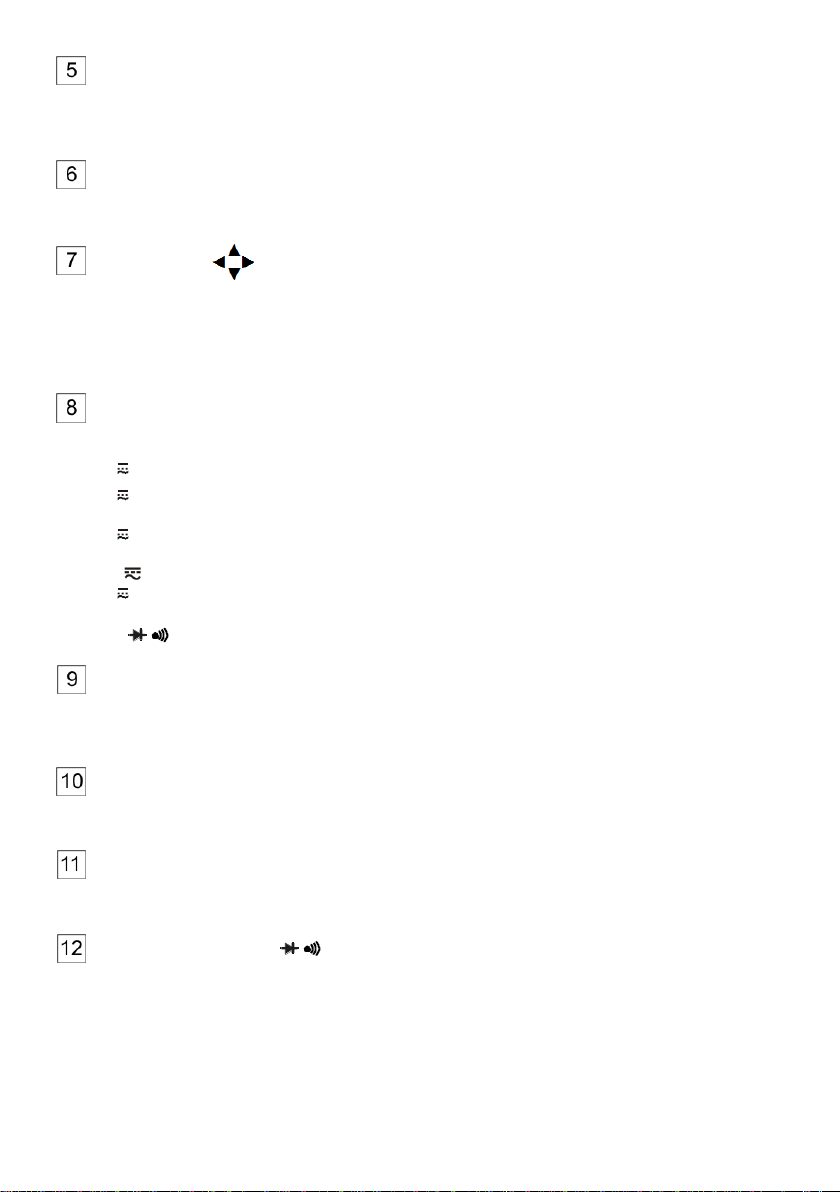
Poland
Version 1.14 19.10.2023

CMM-60 –USER MANUAL
CMM-60 multimeter is intended for measuring direct and alternating voltage, direct and alternating cur-
rent, resistance, capacitance, frequency (in electrical and electronic devices/systems), duty cycle (fill-
ing), temperature and for testing diodes and circuit continuity.
The most important features of CMM-60 include:
large and clear colour display 3.5"
function of data recording with graphical presentation of results,
built-in memory for recording the results,
Bluetooth wireless communication for data transmission,
a low pass filter,
automatic and manual range setting,
HOLD function used to hold the measurement results on the screen,
REL function for relative measurements,
MAX/MIN function for displaying maximum and minimum values,
function of displaying peak values,
sound signal for circuit continuity,
AUTO-OFF function,
two-component housing, waterproof.
CMM-60 –USER MANUAL
1 Introduction
Thank you for purchasing Sonel multimeter. CMM-60 meter is a modern, easy and safe measuring
device. Please acquaint yourself with this manual in order to avoid measuring errors and prevent pos-
sible problems in operation of the meter.
This manual contains two types of warnings. They are presented as a framed text describing the
possible risks for the user and the device. Texts starting with word ‘WARNING’ describe situations,
which may endanger user's life or health, when instructions are not followed. Word ‘CAUTION!’ be-
gins a description of a situation, which may result in device damage, when instructions are not fol-
lowed. Indication of possible problems is preceded by word ‘Note’.
WARNING:
CMM-60 meter is intended for measuring direct and alternating voltage, direct and alternating
current, resistance, capacitance, frequency, duty cycle, temperature and for testing diodes and
circuit continuity. Any application that differs from those specified in the present manual may
result in a damage to the device and constitute a source of danger for the user.
WARNING:
CMM-60 meter must be operated only by appropriately qualified personnel with relevant certifi-
cates authorising the personnel to perform works on electric systems. Unauthorized use of the
meter may result in its damage and may be a source of serious hazard to the user.
WARNING:
Before operating the device, read thoroughly this manual and observe the safety regulations
and guidelines provided by the producer. Failure to follow instructions specified in this manual
may result in a damage to the device and be a source of serious hazard to the user.
2 Safety
2.1 General rules
In order to provide conditions for correct operation and the correctness of the obtained results, the
following recommendations must be observed:
before using the meter read carefully this manual,
the meter should be operated only by qualified persons that have passed health and safety training,
be very careful when measuring voltages exceeding (as per IEC 61010-1:2010/AMD1:2016):
60 V DC,
30 V AC RMS,
42,4 V AC of peak value,
as they generate a potential risk of electric shock,
do not exceed the maximum limits of the input signal,
during the voltage measurements do not switch the device in the current or resistance measuring
mode and vice versa,
when changing ranges (changing the position of the rotary switch) always disconnect the test leads
from the tested circuit,
measuring probes should be kept in the space provided, restricted by a special barrier to avoid acci-
dental contact with exposed metal parts,
if during the measurement OL symbol is displayed, it indicates that the measured value exceeds the
measurement range. Switch to a higher range.
1
CMM-60 –USER MANUAL
it is unacceptable to operate the device when:
a damaged meter which is completely or partially out of order,
a device with damaged insulation of test leads,
a meter stored for an excessive period of time in disadvantageous conditions (e.g. excessive
humidity).
repairs may be carried out only by an authorised service point.
WARNING:
Never start the measurements if you have wet or damp hands.
WARNING:
Do not perform measurements in explosive atmosphere (e.g. in the presence of flammable
gases, vapours, dusts, etc.). Using the meter in such conditions may result in sparking and
cause an explosion.
CAUTION!
The limit values of the input signal
Function
The maximum
input value
V DC or V AC
1000 V DC/AC RMS
mA AC/DC
Quick acting fuse 800 mA 1000 V
A AC/DC
Quick acting fuse 10 A 1000 V
(20 A current max for
30 sec. to 15 minutes)
Frequency, resistance, elec-
trical capacitance, duty cycle,
diode test, continuity
1000 V DC/AC RMS
Temperature
1000 V DC/AC RMS
Surge protection: peak value 8 kV, according to IEC 61010
2.2 Safety symbols
This symbol located near another symbol or terminal, indicates that the user should read the
further information contained in the manual.
This symbol located near the terminal, indicates that in normal use there is a possibility of
dangerous voltages.
Protection class II - double insulation
It is recommended that the terminals with such marking are not connected to the potential
exceeding 1,000 V AC or 1,000 V DC relative to the ground.
2
CMM-60 –USER MANUAL
3 Preparing the meter for operation
After purchasing the meter, check whether the content of the package is complete.
Before performing the measurement:
make sure that the battery level is sufficient for measurements,
make sure that the device has fuse installed and efficient,
check whether the meter casing and insulation of the test leads are not damaged,
to ensure consistent measurement results it is recommended to connect black lead to COM terminal
and red lead to other terminals,
WARNING:
Connecting wrong or damaged leads may cause electric shock.
WARNING:
Do not perform the measurements if the potential of the COM terminal to earth exceeds 1000 V.
WARNING:
The meter must not be connected to the voltage source when it is set to current or resistance
measurement or to diode test. Failure to observe this precaution may damage the meter!
When using the meter, be sure to:
discharge capacitors in the tested power sources,
disconnect the power supply from the tested object when measuring the resistance and diode tests,
turn off the meter and disconnect test leads before removing the back cover to replace the battery or
fuses.
WARNING:
Do not use the meter if the cover of battery and fuse compartment is removed.
Note:
It is possible that in certain low ranges of AC or DC voltage, when the meter is not connected
to the leads, the screen will show random and variable readings. This is a normal phenomenon,
which results from the input sensitivity with high input resistance. When connected to a circuit,
the read-out will stabilize and the meter will provide the correct value.
3
CMM-60 –USER MANUAL
4 Functional description
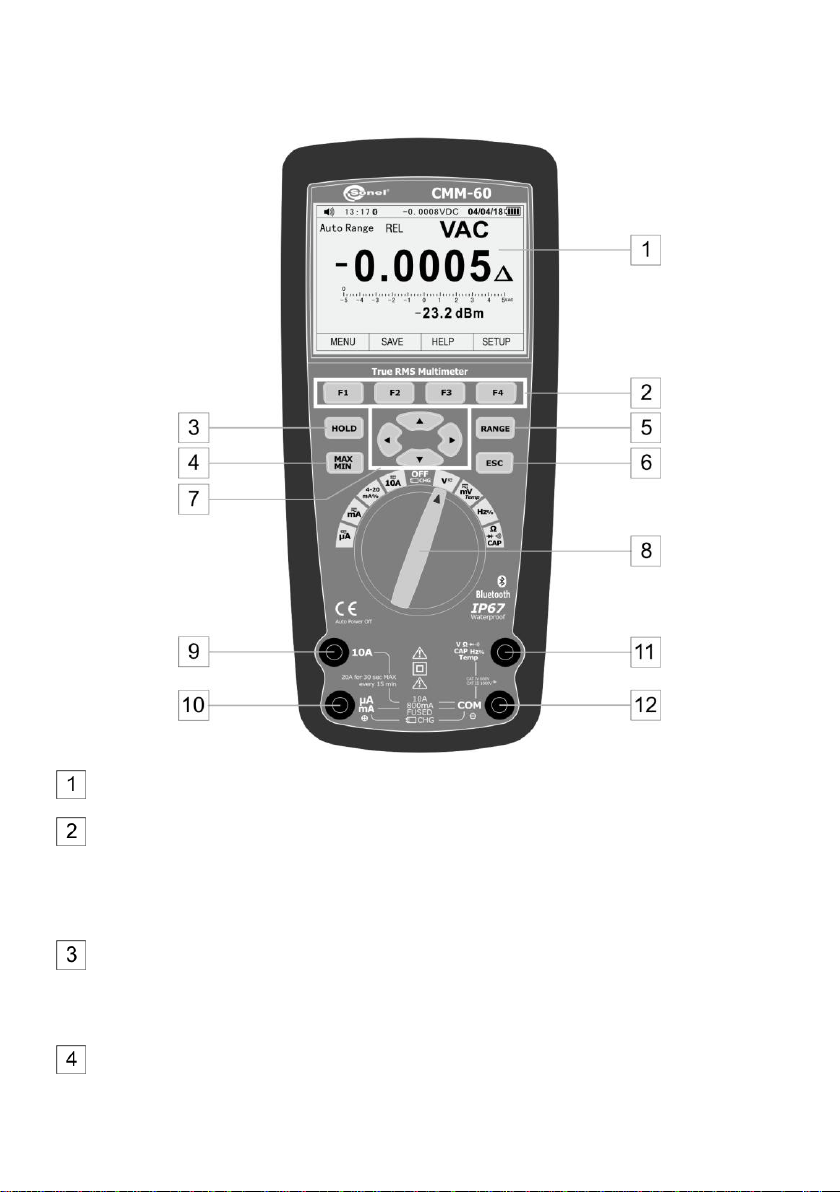
4.1 Measuring terminals and functions
Liquid Crystal Display (LCD)
Function buttons F1 F2 F3 F4
The choice of sub-functions and modes assigned to the selected measurement function
Useful help
Meter Settings
HOLD button
Freezing the measurement results on the display.
Access to AutoHold function
MAX/MIN button
Turns MIN MAX recording on/off
4
CMM-60 –USER MANUAL
RANGE button
Manual change of the measuring range (short press)
Entering the automatic measuring range (press and hold for approx. 2 s)
ESC button
Restoring the last screen before the automatic shutdown of the meter
Arrow buttons
Function selection in menu
Setting the screen contrast
Moving around the screen
Data input
Rotary switch
Function selection:
μA Measurement of AC, DC, AC+DC up to 5,000 μA
mA Measurement of AC, DC, AC+DC
4~20mA% Measurement of current loop 4-20 mA
10A Measurement of AC, DC, AC+DC up to 10 A
OFF/CHG meter off/charging batteries
VMeasurement of AC, DC, AC+DC voltage
mVTemp measurement of AC, DC, AC+DC voltage, temperature
Hz% measurement of frequency, duty cycle
ΩCAP measurement of resistance, diode test, continuity test, capacitance
Measuring terminal 10A
Measuring input for AC and DC measurements, up to 10 A (permissible current of 20 A for 30
seconds).
Measuring terminal µA/mA
Measuring input for AC and DC measurements, up to 500 mA.
Measuring terminal COM
Measuring input, common for all measuring functions.
Measuring terminal V ΩCAP Hz% Temp
Measuring input for measurements other than current measurements.
5

CMM-60 –USER MANUAL
4.2 Display
Functions assigned to physical buttons F1 F2 F3 F4
Analog bar graph
Negative read-out value
Indicator of range selection mode (auto / manual)
Symbol of enabled/disabled sounds
Time
Bluetooth indicator
Meter mode indicator
Meter reading
Continuous overview of meter reading, when HOLD mode is active
Date
Battery charge status
Indicator of measured quantity
Mode indicator REL –reading relative to the reference value
Value of additional measured quantity
6

CMM-60 –USER MANUAL
4.3 Leads
The manufacturer guarantees the correctness of read-outs only when original test leads are used.
WARNING:
Connecting wrong leads may cause electric shock or measurement errors.
Note:
The probes are equipped with additional removable tip guards.
5 First steps
Legend:
F1 F2 F3 F4 –press one of the function buttons
–press one of the arrows
5.1 Auto-Off
F4 (SETUP) ►▼▼(Display) F1 (DISPLAY) ▼▼▼ (Auto Power Off) F1 (EDIT)
Set the desired value ▲▼ F1 (OK)
Details: section 7.7.6
Note: This feature does not work with active wireless communication
5.2 Button tones on/off
F4 (SETUP) ►▼▼(Display) F2 (FORMAT) Beeper F1 (EDIT)
Set the desired value
F1 (ON) –enabled
F2 (OFF) –disabled
Details: section 7.7.6
5.3 Wireless communication
F4 (SETUP) ►▼(Communicate) F1 (ENTER)
Turn on Bluetooth? F1 (OK)
Details: section 7.7.5
7
CMM-60 –USER MANUAL
5.4 MENU panel
F1 (MENU) selection of the measuring mode
F1 F2 F3 F4 selection of measurement parameters
Details: section 7.1
5.5 MAX/MIN function
MAX/MIN button –turn on the function
F4 (STOP) F4 (CLOSE) –turn off the function
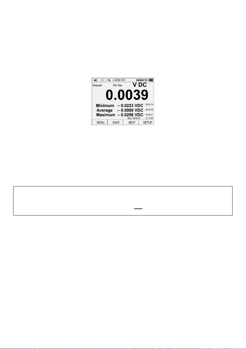
The function displays three values:
Minimum recorded value of the amplitude,
Average of all recorded values,
Maximum recorded value of the amplitude.
Details: section 7.3
Note: when the meter switches off automatically and then it is restarted with ESC button, data
on the screen will be lost.
5.6 HOLD function
HOLD –the upper bar of the display shows the current measured signal
AutoHold –monitors the input signal. Updates stopped read-out, when the meter detects a new sta-
ble value of the signal
HOLD button - on/off
F1 (AUTOHOLD)
F1 (CANCEL) –disable AutoHold
F4 (CLOSE) –enable HOLD/AutoHold
Details: section 7.4
Note: when the meter switches off automatically and then it is restarted with ESC button, data
on the screen will be lost.
5.7 RANGE function
RANGE button enables the manual change of the measurement range.
RANGE –enable the manual change of ranges.
RANGE –switches measurement ranges in the loop
RANGE (hold for 2 s) –disable the function
Details: section 7.5
8

CMM-60 –USER MANUAL
6 Measurements
The content of this chapter should be thoroughly read and understood since it describes methods
of measurements and basic principles of interpreting measurement results.
6.1 Voltage measurement up to 1000 V
WARNING:
Electric shock hazard. The ends of measuring probes, due to their length, may not reach the
live parts inside some network connections of low-voltage electrical equipment, because the
contacts are arranged inside the sockets. In such a case, the read-out will be 0 V with the sim-
ultaneous presence of voltage in the socket.
Before acknowledging the absence of voltage in the socket make sure that the ends of the of
the probe touch the metal contacts inside the socket.
NOTE
Do not measure the voltage when an electric motor located within the circuit is being switched
on or off. Resulting voltage spikes may damage the meter.
6.1.1 Performing the measurement
To perform voltage measurement:
set the rotary switch at V,
select MENU and use arrows and F1 F2 F3 F4 buttons to set the measurement of:
direct current voltage VDC,
alternating current voltage VAC (default setting),
connect black test lead to COM terminal and red test lead to VΩCAP Hz% Temp terminal,
contact the tips of test probes to the points of measurement; red probe should be applied to the
point of higher potential,
read the measurement result on the display,
after completing the measurements, remove test leads from the terminals of the meter.
6.1.2 Voltage measurement in dB
For range 1000 V, the meter may display the result of measurement as the attenuation expressed in
decibels (dB), in the form of:
the reference to 1 V (dBV mode)
the reference to 1 mW (dBm mode),
the reference to a value set by the user.
For this purpose:
set the rotary switch at V,
select MENU and use arrows and F1 F2 F3 F4 buttons to set dBV or dBm.
connect black test lead to COM terminal and red test lead to VΩCAP Hz% Temp terminal,
contact the tips of test probes to the points of measurement; red probe should be applied to the
point of higher potential,
read the result of the measurement –the main result is expressed in V and its equivalent is ex-
pressed in dB.
9

CMM-60 –USER MANUAL
To set other reference value in dBm mode:
in the measurement menu, select REF,
use arrows ▲▼ to c=select desired reference value: 4, 8, 16, 25, 32, 50, 75, 600 or 1000 Ω,
select OK.
6.1.3 Low pass filter
The meter is equipped with a low pass filter of alternating voltage with the threshold frequency of 1
kHz. This function blocks any voltage with a frequency exceeding 1 kHz. Voltages with a frequency
below the threshold are taken into account with reduced accuracy. The filter is useful in measuring the
signals of multiple sinusoidal sub-signals.
In voltage measurement mode for range of 1000 V:
select MENU,
use arrows and F1 F2 F3 F4 buttons to select .
6.2 Voltage measurement up to 500 mV
To perform voltage measurement:
set the rotary switch at mVTemp,
select MENU and use arrows and F1 F2 F3 F4 buttons to set the measurement of:
direct current voltage mVDC,
alternating current voltage mVAC (default setting),
connect black test lead to COM terminal and red test lead to VΩCAP Hz% Temp terminal,
contact the tips of test probes to the points of measurement; red probe should be applied to the
point of higher potential,
read the measurement result on the display,
after completing the measurements, remove test leads from the terminals of the meter.
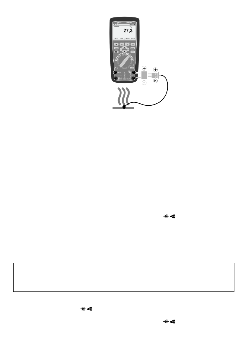
6.3 Temperature measurement
To perform the measurement:
set the rotary switch at mVTemp,
select MENU,
use arrows and F1 F2 F3 F4 buttons to set the temperature measurement Temp and unit –Cel-
sius Cor Fahrenheit F,
place the adapter of the temperature probe in COM terminal (black leg) and VΩCAP
Hz% Temp (red leg):
place the temperature probe in the adapter, as shown in the figure:
thin pin of the probe (marked as +) fits to terminal +;
thick pin of the probe (marked as K) fits to terminal –;
reversed connection of the probe is mechanically impossible,
contact the head of the temperature probe to the device under test. Maintain the contact of the
probe head with the part of the device under test, until the reading stabilizes.
read the measurement result on the display,
after completing the measurements, disconnect the probe from the meter.
10
CMM-60 –USER MANUAL
When you test temperature changes of the object relative to the base value, the meter may be ad-
justed to show these deviations. To do this, set the reference temperature:
use F1 F2 F3 F4 buttons to select OFFSET,
set the required temperature offset value:
use ◄► arrows to select segment for editing,
use ▲▼ arrows to set the desired value,
select OK.
6.4 Measurement of frequency or % of duty cycle (pulse filling indi-
cator)
To perform the measurement:
set the rotary switch at Hz%,
select MENU and use arrows and F1 F2 F3 F4 buttons to set one of three modes:
Hz frequency measurement
Hz,% frequency measurement and % of the duty cycle
connect black test lead to COM terminal and red test lead to VΩCAP Hz% Temp terminal,
contact the tips of test probes to the points of measurement; red probe should be applied to the
point of higher potential,
read the measurement result on the display,
after completing the measurements, remove test leads from the terminals of the meter.
6.5 Measurement of resistance
WARNING:
Do not perform measurements on the circuit under the voltage. Before the measurement dis-
connect the power and discharge capacitors.
To perform the resistance measurement:
set the rotary switch at ΩCAP,
select MENU and use arrows and F1 F2 F3 F4 buttons to set Ohms,
connect black test lead to COM terminal and red test lead to VΩCAP Hz% Temp terminal,
11

CMM-60 –USER MANUAL
contact the tips of test probes to the points of measurement; the best solution is to disconnect
one side of the tested element, to prevent the remaining part of the circuit interfere with the read-
out of the resistance value,
read the measurement result on the display,
after completing the measurements, remove test leads from the terminals of the meter.
6.6 Circuit continuity test
WARNING:
Do not perform measurements on the circuit under the voltage. Before the measurement dis-
connect the power and discharge capacitors.
To perform the continuity test:
set the rotary switch at ΩCAP,
connect black test lead to COM terminal and red test lead to VΩCAP Hz% Temp terminal,
select MENU and use arrows and F1 F2 F3 F4 buttons to set Beeper,
contact the tips of test probes to the points of measurement,
read the measurement result on the display; the beep will be activated when resistance values
are below approx. 25 Ω. If the circuit is open, the display will show OL,
after completing the measurements, remove test leads from the terminals of the meter.
6.7 Diode test
WARNING:
Do not perform measurements on the circuit under the voltage. Before the measurement dis-
connect the power and discharge capacitors. Do not test the diode under voltage.
To perform the diode test:
set the rotary switch at ΩCAP,
connect black test lead to COM terminal and red test lead to VΩCAP Hz% Temp terminal,
select MENU and use arrows and F1 F2 F3 F4 buttons to set Diode,
contact the pins of test probes to the diode: red test lead should contact the anode and the black
should contact cathode,
read the test result on the display - the forward voltage is displayed.
For a typical silicon rectifier diode, it is approx. 0.7 V, and for a germanium diode it is approx. 0.3
V
For LEDs with a low power, typical voltage value is in the range of 1.2…5.0 V depending on the
colour.
If the diode is polarized in the reverse direction, or there is a break in the circuit, the display will
show OL.
When the diode is shorted, the meter will show a value near 0 V.
after completing the measurements, remove test leads from the terminals of the meter.
12

CMM-60 –USER MANUAL
6.8 Measurement of capacitance
WARNING:
Risk of electric shock. Disconnect the power supply from the tested capacitor and discharge
all capacitors before any starting capacity measurements.
To perform the measurement:
set the rotary switch at ΩCAP,
connect black test lead to COM terminal and red test lead to VΩCAP Hz% Temp terminal,
select MENU and use arrows and F1 F2 F3 F4 buttons to set CAP,
contact the probe tips to the tested capacitor,
read the measurement result on the display,
after completing the measurements, remove test leads from the terminals of the meter.
6.9 Current measurement up to 10 A
NOTE
Do not make current measurements of 20 A DC and AC for longer than 30 seconds. Exceeding
this time may cause damage to the meter and/or test leads.
To perform the current measurement:
set the rotary switch at 10A ,
select MENU and use arrows and F1 F2 F3 F4 buttons to set the measurement of:
direct current voltage DC (default setting),
alternating current voltage AC,
connect black test lead to COM terminal and red test lead to 10A terminal,
remove power supply from the measured circuit and then connect the meter in series to the cir-
cuit at the point where the current is to be measured,
contact the probes to the poles of the tested object;
Direct Current (DC): the pin of black probe should contact negative pole of the circuit, while
the pin of red probe should contact positive pole of the circuit,
turn on the power supply of the circuit,
read the measurement result on the display,
after completing the measurements, remove test leads from the terminals of the meter.
6.10 Current measurement up to 500 mA
To perform the current measurement:
set the rotary switch at mA ,
select MENU and use arrows and F1 F2 F3 F4 buttons to set the measurement of:
direct current voltage DC (default setting),
alternating current voltage AC,
connect black test lead to COM terminal and red test lead to µA/mA terminal,
remove power supply from the measured circuit and then connect the meter in series to the cir-
cuit at the point where the current is to be measured,
13

CMM-60 –USER MANUAL
Direct Current (DC): the pin of black probe should contact negative pole of the circuit, while
the pin of red probe should contact positive pole,
turn on the power supply of the circuit,
read the measurement result on the display,
after completing the measurements, remove test leads from the terminals of the meter.
6.11 Current measurement up to 5000 µA
To perform the current measurement:
set the rotary switch at μA,
select MENU and use arrows and F1 F2 F3 F4 buttons to set the measurement of:
direct current voltage DC (default setting),
alternating current voltage AC,
connect black test lead to COM terminal and red test lead to µA/mA terminal,
remove power supply from the measured circuit and then connect the meter in series to the cir-
cuit at the point where the current is to be measured,
Direct Current (DC): the pin of black probe should contact negative pole of the circuit, while
the pin of red probe should contact positive pole,
turn on the power supply of the circuit,
read the measurement result on the display,
after completing the measurements, remove test leads from the terminals of the meter.
6.12 Measurement of current loop 4~20mA %
To perform the measurement:
set the rotary switch at 4~20mA%,
select MENU and use arrows and F1 F2 F3 F4 buttons to set 4-20 mA,
connect black test lead to COM terminal and red test lead to µA/mA terminal,
turn on the meter in series with the circuit under test;
the meter will display loop current as % value with:
0 mA = -25%,
4 mA = 0%,
20 mA = 100%,
24 mA = 125%.
14

CMM-60 –USER MANUAL
7 Special features
7.1 MENU panel
For each of the main measurement functions, described in sec. 6.1-6.12, there are sub-functions
available. They may be selected by pressing F1 button in MENU.
In addition to the functions described in section 6, the meter determines:
peak values of measured signals
Crest Factor
constant and periodic component of voltage and current
frequency and half-period
relative values of the measured values
Select the desired mode using arrows and F1 F2 F3 F4 buttons.
7.1.1 Displaying AC and DC components
The meter measures the AC and DC component of the measured signal (voltage or current).
Readings of these values may be displayed separately or together, as shown below.
From MENU the following modes are available:
AC+DC –reading is the sum of a periodic and constant component,
DC, AC –the main reading is constant component.
Note:
Measurement of peak values, frequency, duty cycle, relative values and frequency in this mode
is not available.
15
CMM-60 –USER MANUAL
7.1.2 Recording PEAK values
From MENU the following modes are available:
PEAK –displays the peak value of the measured, if it lasts more
than 1 ms.
CF (Crest Factor) –crest factor signal according to the following
formula:
sk
X
X
CF max
where:
Xmax –peak value
Xsk –RMS value
7.1.3 Relative measurement - REL
This mode enables a measurement relative to a stored reference value.
The displayed main result is the difference between the reference value (read-out at the moment of
activating REL mode) and the current read-out. Example: if the reference value is 20 A, and the cur-
rent reading is 12.5 A, then the main result on the display will be -7.5 A. If the new reading is identical
to the reference value, then the result will be zero.
From MENU select REL mode,
Current readings are presented as a deviation relative to the reference value
Use F3 to switch between reference units:
unit of the selected measurement function
%.
7.1.4 Mode: Hz,%,ms
This mode displays the frequency of the pulse filling indicator.
From MENU select mode: Hz,%,ms,
Use F1 F2 buttons to select:
Hz,% displays the frequency and pulse filling indicator in %
ms displays frequency and pulse width in ms
Note:
This mode is only active for current measurement
(except for 4~20mA% function) and voltage
7.2 HELP
Each measurement screen is provided with "Help" in English.
Press F3 to select HELP.
Use arrows or commands PREV/NEXT to scroll the help text to the desired location.
Help contains a description of:
functions MENU, SAVE, SETUP,
OL controls, batteries, sound,
RANGE, HOLD, MAX/MIN buttons, arrows,
CLOSE - closes the help.
When the help is active, the top bar of the display shows the current meter reading.
16
CMM-60 –USER MANUAL
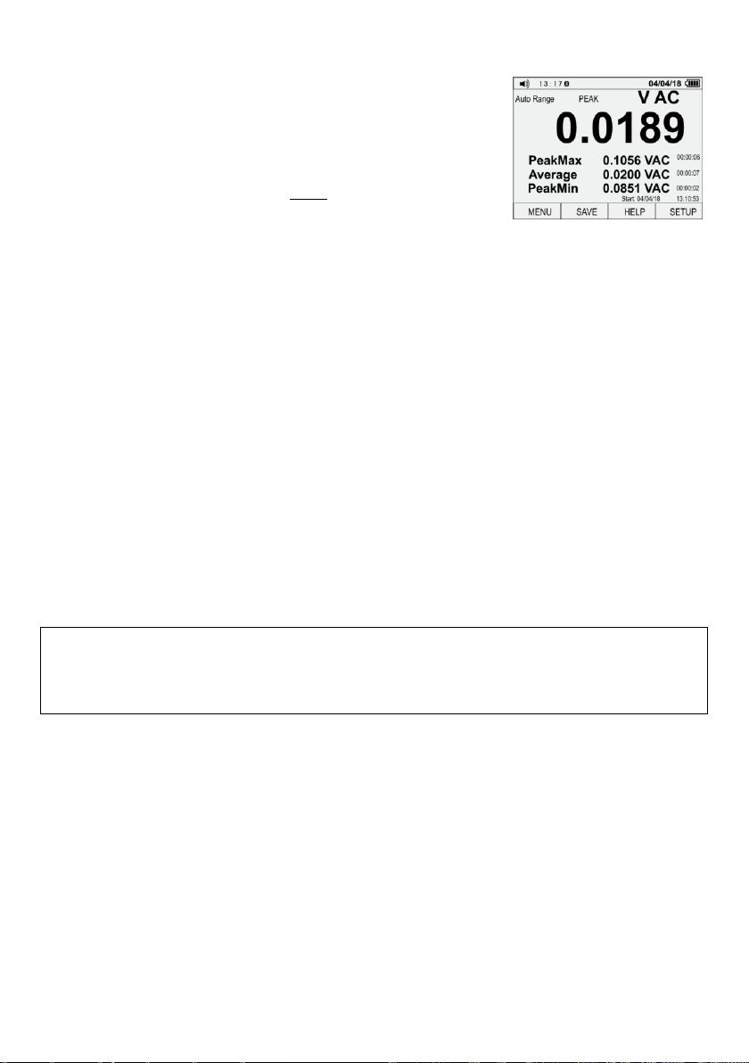
7.3 MAX/MIN mode
For each measurement function, this mode displays three values in the form of True RMS:
Minimum recorded value of the measurement,
Average of all recorded measurements,
Maximum recorded value of the measurement.
Prerequisite: the duration of the record must exceed 100 ms.
If the measured signal drops below the current minimum value or exceeds maximum value, the
readings will be updated to the value of this signal. The meter records also date, time and the period
after which it recorded these values.
Using the function:
Use the rotary switch to select the desired measuring function
Press MAX/MIN button
use F1 F2 F3 F4 buttons to select one of the options:
Restart - resetting the readings and restarting the recording,
STOP - stopping the recording and presentation of the most recent readings,
SAVE - saving records to the meter's memory. Active after selecting STOP. Detailed de-
scription in section 7.6.2.
CLOSE - closing the function without saving results.
Note:
When the meter switches off automatically and then it is restarted with ESC button, data on the
screen will be lost.
7.4 HOLD function
This function is used to 'freeze' the measurement result on the display.
Using the function:
to activate, press HOLD button,
to save the result use F1 F2 F3 F4 buttons to select SAVE,
to turn off, press HOLD button or select CLOSE.
The activity of the function is signalled by message HOLD. Then, the upper bar of the display
shows the current measured signal.
An additional mode of the function is AutoHold. It monitors the input signal and updates the "fro-
zen" read-out, when the meter detects a new stable value of the signal (such that variations for at
least 1 s. do not exceed the setpoint –sec. 7.7.3).
In addition, the meter detects open measurement circuit. This allows user to plug the meter into a
different circuit, without losing the current reading from the screen.
Using the function:
to activate, use F1 F2 F3 F4 buttons and select AUTOHOLD,
to save the result use F1 F2 F3 F4 buttons to select SAVE,
to turn off, select CLOSE or CANCEL.
17
CMM-60 –USER MANUAL
Note:
AutoHold is disabled, if the meter is in Peak, MIN/MAX mode or when it records the wave-
forms.
Note:
When the meter switches off automatically and then it is restarted with ESC button, data on the
screen will be lost.
7.5 Changing measurement RANGE
Some measurements require manual selection of the measurement range. For this purpose:
shortly press RANGE, to enable manual range change
shortly press RANGE, to change the range. Available ranges, depending on the measured value,
are shown in sec. 14.1,
press and hold RANGE for approx. 2 s, to return to automatic mode.
Note:
Manual range selection is not used for the function of measuring the current of 4~20 mA, 10 A,
temperature, frequency, duty cycle, continuity, diode tests and for sub-functions: REL, PEAK
and CF.
7.6 Memory of the meter
7.6.1 Recording the waveforms
For any measurement function, the variation of measured value in time may be recorded. For this pur-
pose:
use F1 F2 F3 F4 buttons to select SAVE,
use arrows to select RECORD and confirm by F1 button,
use arrows and F1 F2 F3 F4 buttons to set recording parameters:
Set Duration in DD-HH-MM format
Sample Interval in MM-SS format
Note:
These variables affect the recording length and the number of saved samples. Both variables
may interact with each other; changing one may automatically change the other, in order to fit
the data in the available memory of the meter.
use START command to start recording,
recording ends after pressing STOP or when the measurement time (duration) is reached.
Functions of buttons:
EDIT - editing parameter
arrows ◄► selecting values to be edited
arrows ▲▼ changing values
OK confirming changes
START starting the recording process
STOP stopping the recording process
18
Other manuals for CMM-60
1
Table of contents
Other Sonel Multimeter manuals


